Wistron NeWeb CB1GA21VM Integrate with certified module-End product User Manual 1
Wistron NeWeb Corporation Integrate with certified module-End product 1
UserManual.wiki
>
Wistron NeWeb
>
CB1GA21VM User Manual
User Manual_1
Navigation menu
Upload a User Manual
Namespaces
Wiki Guide
HTML
PDF
Info
Views
User Manual
Discussion / Help
Navigation
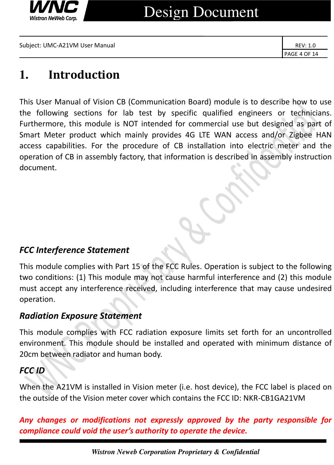
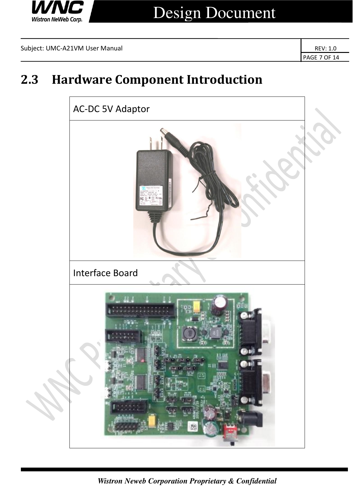
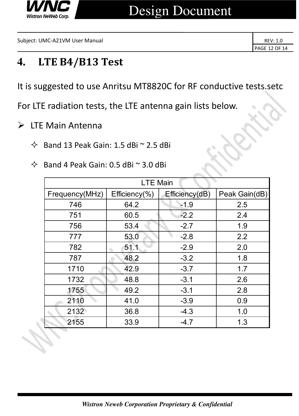
![Subject: UMC-A21VM User Manual REV: 1.0 PAGE 5 OF 14 Wistron Neweb Corporation Proprietary & Confidential Design Document 2. Test Setup Configuration 2.1 Power Supply and Debug Console Connection Power on Sequence: I. Connect 12-pin-to-Jig-baord cable II. Attach AC-DC Adaptor & USB Debug Port Cable III. Wait for 20 seconds when system ready (See Note 1) IV. Plug-in Console Port cable [Caution] Improper power on sequence might lead to system boot-up failure! USB Debug Port Console Interface Board AC-DC 5V Adaptor DUT (CB)](https://usermanual.wiki/Wistron-NeWeb/CB1GA21VM/User-Guide-3700805-Page-5.png)