Wistron NeWeb CB500AG 802.11a/b/g WLAN Cardbus Adapter User Manual FCC
Wistron NeWeb Corporation 802.11a/b/g WLAN Cardbus Adapter FCC
UserManual.wiki
>
Wistron NeWeb
>
CB500AG User Manual
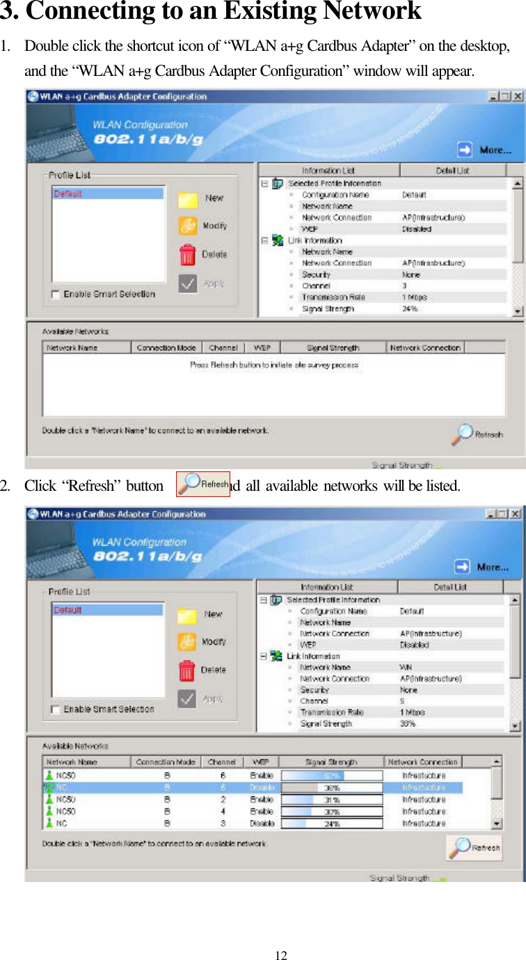
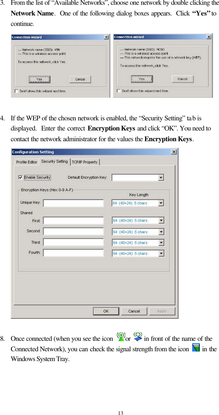
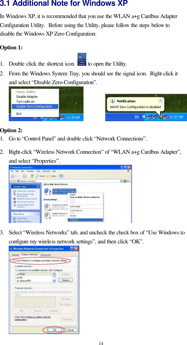
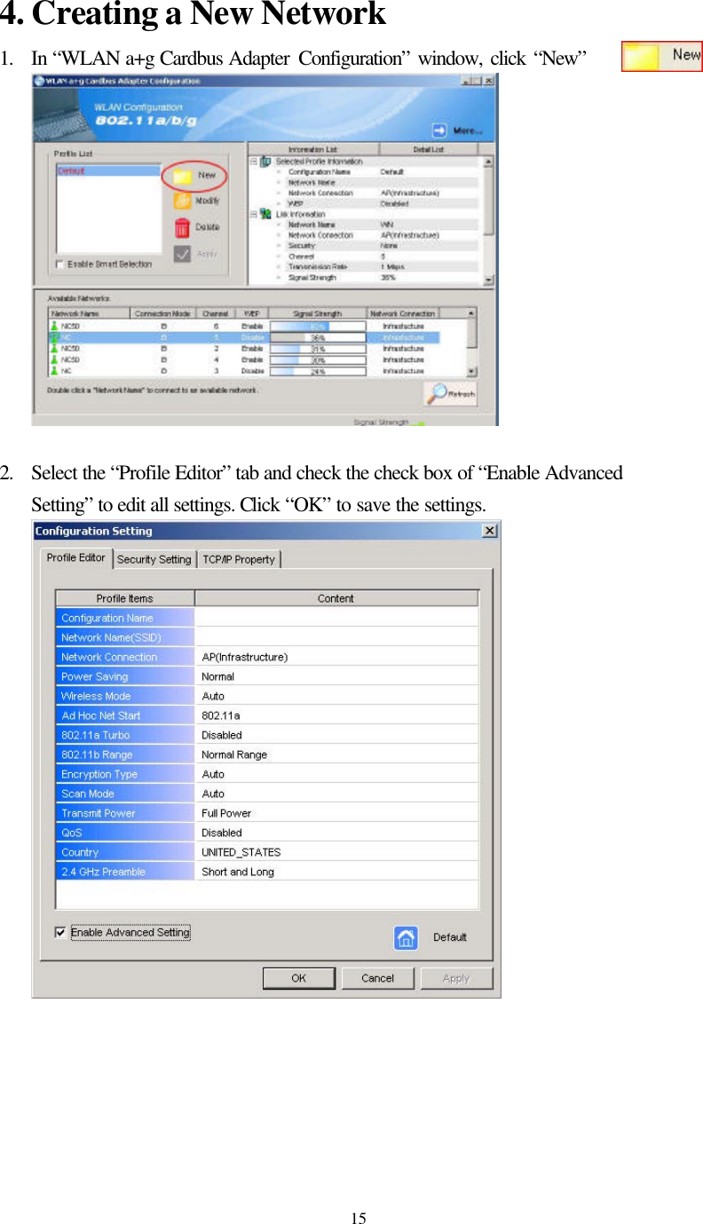
Users Manual
Navigation menu
Upload a User Manual
Namespaces
Wiki Guide
HTML
PDF
Info
Views
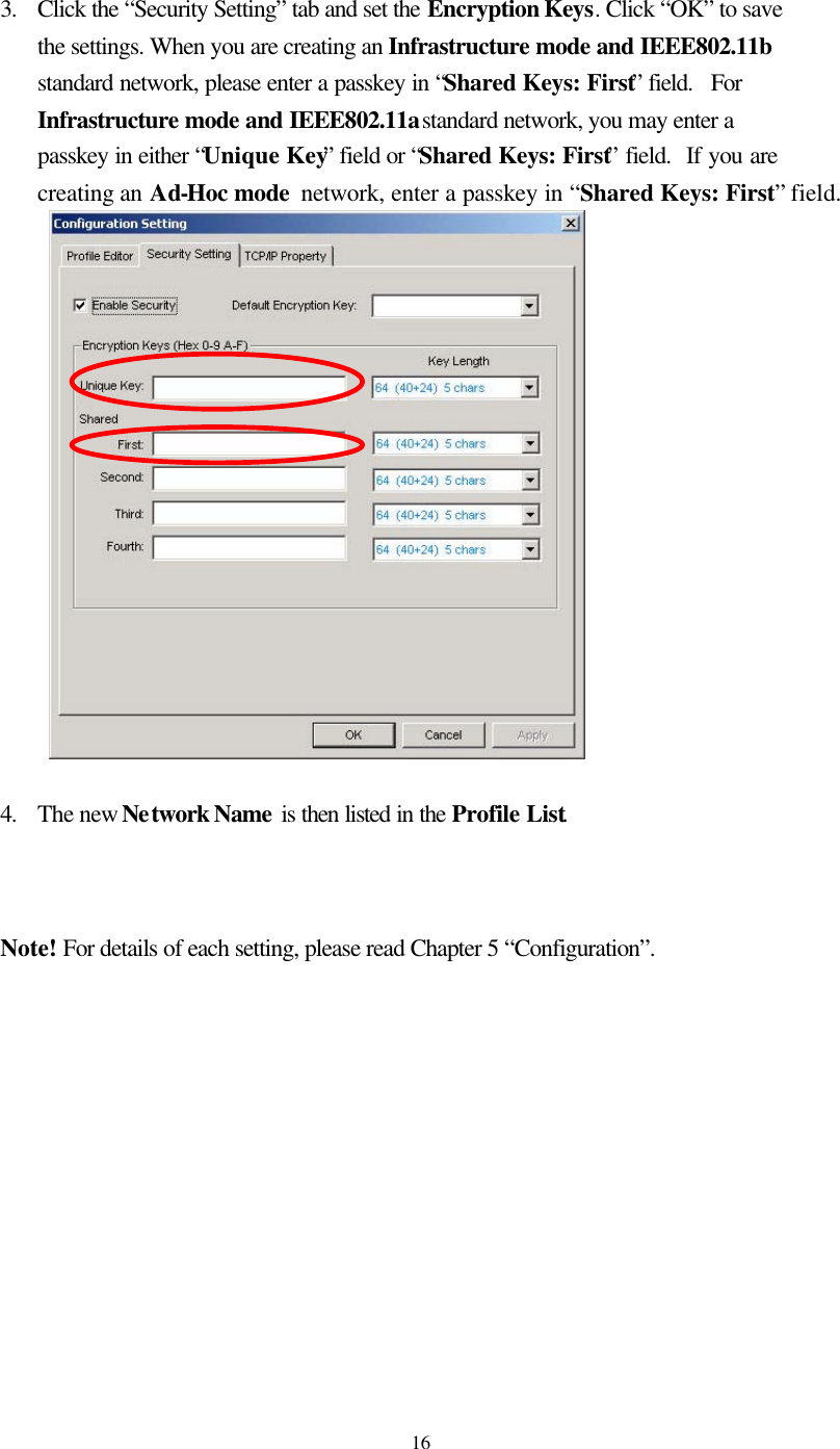
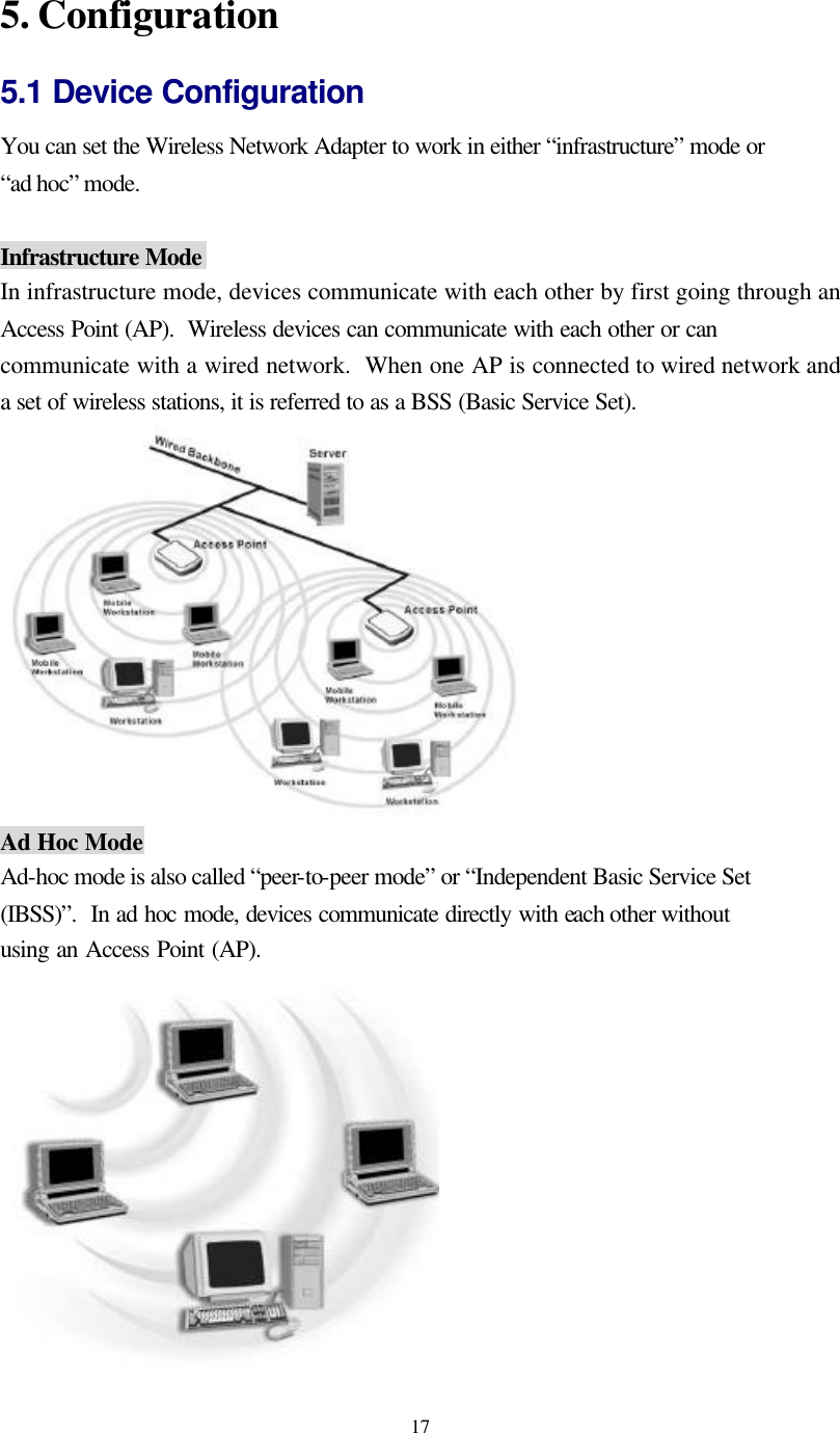
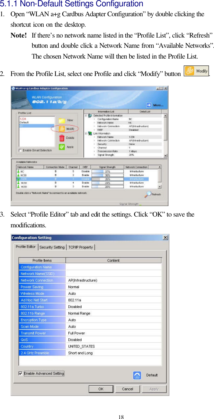
User Manual
Discussion / Help
Navigation