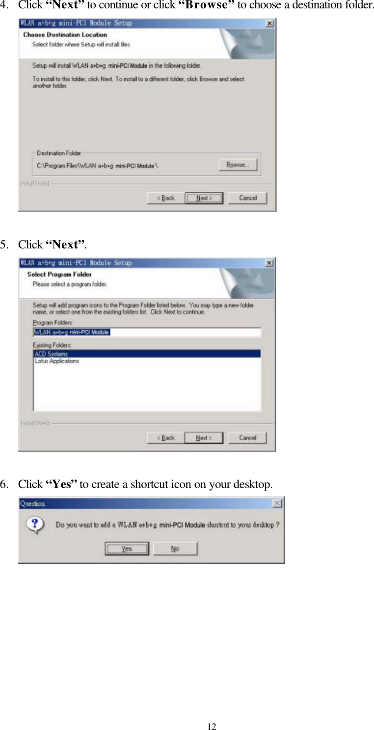
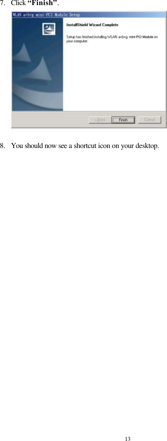
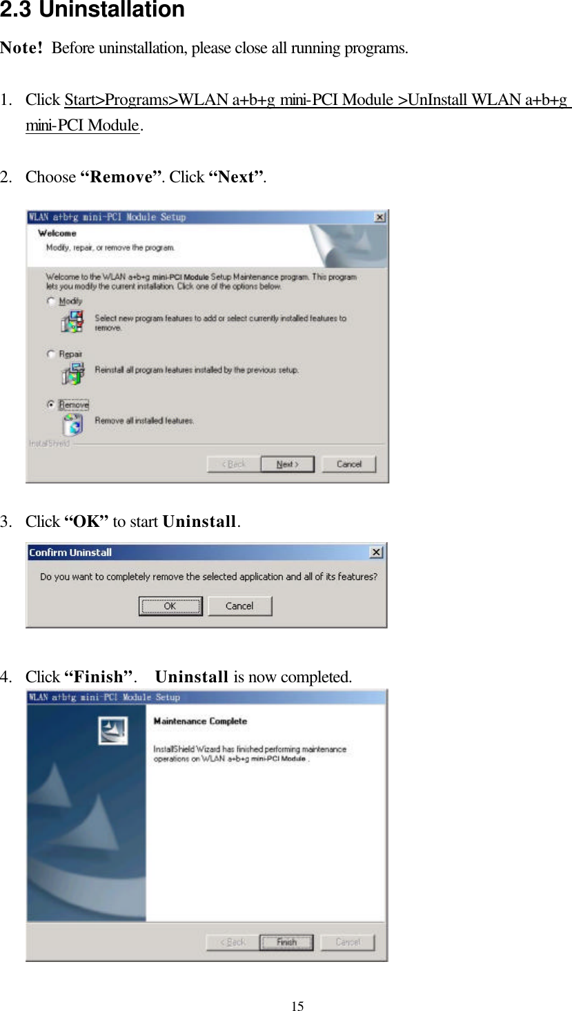
Wistron NeWeb CM9 WLAN a+b+g mini-PCI Module User Manual CM9 G Manual 0604
Wistron NeWeb Corporation WLAN a+b+g mini-PCI Module CM9 G Manual 0604
UserManual.wiki
>
Wistron NeWeb
>
CM9 User Manual
>
Manual revised
Contents
1.
Manual revised
2.
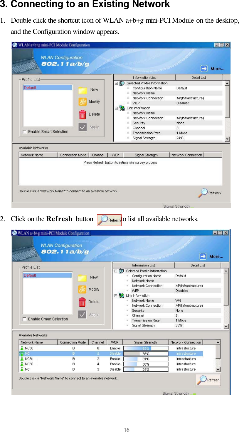
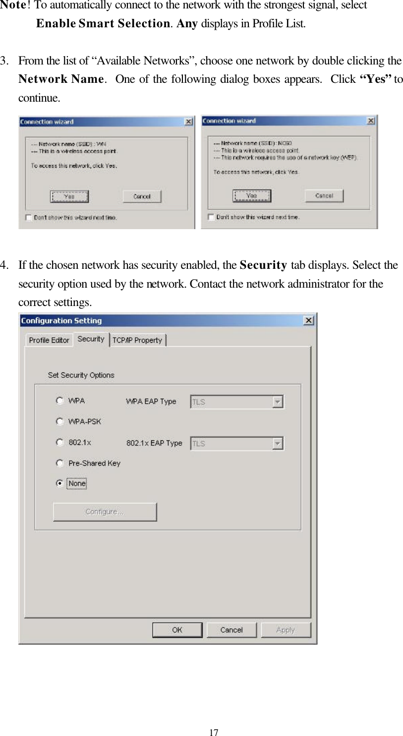
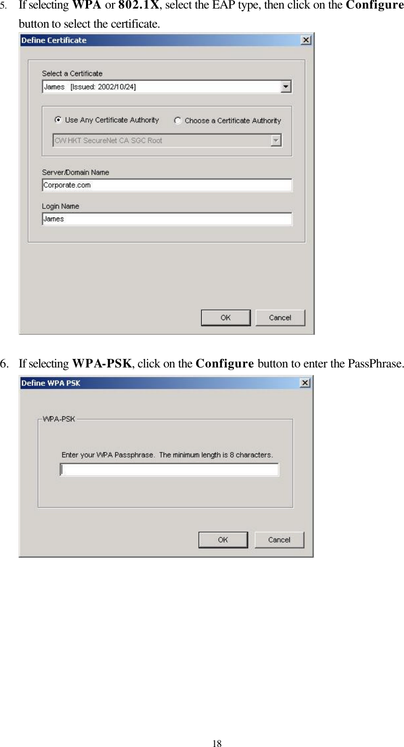
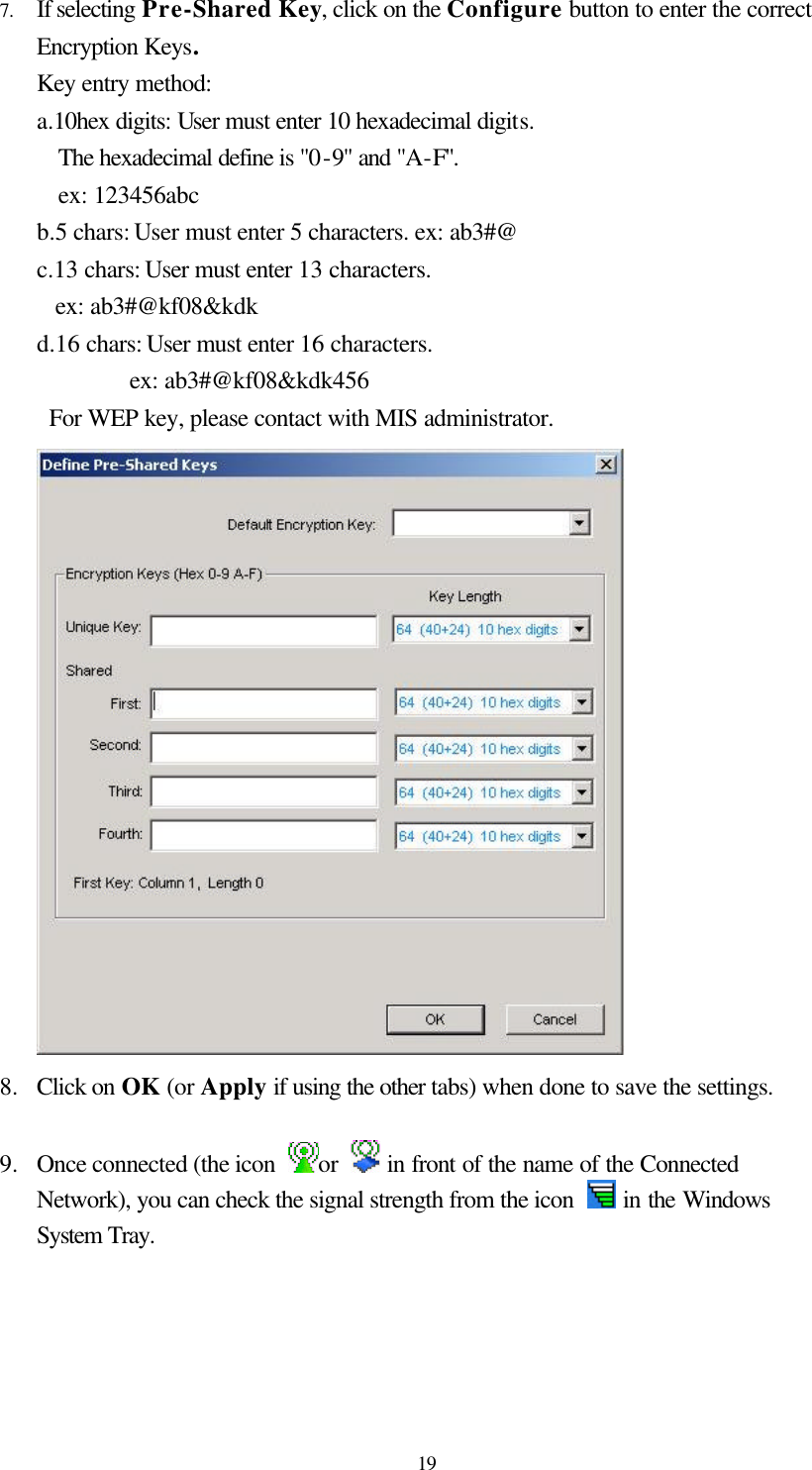
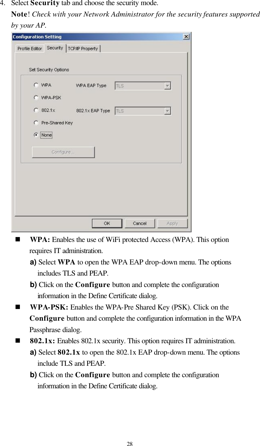
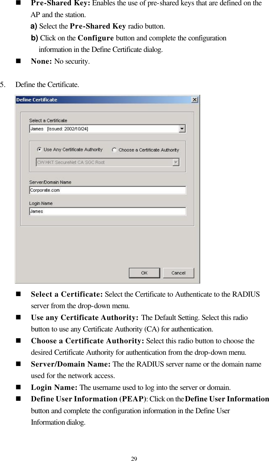
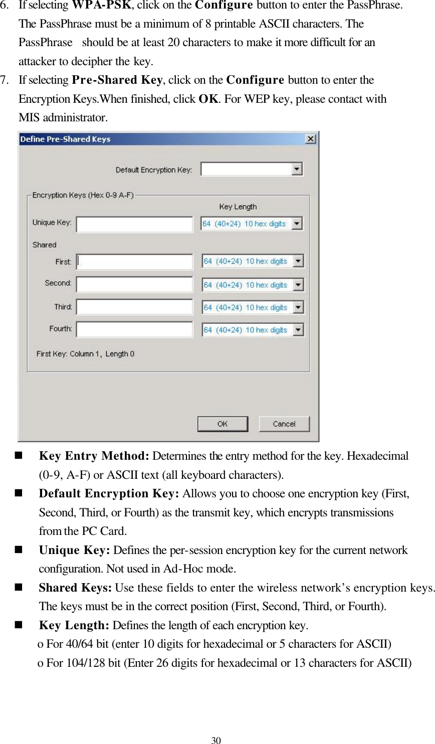
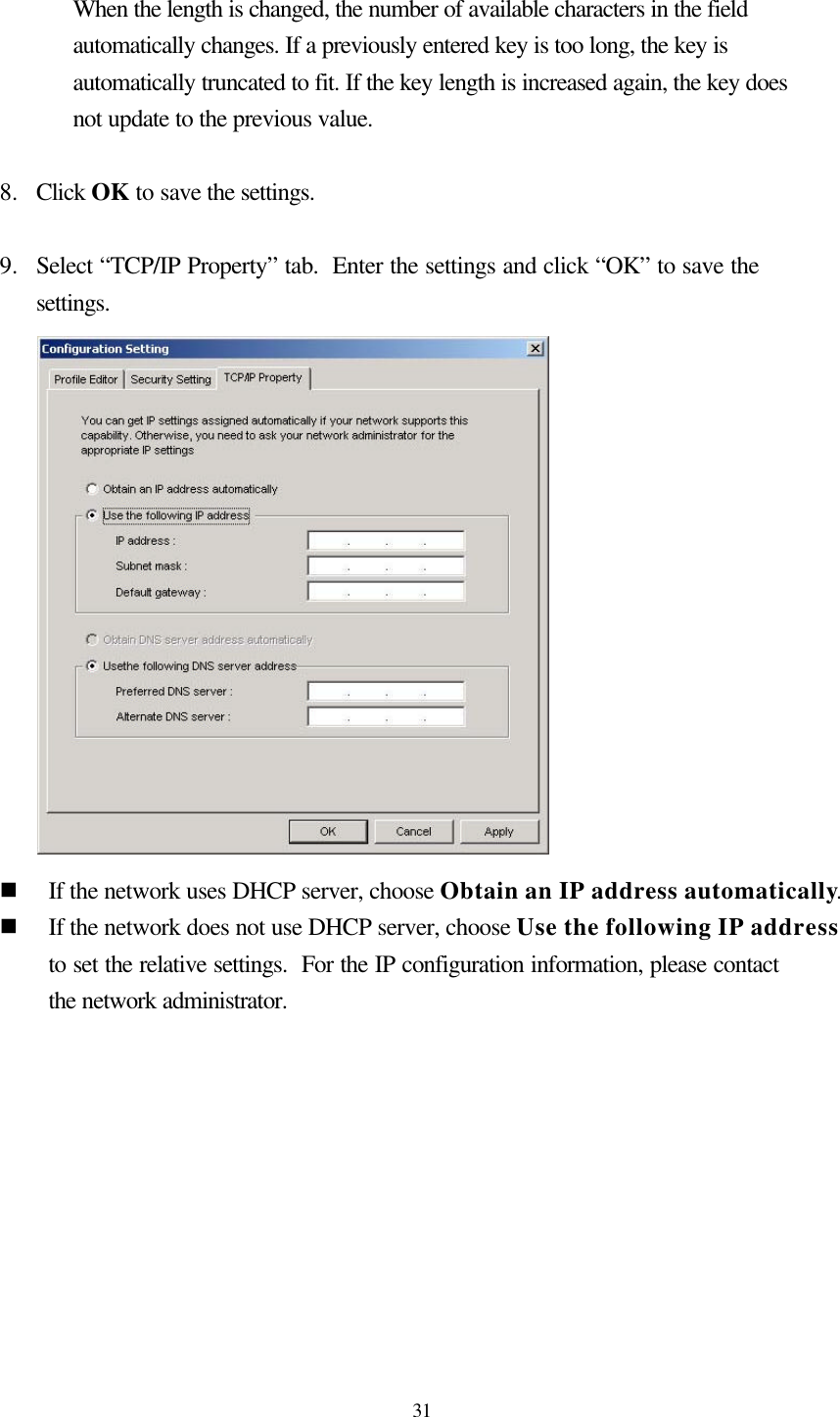
Manual
Manual revised
Navigation menu
Upload a User Manual
Namespaces
Wiki Guide
HTML
PDF
Info
Views
User Manual
Discussion / Help
Navigation