Wistron NeWeb D52A1 Connected Cooler Radio Rest of World version User Manual
Wistron NeWeb Corporation Connected Cooler Radio Rest of World version
User manual
Quick Start Guide
Connected Cooler Radio

Table of Contents
1. GETTING STARTED ............................................................................................... 5
1.1 UNPACKING INFORMATION ...................................................................................... 5
1.2 INTRODUCTION ...................................................................................................... 5
2. PORTS AND LED INDICATORS .............................................................................. 6
2.1 PORTS ................................................................................................................. 6
2.2 LED INDICATORS .................................................................................................... 7
3. INSTALLATION ..................................................................................................... 8
4. SPECIFICATIONS ................................................................................................ 10

Declaration of Conformity
Manufacturer:
Name: Wistron NeWeb Corporation
Address: 20 Park Avenue II, Hsinchu Science Park, Hsinchu 308, Taiwan,
R.O.C
Radio Equipment:
Model: D52A1
Description: Connected Cooler Radio Rest of World version
Marketing Name: D52A1
Radio-related Software Version: D52A1_v00.00
Supplied Accessories and Components: NA
We, Wistron NeWeb Corporation, declare under our sole responsibility that the
product described above is in conformity with the relevant Union harmonization
legislation:
RE Directive (2014/53/EU), RoHS Directive (2011/65/EU)
The following harmonized standards and/or other relevant standards have been
applied:
1. Health and Safety (Article 3.1(a) of the RE Directive)
EN 62311:2008
EN 60950-1:2006/A11:2009+A1:2010+A12:2011+A2:2013
2. Electromagnetic compatibility (Article 3.1 (b) of the RE Directive)
Final Draft ETSI EN 301 489-1 V2.1.1,
Draft ETSI EN 301 489-3 V2.1.0
Final Draft ETSI EN 301 489-17 V3.1.1
Draft ETSI EN 301 489-52 V1.1.0
3. Radio frequency spectrum usage (Article 3.2 of the RE Directive)
ETSI EN 301 908-1 V11.1.1, ETSI EN 301 908-2 V11.1.1
ETSI EN 300 328 V2.1.1
Draft ETSI EN 301 511 V12.1.10
Draft ETSI EN 300 440 V2.1.0
4. RoHS Directive (2011/65/EU)
EN 50581:2012

Signed for and on behalf of: Wistron NeWeb Corporation
Place: 20 Park Avenue II, Hsinchu Science Park, Hsinchu 308, Taiwan, R.O.C; date:
January 4, 2017
Name: Brian Lin; function: Technical Manager; signature:
1. Getting Started
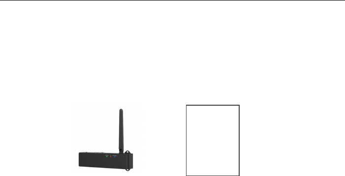
1.1 Unpacking Information
The Connected Cooler Radio (CCR)
Battery notice card
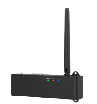
1.2 Introduction
The Connected Cooler Radio (CCR) works with sensors installed in coolers to
deliver cooler information to Cloud servers for better monitoring and
management. The Wi-Fi, AGPS, and 2G/3G (based on the models you select)
functions of the CCR enables stable delivery of accurate information collected
by analog or digital sensors.
Battery
Notice
Card
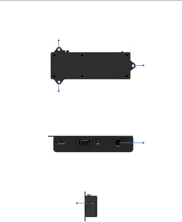
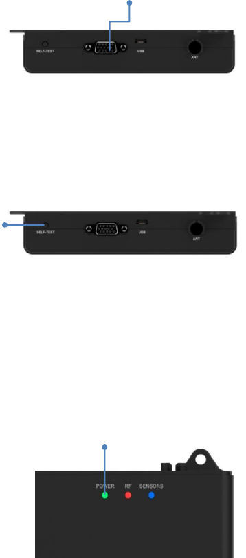
2. Ports and LED Indicators
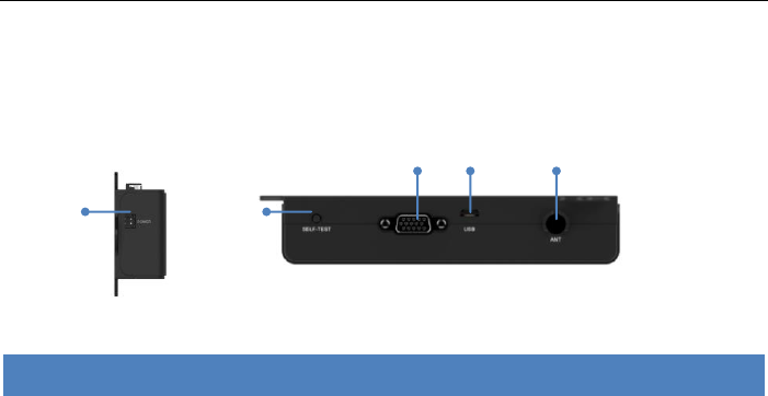
2.1 Ports
Port
Description
1
Power
Power supply connection
2
Self-test button
The button for activating the self-test process
3
Sensor port
Connects to sensors installed in the cooler
4
Engineering
For engineering uses only
5
ANT
Antenna connection
1
2
3
4
5
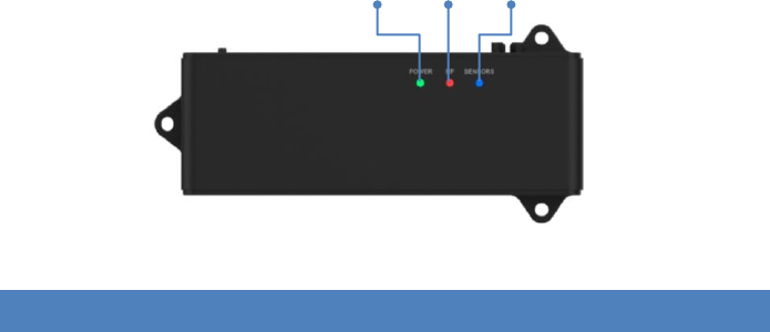
2.2 LED Indicators
LED
Indication
Description
Power
Steady green
All self-tests passed, and the battery is full.
Blinking green
All self-tests passed, and the battery is
charging
Off
No power connection
RF
Steady red
Other failures; for example, SIM card,
battery, or Wi-Fi functions
Blinking red
Unsuccessful antenna connection
Sensors
Steady blue
The self-test mode is running.
Blinking blue
Detected function failure of the
temperature sensor or door-open sensor.
Notes:
1) This table is only valid for checking the information after pressing the
self-test button.
2) The Power LED (Green) will be on during Operating AC mode.
Power
RF
Sensors
3. Installation
1. Place the CCR in the specified location (for example wall) and affix the
screws.
Screw use type M4
2. Attach the antenna to the antenna port of the CCR.
3. Connect the power port to the power supply.
Screw
Screw
Screw
Power
connection
Antenna
4. Connect the Sensor port to the sensors.
5. Press the Self-test button. The system begins testing the CCR and the
sensors attached to the CCR.
6. The system will be ready for use when the Power LED returns to steady
green, indicating the system functions normally.
Refer to the “LED Indicators” section of this document for details if other
LED indications are displayed.
Self-test
button
Sensors
Power LED
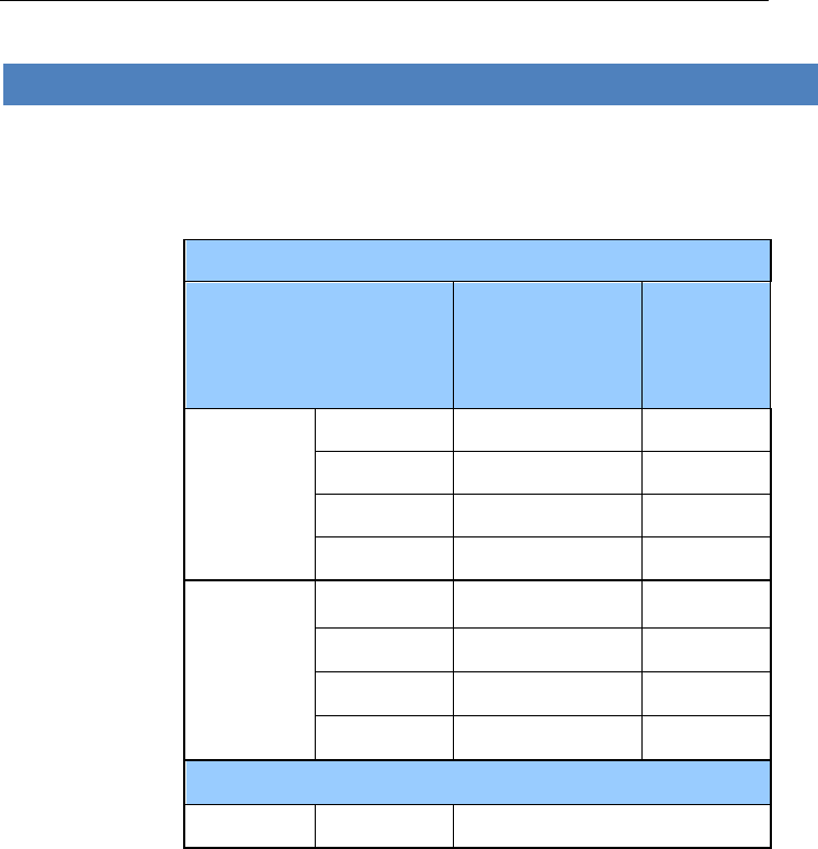
4. Specifications
Specifications
Standards
Wi-Fi: IEEE 802.11b/g/n (2.4 GHz)
BLE
3G: B1/2/5/8; GPRS/EDGE Quad-Band
Max. power
for each
frequency
And
Antenna Typy
Antenna Gain
Mobile
Max. Power (dBm)
Antenna
peak Gain
(dBi)
GPRS
Band(s)
GSM 850
34
1
E-GSM 900
34
0
DCS 1800
32
4
PCS 1900
30.8
4
UMTS
Band(s)
FDD I
25
4
FDD II
25
4
FDD V
25
1
FDD VIII
25
0
*Antenna Type
*Antenna
2G/3G
Fixed External Antenna
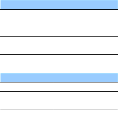
WLAN
WiFi TX
11b/g/n
Max Power(dBm)
17.9
Antenna peak Gain
(dBi)
1
Antenna type
internal PCB antenna
BLE
Max Power(dBm)
4
Antenna peak Gain
(dBi)
1
Antenna type
internal PCB antenna
Regions and
countries
applicable
Worldwide, out of USA and Canada.
Connection
interfaces
USIM 3FF, VGA for sensor(optional)
Power input
12 V DC/ 1A (powered by UL Listed power source.)
Backup battery: 3.7 V > 900 mAH Li-Ion
Environment
Ambient operating temperature: –20 °C to +60 °C
Storage temperature: –40 °C to +70 °C
Dimensions
150 mm (L) × 50 mm (W) ×30 mm (H)
(without antenna and screws)

5. Instruction
Instruction
CAUTION
Only authorized service providers shall replace battery.
Do not disassemble or open crush, bend or deform, puncture or shred
Do not modify or remanufacture, attempt to insert foreign objects into
the battery, immerse or expose to water or other liquids, expose to fire,
explosion or other hazard.
Only use the battery with a charging system that has been qualified with
the system per CTIA Certification Requirements for Battery System
Compliance to IEEE 1725. Use of an unqualified battery or charger may
present a risk of fire, explosion, leakage, or other hazard.
Replace the battery only with another battery that has been qualified
with the system per this standard, IEEE-Std-1725. Use of an unqualified
battery may present a risk of fire, explosion, leakage or other hazard.
Promptly dispose of used batteries in accordance with local regulations
Avoid dropping the device or battery. If the device or battery is dropped,
especially on a hard surface, and the user suspects damage, take it to a
service center for inspection.
Improper battery use may result in a fire, explosion or other hazard.
For those host devices that utilize a USB port as a charging source, the
host device's user manual shall include a statement that the device shall
only be connected to CTIA certified adapters, products that bear the
USB-IF logo or products that have
Specific Absorption Rate information
This mobile device meets the government’s requirements for
exposure to radio waves. Your mobile device is a radio
transmitter and receiver. The exposure standard for mobile
devices employs a unit of measurement known as the
Specific Absorption Rate, or SAR. The SAR limit adopted by
Europe is 2.0 W/kg averaged over 10 grams of tissue. Tests
for SAR are conducted using standard operating positions
with the device transmitting at its highest certified power
level in all tested frequency bands. The minimum distance
between the user and/or any bystander and the radiating
structure of the transmitter is 20cm.
FCC Regulations:
This device complies with part 15 of the FCC Rules.
Operation is subject to the following two conditions: (1)
This device may not cause harmful interference, and (2)
this device must accept any interference received,
including interference that may cause undesired
operation.
This device has been tested and found to comply with
the limits for a Class B digital device, pursuant to Part 15
of the FCC Rules. These limits are designed to provide
reasonable protection against harmful interference in a
residential installation. This equipment generates, uses
and can radiated radio frequency energy and, if not
installed and used in accordance with the instructions,
may cause harmful interference to radio
communications. However, there is no guarantee that
interference will not occur in a particular installation If
this equipment does cause harmful interference to radio
or television reception, which can be determined by
turning the equipment off and on, the user is
encouraged to try to correct the interference by one or
more of the following measures:
-Reorient or relocate the receiving antenna.
-Increase the separation between the equipment and
receiver.
-Connect the equipment into an outlet on a circuit
different from that to which the receiver is connected.
-Consult the dealer or an experienced radio/TV
technician for help.
Caution: Changes or modifications not expressly
approved by the party responsible for compliance could
void the user‘s authority to operate the equipment.
RF Exposure Information
This device complies with FCC radiation exposure limits
set forth for an uncontrolled environment. In order to
avoid the possibility of exceeding the FCC radio
frequency exposure limits, human proximity to the
antenna shall not be less than 20cm (8 inches) during
normal operation.