Wistron NeWeb DCMA81 WLAN 802.11 a/b/g MINI PCI MODULE User Manual
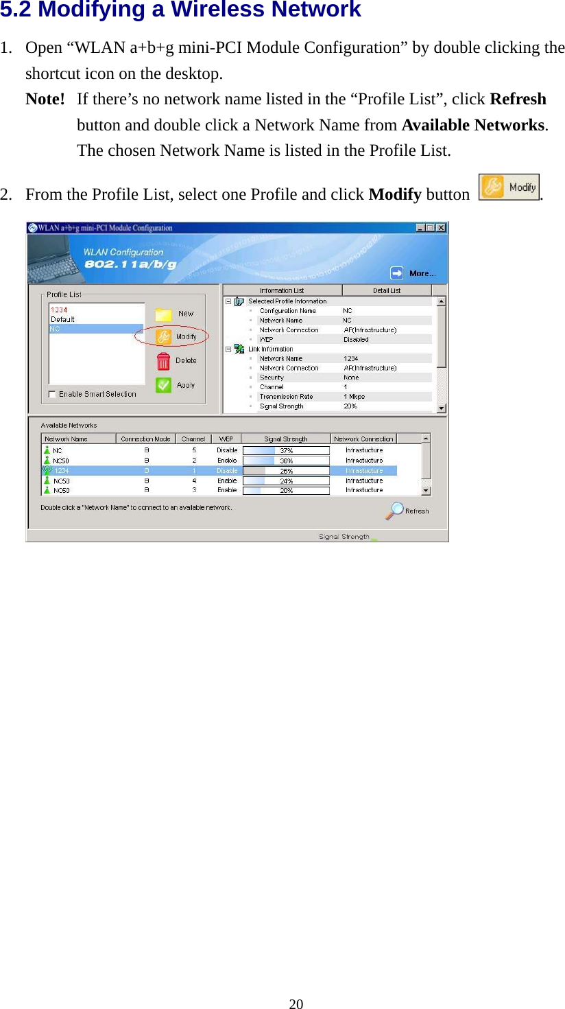
Wistron NeWeb Corporation WLAN 802.11 a/b/g MINI PCI MODULE
UserManual.wiki
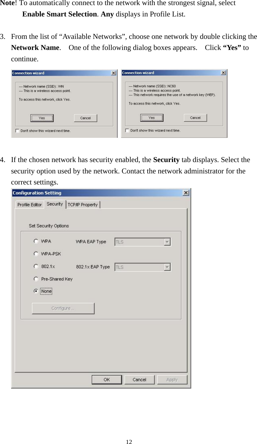
>
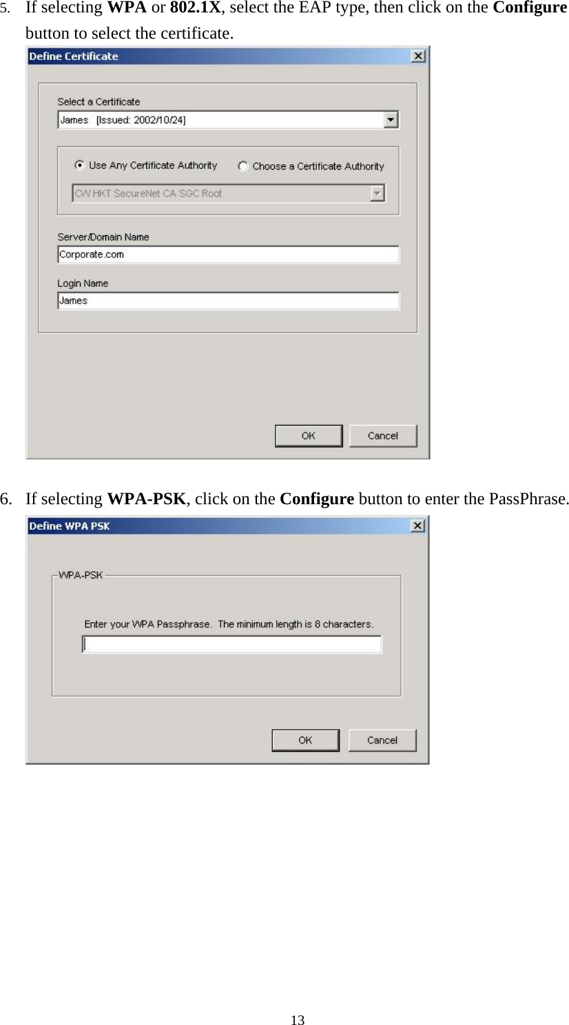
Wistron NeWeb
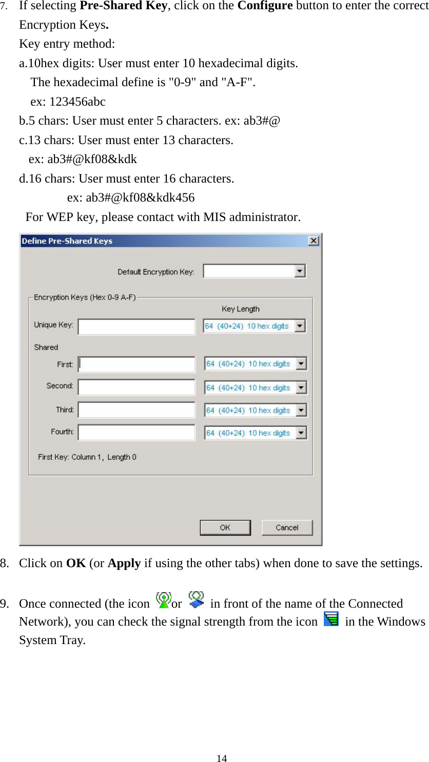
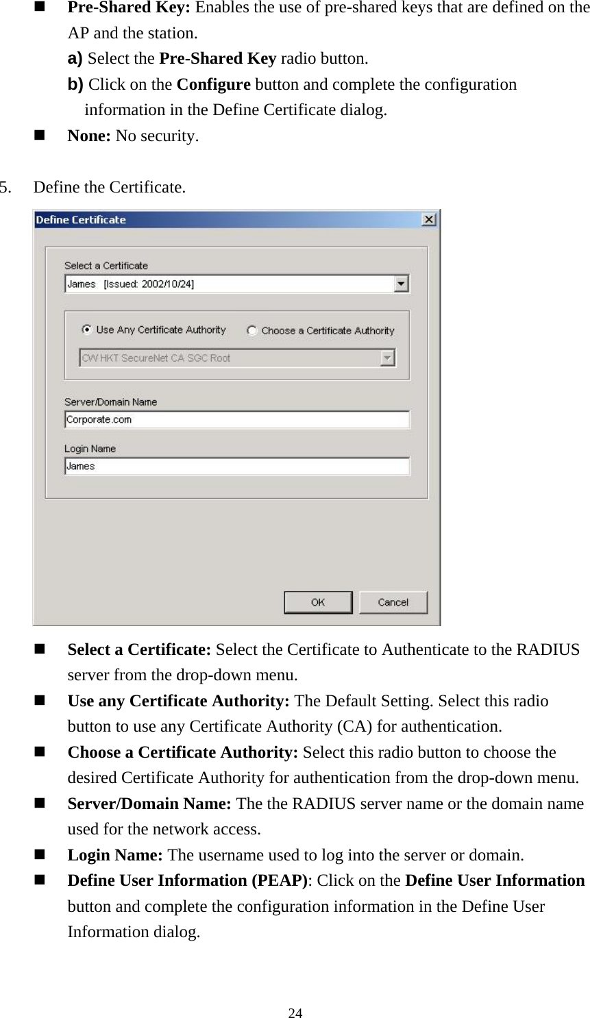
>
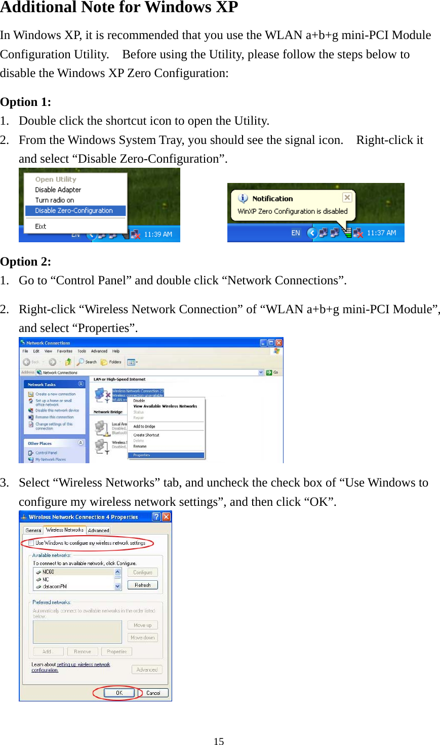
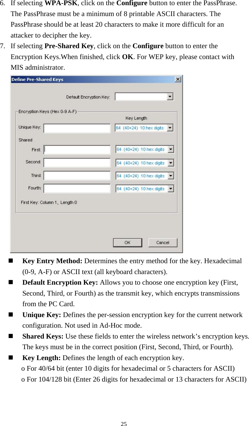
DCMA81 User Manual
>
ueser manual
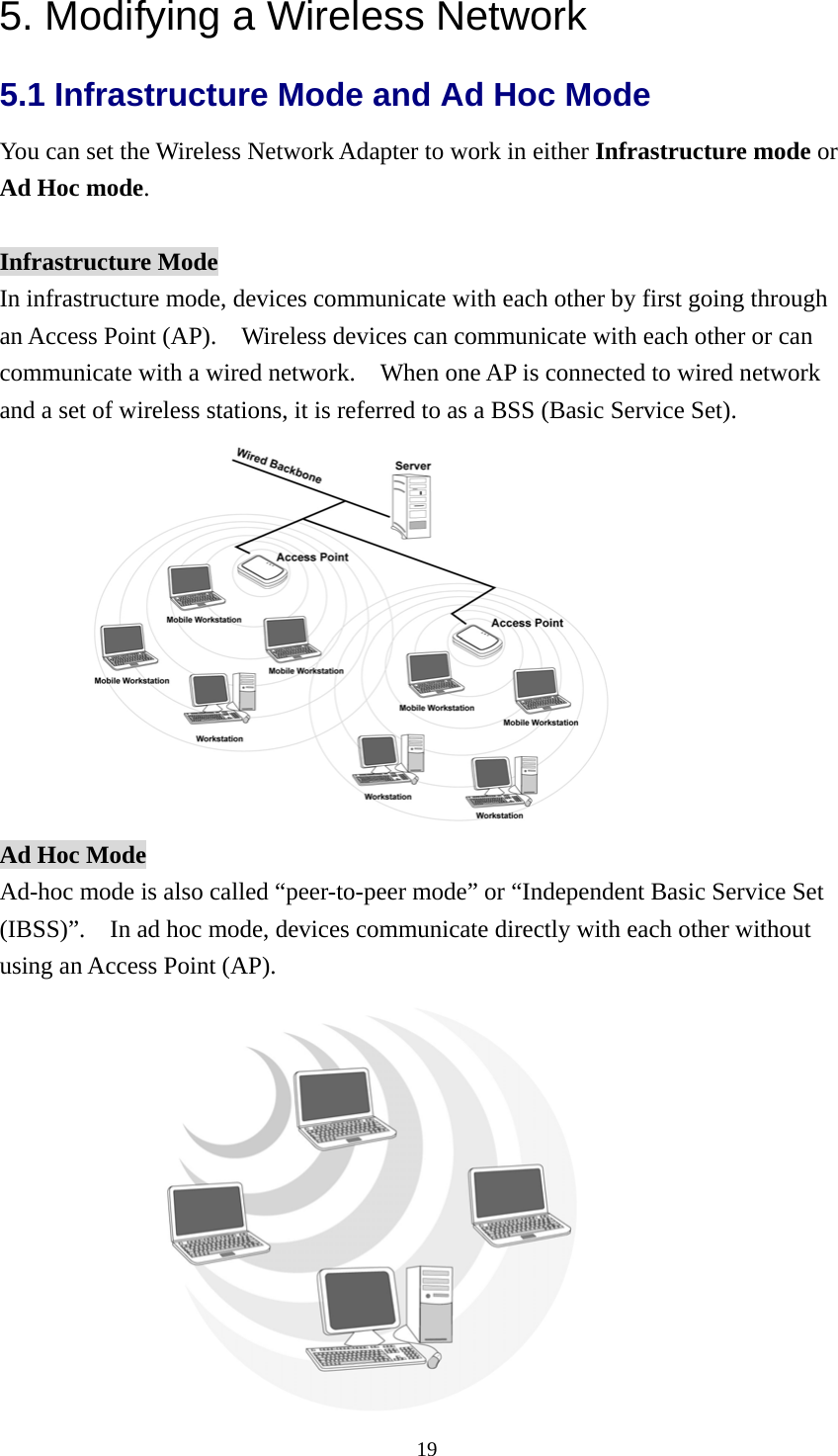
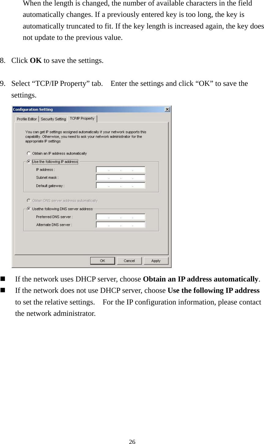
Contents
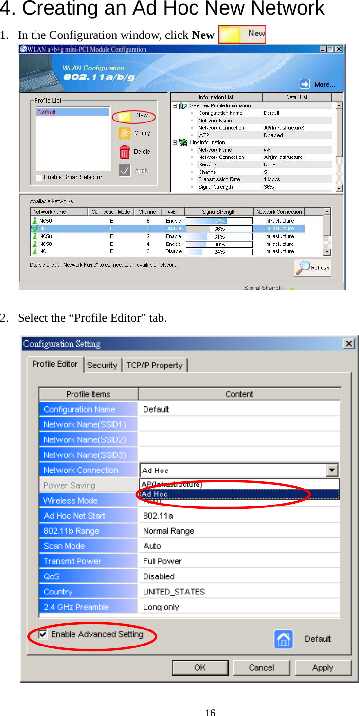
1.
ueser manual
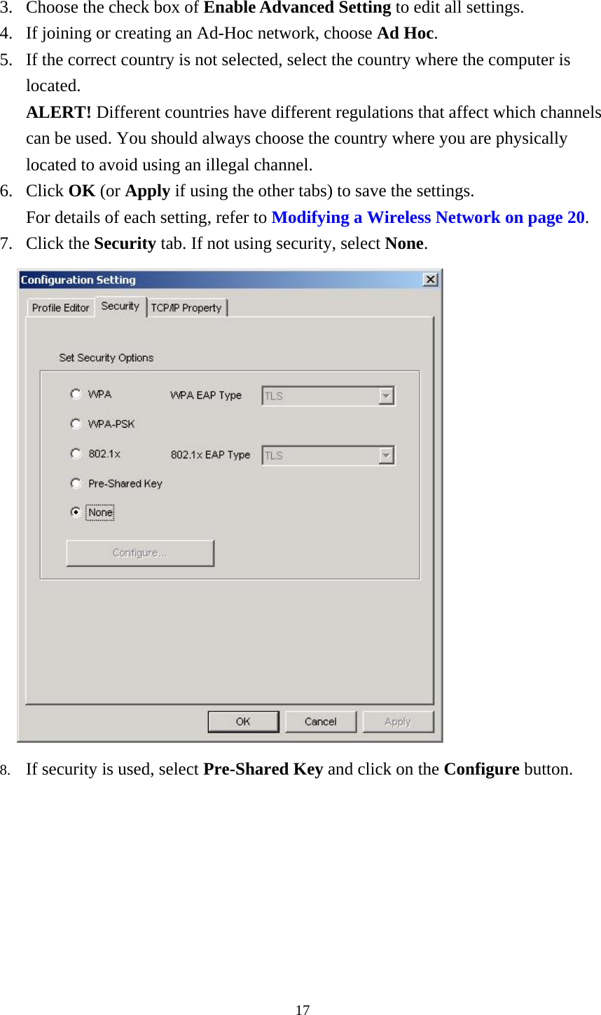
2.
User Manual
ueser manual
Navigation menu
Upload a User Manual
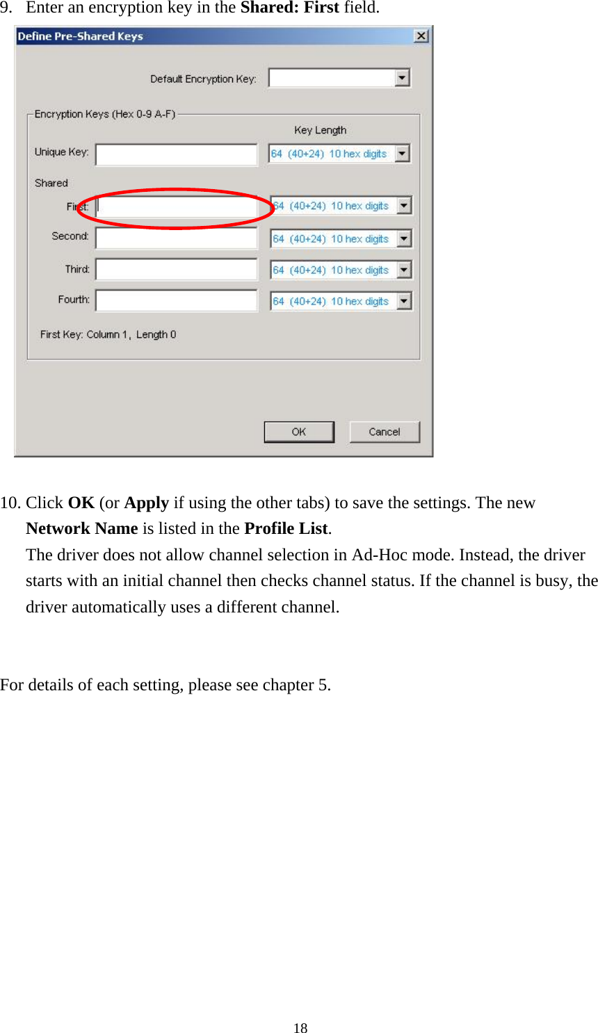
Namespaces
Wiki Guide
HTML
PDF
Info
Views
User Manual
Discussion / Help
Navigation