Wistron NeWeb DCMA82 High Powered 802.11a/g WLAN Mini-PCI 3A User Manual rev3
Wistron NeWeb Corporation High Powered 802.11a/g WLAN Mini-PCI 3A rev3
UserManual.wiki
>
Wistron NeWeb
>
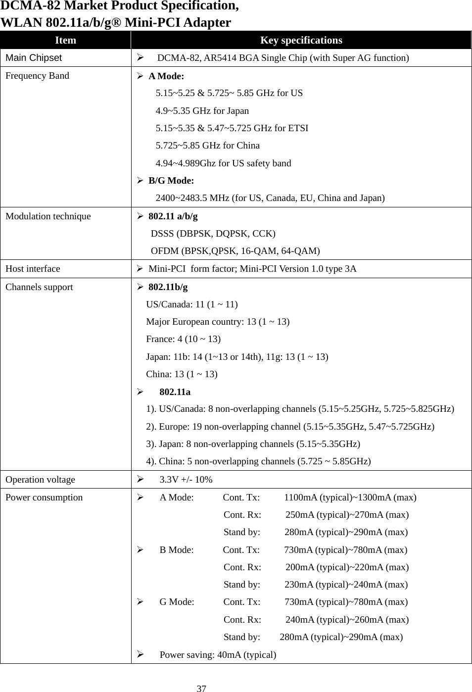
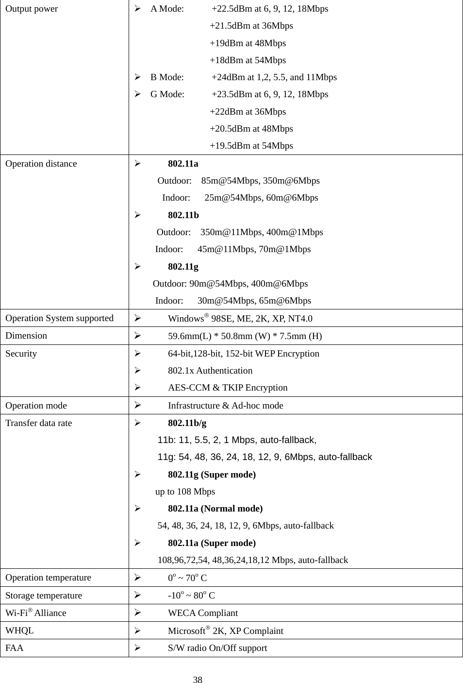
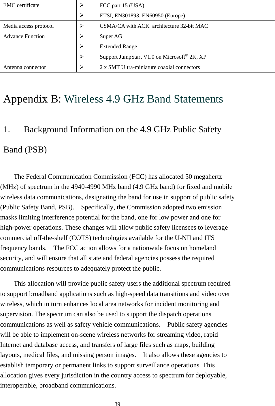
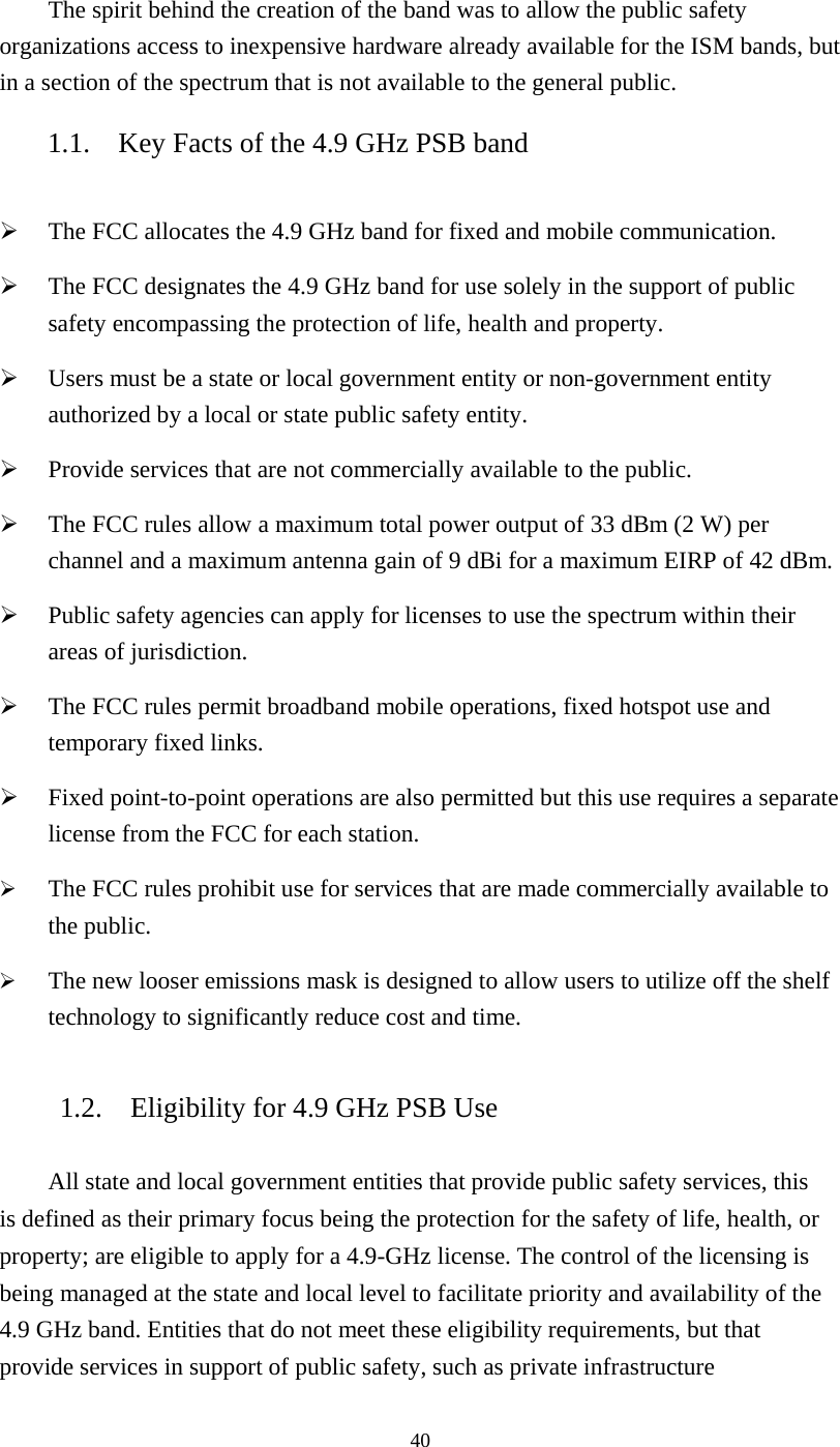
DCMA82 User Manual
User manual rev3
Navigation menu
Upload a User Manual
Namespaces
Wiki Guide
HTML
PDF
Info
Views
User Manual
Discussion / Help
Navigation