Wistron NeWeb DNMA-92 WLAN a/b/g/n mini-PCI Module User Manual
Wistron NeWeb Corporation WLAN a/b/g/n mini-PCI Module
Contents
- 1. User Manual
- 2. user manual
User Manual
WLAN a/b/g/n mini-PCI Module
DNMA-92 User Manual
Version: 1.0
April 2009
1
Copyright Statement
No part of this publication may be reproduced, stored in a retrieval system, or
transmitted in any form or by any means, whether electronic, mechanical,
photocopying, recording or otherwise without the prior writing of the publisher.
Windows™ 98SE/2000/ME/XP are trademarks of Microsoft® Corp.
Pentium is trademark of Intel.
All copyright reserved.
2
Federal Communication Commission Interference Statement
This equipment has been tested and found to comply with the limits for a Class B
digital device, pursuant to Part 15 of the FCC Rules. These limits are designed to
provide reasonable protection against harmful interference in a residential installation.
This equipment generates, uses and can radiate radio frequency energy and, if not
installed and used in accordance with the instructions, may cause harmful interference
to radio communications. However, there is no guarantee that interference will not
occur in a particular installation. If this equipment does cause harmful interference to
radio or television reception, which can be determined by turning the equipment off
and on, the user is encouraged to try to correct the interference by one of the
following measures:
● Reorient or relocate the receiving antenna.
● Increase the separation between the equipment and receiver.
● Connect the equipment into an outlet on a circuit different from that to which the
receiver is connected.
● Consult the dealer or an experienced radio/TV technician for help.
FCC Caution: Any changes or modifications not expressly approved by the party
responsible for compliance could void the user’s authority to operate this equipment.
This device complies with Part 15 of the FCC Rules. Operation is subject to the
following two conditions: (1) This device may not cause harmful interference, and (2)
this device must accept any interference received, including interference that may
cause undesired operation.
For product available in the USA/Canada market, only channel 1~11 can be operated.
Selection of other channels is not possible.
This device and its antenna(s) must not be co-located or operation in conjunction with
any other antenna or transmitter.
This device is going to be operated in 5.15~5.25GHz frequency range, it is restricted
in indoor environment only.
3
IMPORTANT NOTE:
This module is intended for OEM integrator. The OEM integrator is still responsible
for the FCC compliance requirement of the end product, which integrates this module.
20cm minimum distance has to be able to be maintained between the antenna and the
users for the host this module is integrated into. Under such configuration, the FCC
radiation exposure limits set forth for an population/uncontrolled environment can be
satisfied.
Any changes or modifications not expressly approved by the manufacturer could void
the user's authority to operate this equipment.
USERS MANUAL OF THE END PRODUCT:
In the users manual of the end product, the end user has to be informed to keep at
least 20cm separation with the antenna while this end product is installed and
operated. The end user has to be informed that the FCC radio-frequency exposure
guidelines for an uncontrolled environment can be satisfied. The end user has to also
be informed that any changes or modifications not expressly approved by the
manufacturer could void the user's authority to operate this equipment. If the size of
the end product is smaller than 8x10cm, then additional FCC part 15.19 statement is
required to be available in the users manual: This device complies with Part 15 of
FCC rules. Operation is subject to the following two conditions: (1) this device may
not cause harmful interference and (2) this device must accept any interference
received, including interference that may cause undesired operation.
LABEL OF THE END PRODUCT:
The final end product must be labeled in a visible area with the following " Contains
TX FCC ID: NKR-DNMA-92 ". If the size of the end product is larger than 8x10cm,
then the following FCC part 15.19 statement has to also be available on the label:
This device complies with Part 15 of FCC rules. Operation is subject to the following
two conditions: (1) this device may not cause harmful interference and (2) this device
must accept any interference received, including interference that may cause
undesired operation.

4
Table of Contents
1. INTRODUCTION 5
2. DRIVER/UTILITY INSTALLATION / UNINSTALLATION 6
2.1 INSTALLATION..........................................................................................................6
2.2 ADDITIONAL SETUP PROCESSES..............................................................................9
2.3 UNINSTALLATION...................................................................................................10
3. CONNECTING TO AN EXISTING NETWORK 11
4. CREATING AN AD HOC NEW NETWORK 16
5. MODIFYING A WIRELESS NETWORK 20
5.1 INFRASTRUCTURE MODE AND AD HOC MODE .....................................................20
5.2 MODIFYING A WIRELESS NETWORK.....................................................................21
5.3 DEFAULT SETTINGS WINDOWS XP ZERO-CONFIGURATION ................................28
5.4 SUPER A/G SETTING...........................................................錯誤! 尚未定義書籤。
APPENDIX A: FAQ ABOUT WLAN 29
APPENDIX B: SPECIFICATION 31
5
1. Introduction
Thank you for purchasing the WLAN a/b/g/n mini-PCI Module that provides the
easiest way to wireless networking. This User Manual contains detailed instructions in
the operation of this product. Please keep this manual for future reference.
System Requirements
z A laptop PC contains:
- 32 MB memory or greater
- 300 MHz processor or higher
z Microsoft® Win™2000/ME/98 Second Edition/XP
6
2. Driver/Utility Installation / Uninstallation
2.1 Installation
Note! The Installation Section in this User Manual describes the first-time installation
for Windows. To re-install the driver, please first uninstall the previously
installed driver. See Chapter 2.3 “Uninstallation” in this User Manual.
Follow the steps below to complete the driver/utility installation:
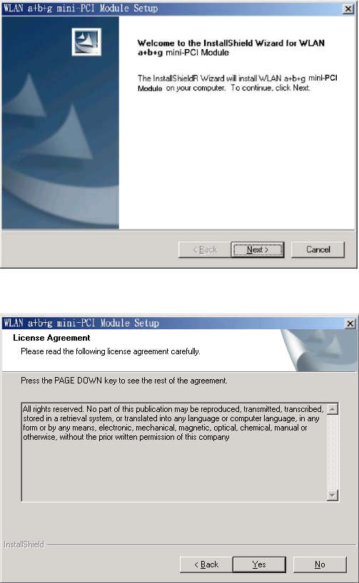
1. Insert the Installation Software CD into the CD-Rom Drive.
2. Click “Next”.
3. Read the License Agreement and click “Yes”.
7
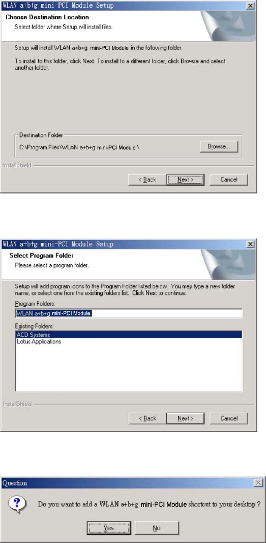
4. Click “Next” to continue or click “Browse” to choose a destination folder.
5. Click “Next”.
6. Click “Yes” to create a shortcut icon on your desktop.
8
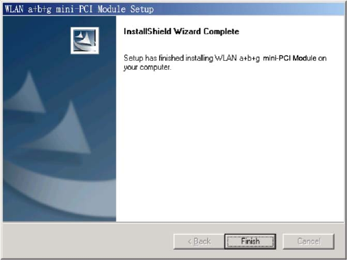
7. Click “Finish”.
8. You should now see a shortcut icon on your desktop.
9
2.2 Additional Setup Processes
During software installation procedure, each operating system may prompt different
specific options:
1. Windows 98SE: The system will request the original Windows CD during the
installation process. When the installation is finished, you’ll have to restart your
computer.
2. Windows Me: Please restart your computer when the installation is finished.
3. Windows 2000/XP: Select “Install the software automatically” when the window
with this option appears, and then click “Next” to continue installation.
10
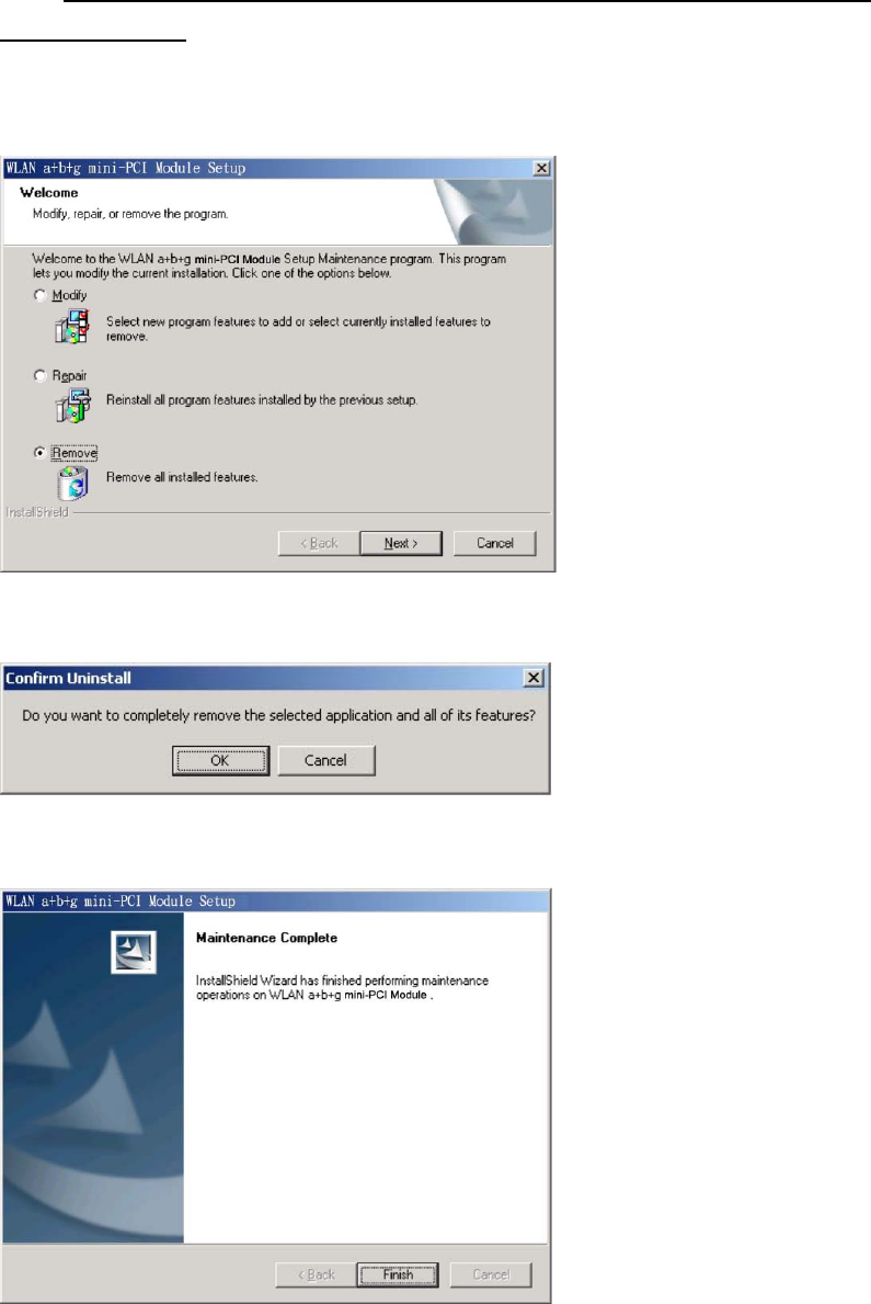
2.3 Uninstallation
Note! Before uninstallation, please close all running programs.
1. Click Start>Programs>WLAN a+b+g mini-PCI Module >UnInstall WLAN a+b+g
mini-PCI Module.
2. Choose “Remove”. Click “Next”.
3. Click “OK” to start Uninstall.
4. Click “Finish”. Uninstall is now completed.
11
3. Connecting to an Existing Network
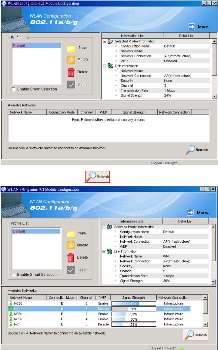
1. Double click the shortcut icon of WLAN a+b+g mini-PCI Module on the desktop,
and the Configuration window appears.
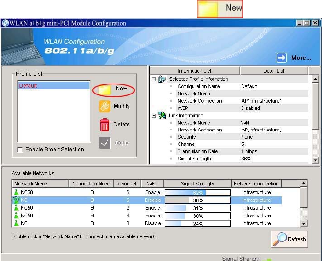
2. Click on the Refresh button to list all available networks.
12
Note! To automatically connect to the network with the strongest signal, select
Enable Smart Selection. Any displays in Profile List.
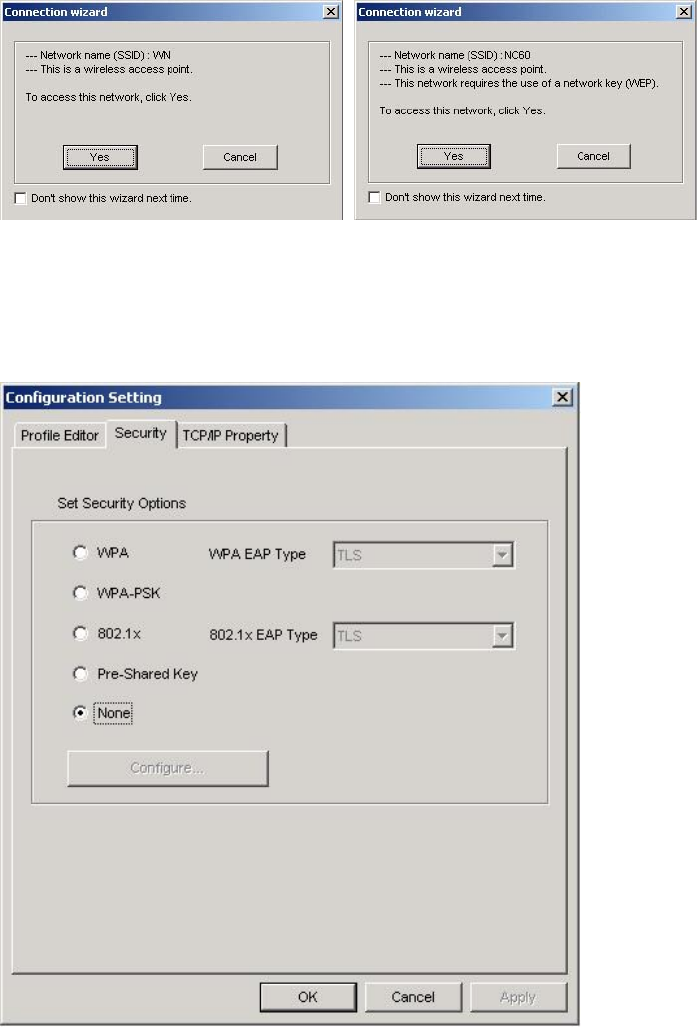
3. From the list of “Available Networks”, choose one network by double clicking the
Network Name. One of the following dialog boxes appears. Click “Yes” to
continue.
4. If the chosen network has security enabled, the Security tab displays. Select the
security option used by the network. Contact the network administrator for the
correct settings.
13
5. If selecting WPA or 802.1X, select the EAP type, then click on the Configure
button to select the certificate.
6. If selecting WPA-PSK, click on the Configure button to enter the PassPhrase.
14
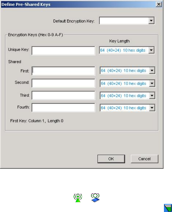
7. If selecting Pre-Shared Key, click on the Configure button to enter the correct
Encryption Keys.
Key entry method:
a.10hex digits: User must enter 10 hexadecimal digits.
The hexadecimal define is "0-9" and "A-F".
ex: 123456abc
b.5 chars: User must enter 5 characters. ex: ab3#@
c.13 chars: User must enter 13 characters.
ex: ab3#@kf08&kdk
d.16 chars: User must enter 16 characters.
ex: ab3#@kf08&kdk456
For WEP key, please contact with MIS administrator.
8. Click on OK (or Apply if using the other tabs) when done to save the settings.
9. Once connected (the icon or in front of the name of the Connected
Network), you can check the signal strength from the icon in the Windows
System Tray.
15
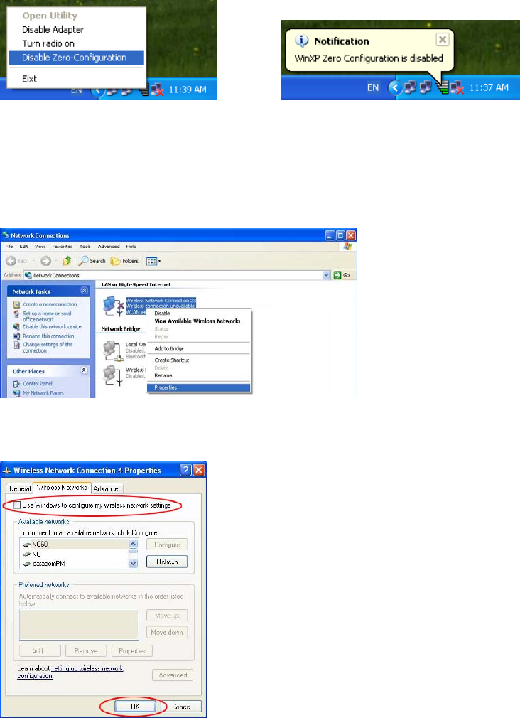
Additional Note for Windows XP
In Windows XP, it is recommended that you use the WLAN a+b+g mini-PCI Module
Configuration Utility. Before using the Utility, please follow the steps below to
disable the Windows XP Zero Configuration:
Option 1:
1. Double click the shortcut icon to open the Utility.
2. From the Windows System Tray, you should see the signal icon. Right-click it
and select “Disable Zero-Configuration”.
Option 2:
1. Go to “Control Panel” and double click “Network Connections”.
2. Right-click “Wireless Network Connection” of “WLAN a+b+g mini-PCI Module”,
and select “Properties”.
3. Select “Wireless Networks” tab, and uncheck the check box of “Use Windows to
configure my wireless network settings”, and then click “OK”.
16
4. Creating an Ad Hoc New Network
NOTE! Ad-hoc mode is available only for 802.11b/g. It is not available for 802.11a.
This is a client product and do not have radar detection function specified by FCC.
The software will not let you to use ad-hoc under 802.11a.
1. In the Configuration window, click New .
2. Select the “Profile Editor” tab.
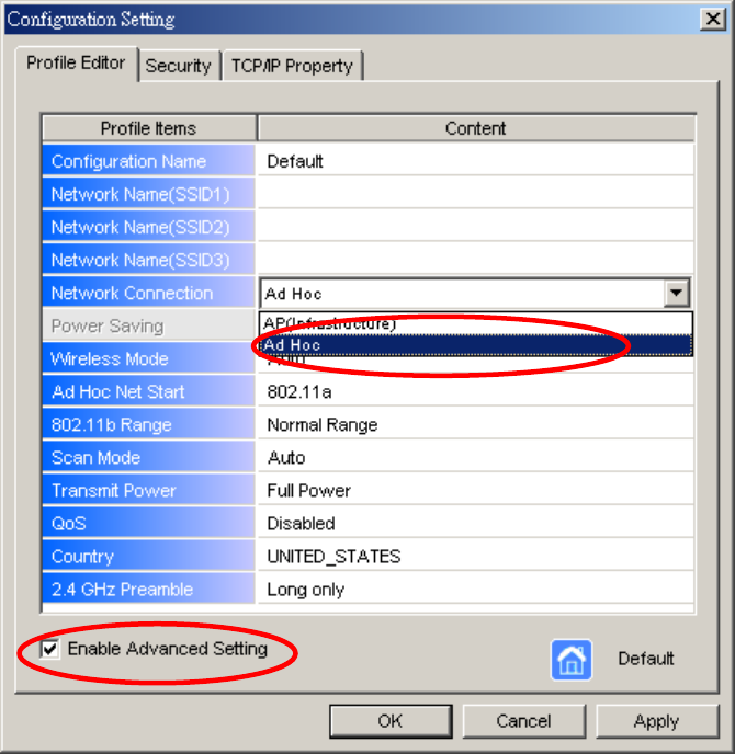
17
3. Choose the check box of Enable Advanced Setting to edit all settings.
4. If joining or creating an Ad-Hoc network, choose Ad Hoc.
5. Click OK (or Apply if using the other tabs) to save the settings.
For details of each setting, refer to Modifying a Wireless Network on page 20.
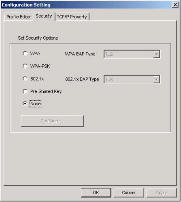
6. Click the Security tab. If not using security, select None.
18
7. If security is used, select Pre-Shared Key and click on the Configure button.
19
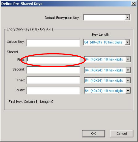
8. Enter an encryption key in the Shared: First field.
9. Click OK (or Apply if using the other tabs) to save the settings. The new
Network Name is listed in the Profile List.
The driver does not allow channel selection in Ad-Hoc mode. Instead, the driver
starts with an initial channel then checks channel status. If the channel is busy, the
driver automatically uses a different channel.
For details of each setting, please see chapter 5.
20
5. Modifying a Wireless Network
5.1 Infrastructure Mode and Ad Hoc Mode
You can set the Wireless Network Adapter to work in either Infrastructure mode or
Ad Hoc mode.
NOTE! Ad-hoc mode is available only for 802.11b/g. It is not available for 802.11a.
This is a client product and do not have radar detection function specified by FCC.
The software will not let you to use ad-hoc under 802.11a.
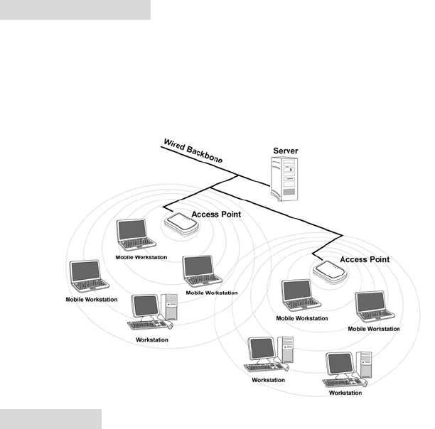
Infrastructure Mode
In infrastructure mode, devices communicate with each other by first going through
an Access Point (AP). Wireless devices can communicate with each other or can
communicate with a wired network. When one AP is connected to wired network
and a set of wireless stations, it is referred to as a BSS (Basic Service Set).
Ad Hoc Mode
Ad-hoc mode is also called “peer-to-peer mode” or “Independent Basic Service Set
(IBSS)”. In ad hoc mode, devices communicate directly with each other without
using an Access Point (AP).
NOTE! Ad-hoc mode is available only for 802.11b/g. It is not available for 802.11a.
This is a client product and do not have radar detection function specified by FCC.
The software will not let you to use ad-hoc under 802.11a.
21
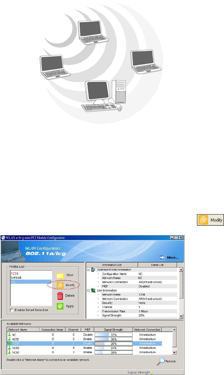
5.2 Modifying a Wireless Network
1. Open “WLAN a+b+g mini-PCI Module Configuration” by double clicking the
shortcut icon on the desktop.
Note! If there’s no network name listed in the “Profile List”, click Refresh
button and double click a Network Name from Available Networks.
The chosen Network Name is listed in the Profile List.
2. From the Profile List, select one Profile and click Modify button .
22
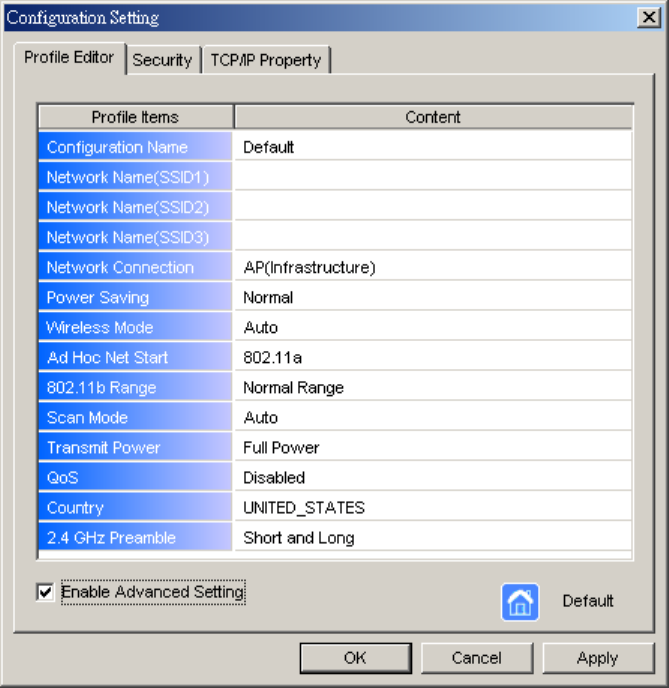
3. Select Profile Editor tab and edit the settings. Click OK to save the
modifications.
Configuration Name: This name identifies the configuration. This name
should be unique.
Network Name (SSID1) (SSID2) (SSID3): The name of the wireless
network. This name cannot be longer than 32 characters. If the field is
set to be “ANY” or is left blank, your computer will connect to an AP with
the best signal strength.
Network Connection: Specifies the mode of the network. Two options
are “Infrastructure” and “Ad Hoc”.
Power Saving: Minimizes power consumption while maintaining network
connectivity and high data transfer performance. In Ad Hoc mode, Power
Savings function cannot be enabled. The power management options are:
• Off: PC Card is powered up at all times.
• Normal: PC Card sleeps less often and stays asleep for a shorter period.
• Maximum: PC Card sleeps more frequently and stays asleep as much as
possible.
Wireless Mode: Three options are “802.11b”, “802.11a”, “802.11g”,
23
“Super A”, “Super G” or “Auto”. “Auto” allows the use of either 802.11a,
802.11g or 802.11b mode.
NOTE! Ad-hoc mode is available only for 802.11b/g. It is not available
for 802.11a. This is a client product and do not have rador detection
function specified by FCC. The software will not let you to use ad-hoc
under 802.11a.
Ad Hoc Net Start: Specifies a band to establish an Ad Hoc network if no
matching SSID is found. Options available are the following: 802.11b and
802.11g.
NOTE! Ad-hoc mode is available only for 802.11b/g. It is not available
for 802.11a. This is a client product and do not have radar detection
function specified by FCC. The software will not let you to use ad-hoc
under 802.11a.
802.11b Range: Options are Normal Range and Extended Range. This
function can let user to determine the transfer range in 802.11b mode.
Extended Range can prolong the transfer range with a lower data
transmitting rate.
Scan Mode: Options are Active Scan, Passive Scan and Auto. In Active
Scan, the driver sends out the probe request frames from each channel and
collects the response frames from the responding. In Passive Scan, the
driver scan each requested channel, listening the beacons on each channel.
Transmit Power: This setting allows you to change the output power of the
PC Card to increase or decrease the coverage area.
QoS: Disables or enables the PC Card to cooperate in a network using QoS
(Quality of Service).
2.4 GHz Preamble: Allows Ad-Hoc compatibility with other 2.4 GHz
devices. Two options are Short and Long and Long only. Use Long Only
when configuring the client for an 802.11b RoamAbout AP wireless
network.
24
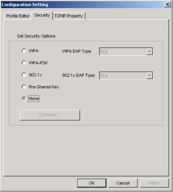
4. Select Security tab and choose the security mode.
Note! Check with your Network Administrator for the security features supported
by your AP.
WPA: Enables the use of WiFi protected Access (WPA). This option
requires IT administration.
a) Select WPA to open the WPA EAP drop-down menu. The options
includes TLS and PEAP.
b) Click on the Configure button and complete the configuration
information in the Define Certificate dialog.
WPA-PSK: Enables the WPA-Pre Shared Key (PSK). Click on the
Configure button and complete the configuration information in the WPA
Passphrase dialog.
802.1x: Enables 802.1x security. This option requires IT administration.
a) Select 802.1x to open the 802.1x EAP drop-down menu. The options
include TLS and PEAP.
b) Click on the Configure button and complete the configuration
information in the Define Certificate dialog.
25
Pre-Shared Key: Enables the use of pre-shared keys that are defined on the
AP and the station.
a) Select the Pre-Shared Key radio button.
b) Click on the Configure button and complete the configuration
information in the Define Certificate dialog.
None: No security.
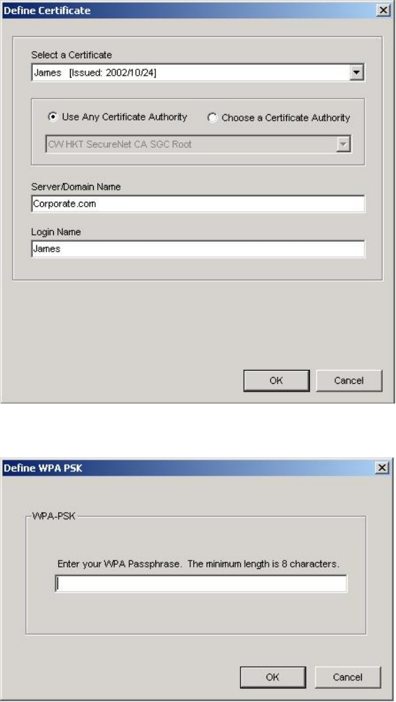
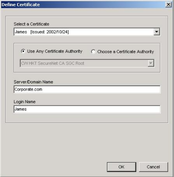
5. Define the Certificate.
Select a Certificate: Select the Certificate to Authenticate to the RADIUS
server from the drop-down menu.
Use any Certificate Authority: The Default Setting. Select this radio
button to use any Certificate Authority (CA) for authentication.
Choose a Certificate Authority: Select this radio button to choose the
desired Certificate Authority for authentication from the drop-down menu.
Server/Domain Name: The the RADIUS server name or the domain name
used for the network access.
Login Name: The username used to log into the server or domain.
Define User Information (PEAP): Click on the Define User Information
button and complete the configuration information in the Define User
Information dialog.
26
6. If selecting WPA-PSK, click on the Configure button to enter the PassPhrase.
The PassPhrase must be a minimum of 8 printable ASCII characters. The
PassPhrase should be at least 20 characters to make it more difficult for an
attacker to decipher the key.
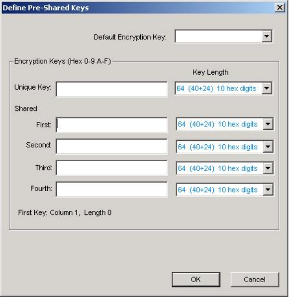
7. If selecting Pre-Shared Key, click on the Configure button to enter the
Encryption Keys.When finished, click OK. For WEP key, please contact with
MIS administrator.
Key Entry Method: Determines the entry method for the key. Hexadecimal
(0-9, A-F) or ASCII text (all keyboard characters).
Default Encryption Key: Allows you to choose one encryption key (First,
Second, Third, or Fourth) as the transmit key, which encrypts transmissions
from the PC Card.
Unique Key: Defines the per-session encryption key for the current network
configuration. Not used in Ad-Hoc mode.
Shared Keys: Use these fields to enter the wireless network’s encryption keys.
The keys must be in the correct position (First, Second, Third, or Fourth).
Key Length: Defines the length of each encryption key.
o For 40/64 bit (enter 10 digits for hexadecimal or 5 characters for ASCII)
o For 104/128 bit (Enter 26 digits for hexadecimal or 13 characters for ASCII)
27
When the length is changed, the number of available characters in the field
automatically changes. If a previously entered key is too long, the key is
automatically truncated to fit. If the key length is increased again, the key does
not update to the previous value.
8. Click OK to save the settings.
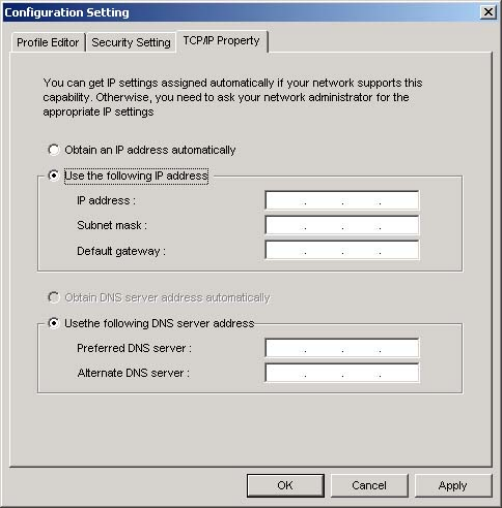
9. Select “TCP/IP Property” tab. Enter the settings and click “OK” to save the
settings.
If the network uses DHCP server, choose Obtain an IP address automatically.
If the network does not use DHCP server, choose Use the following IP address
to set the relative settings. For the IP configuration information, please contact
the network administrator.
28
5.3 Default Settings Windows XP Zero-Configuration
You may also choose the default parameters and directly proceed to Windows XP
zero-configuration through the steps below:
1. Go to “Control Panel” and open “Network Connections”.
2. Right-click the Wireless Network Connection of “WLAN a+b+g mini-PCI
Module”, and make sure this connection is Enabled.
3. Right-click the Wireless Network Connection of “WLAN a+b+g mini-PCI
Module”, and then click “Properties”.
4. Select “Wireless Networks” tab and select “Use Windows to configure my
wireless network settings” check box.
Note! Clear the check box of “Use Windows to configure my wireless network
settings” will disable automatic wireless network configuration.
29
Appendix A: FAQ about WLAN
1. Can I run an application from a remote computer over the wireless network?
This will depend on whether or not the application is designed to be used over a
network. Consult the application’s user guide to determine whether it supports
operation over a network.
2. Can I play computer games with other members of the wireless network?
Yes, as long as the game supports multiple players over a LAN (local area network).
Refer to the game’s user guide for more information.
3. What is Spread Spectrum?
Spread Spectrum technology is a wideband radio frequency technique developed by
the military for use in reliable, secure, mission-critical communications systems. It is
designed to trade off bandwidth efficiency for reliability, integrity, and security. In
other words, more bandwidth is consumed than in the case of narrowband
transmission, but the trade-off produces a signal that is, in effect, louder and thus
easier to detect, provided that the receiver knows the parameters of the
spread-spectrum signal being broadcast. If a receiver is not tuned to the right
frequency, a spread-spectrum signal looks like background noise. There are two main
alternatives, Direct Sequence Spread Spectrum (DSSS) and Frequency Hopping
Spread Spectrum (FHSS).
4. What is DSSS? What is FHSS? And what are their differences?
Frequency-Hopping Spread-Spectrum (FHSS) uses a narrowband carrier that changes
frequency in a pattern that is known to both transmitter and receiver. Properly
synchronized, the net effect is to maintain a single logical channel. To an unintended
receiver, FHSS appears to be short-duration impulse noise. Direct-Sequence
Spread-Spectrum (DSSS) generates a redundant bit pattern for each bit to be
transmitted. This bit pattern is called a chip (or chipping code). The longer the chip,
the greater the probability that the original data can be recovered. Even if one or more
bits in the chip are damaged during transmission, statistical techniques embedded in
the radio can recover the original data without the need for retransmission. To an
unintended receiver, DSSS appears as low power wideband noise and is rejected
(ignored) by most narrowband receivers.
30
5. Would the information be intercepted while transmitting on air?
WLAN features two-fold protection in security. On the hardware side, as with Direct
Sequence Spread Spectrum technology, it has the inherent security feature of
scrambling. On the software side, WLAN offers the encryption function (WEP) to
enhance security and access control.
6. What is WEP?
WEP is Wired Equivalent Privacy, a data privacy mechanism based on a 64-bit or
128-bit shared key algorithm, as described in the IEEE 802.11 standard.
7. What is infrastructure mode?
When a wireless network is set to infrastructure mode, the wireless network is
configured to communicate with a wired network through a wireless access point.
8. What is roaming?
Roaming is the ability of a portable computer user to communicate continuously
while moving freely throughout an area greater than that covered by a single access
point. Before using the roaming function, the workstation must make sure that it is the
same channel number with the access point of dedicated coverage area.
To achieve true seamless connectivity, the wireless LAN must incorporate a number
of different functions. Each node and access point, for example, must always
acknowledge receipt of each message. Each node must maintain contact with the
wireless network even when not actually transmitting data. Achieving these functions
simultaneously requires a dynamic RF networking technology that links access points
and nodes. In such a system, the user’s end node undertakes a search for the best
possible access to the system. First, it evaluates such factors as signal strength and
quality, as well as the message load currently being carried by each access point and
the distance of each access point to the wired backbone. Based on that information,
the node next selects the right access point and registers its address. Communications
between end node and host computer can then be transmitted up and down the
backbone. As the user moves on, the end node’s RF transmitter regularly checks the
system to determine whether it is in touch with the original access point or whether it
should seek a new one. When a node no longer receives acknowledgment from its
original access point, it undertakes a new search. Upon finding a new access point, it
then re-registers, and the communication process continues.

31
Appendix B: Specification
Electric Characteristics:
Category Key Specifications
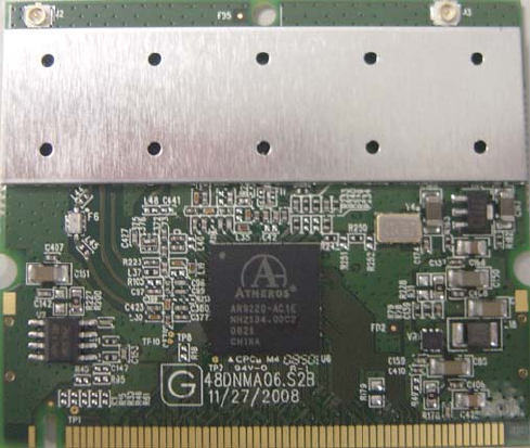
Main
Chipset
Atheros® Communication AR9220 dual band configurable radio
Frequency
Range
USA: 2.400 ~ 2.483 GHz, 5.15 ~ 5.35 GHz, 5.5 ~ 5.7 GHz, 5.725 ~ 5.825
GHz
Europe: 2.400 ~ 2.483 GHz, 5.15 ~ 5.35 GHz, 5.47 ~ 5.725 GHz
Japan: 2.400 ~ 2.497 GHz, 5.15 ~ 5.35 GHz, 5.47 ~ 5.725 GHz
China: 2.400 ~ 2.483 GHz, 5.725 ~5.85 GHz
(Note: A DNMA-92 radio is capable to be operated within FCC DFS2 band or ETSI/EC DFS band, or other
countries which is regulating or is planning to regulate mid-5 GHz band. The usage of mid-5 GHz band is
subject to the regulatory approval alone with the resided devices like Access Point or Router. )
Host
Interface
Mini-PCI form factor; Mini-PCI Version 1.0 type 3A
Channels
support
802.11 b/g/n
o US/Canada: 11 (1 ~ 11)
o Major European country: 13 (1 ~ 13)
o France: 4 (10 ~ 13)
o Japan: 11b: 14 (1~13 or 14th), 11g/n: 13 (1 ~ 13)
o China: 13 (1 ~ 13)
802.11 a/n
o US/Canada: 23 non-overlapping channels; 36, 40, 44, 48, 52, 56, 60, 64,
100, 104, 108, 112, 116, 120, 124, 128, 132, 136, 140, 149, 153, 157, 161
o Europe: 19 non-overlapping channel; 36, 40, 44, 48, 52, 56, 60, 64, 100, 104,
108, 112, 116, 120, 124, 128, 132, 136, 140
o Japan: 19 non-overlapping channels; 36, 40, 44, 48, 52, 56, 60, 64, 100, 104,
108, 112, 116, 120, 124, 128, 132, 136, 140
o China: 5 non-overlapping channels; 149, 153, 157, 161, 165
Operation
Voltage
3.3V +/-5%

32
Typical
Current
Consumpti
on
802.11a 802.11b 802.11g 802.11n(2.4GHz) 80
2
Avg/Max (mA) Avg/Max (mA) Avg/Max (mA) Avg/Max (mA) Av
g
Continue Tx 617/744 566/691 706/859 579/712 59
1
FTP Tx 356/667 363/700 271/743 358/741 37
9
FTP Rx 224/590 156/685 165/721 184/726 28
7
Standby mod
e
180/312 142/254 143/259 142/256 20
5
The maximum current consumption would be impacted by radiation environment an
d
Condition: 2T2R @25 o C ( with +15 /-15% tolerance)

33
RF Output
Power (dB)
(Typical
composite
power )
Tolerance:
+2/-2 dB
@ 25 oC
+3/-3 dB
@ 0 & 60
oC
802.11a
Frequency 6-24_Target 36_Target 48_Target 54_Target
5180 21 20 19 17
5320 21 20 19 17
5700 21 20 19 16
5825 21 20 19 16
802.11b
Frequency 1_Target 2_Target 5.5_Target 11_Target
2412 20 21 21 21
2484 19 20 21 21
802.11g
Frequency 6-24_Target 36_Target 48_Target 54_Target
2412 23 22 21 19
2442 23 22 21 19
2472 23 22 21 19
802.11a/n
Freq. Range: 5GHz/HT20:
Frequency MCS 0/8 MCS 1/9 MCS 2/10 MCS 3/11 MCS 4/12 MCS 5/13 MCS 6
/
5180 21 21 21 20 20 20 19
5240 21 21 21 20 20 20 19
5320 21 21 21 20 20 20 19
5500 20 20 20 20 20 20 19
5700 19 19 19 19 19 19 18
5745 19 19 19 19 19 19 18
5825 19 19 19 19 19 19 18
Freq. Range: 5GHz/HT40:
Frequency MCS 0/8 MCS 1/9 MCS 2/10 MCS 3/11 MCS 4/12 MCS 5/13 MCS 6
/
5190 19 19 19 19 19 19 18
5230 19 19 19 19 19 19 18
5270 19 19 19 19 19 19 18
5510 18 18 18 18 18 18 18
5670 18 18 18 18 18 18 17
5755 18 18 18 18 18 18 17
5795 18 18 18 18 18 18 17
802.11gn
Freq. Range: 2GHz/HT20:
Frequency MCS 0/8 MCS 1/9 MCS 2/10 MCS 3/11 MCS 4/12 MCS 5/13 MCS 6
/
2412 21 21 21 21 21 21 19
2442 21 21 21 21 21 21 19
2472 21 21 21 21 21 21 19
Freq. Range: 2GHz/HT40:
Frequency MCS 0/8 MCS 1/9 MCS 2/10 MCS 3/11 MCS 4/12 MCS 5/13 MCS 6
/
2422 21 21 21 21 20 20 18
2442 20 20 20 20 20 20 18
2462 20 20 20 20 19 19 18

34

35
EVM
802.11a Data Rate Relative constellation error (dB) Relative constellation
IEEE Spec (1Tx) Typical/Maximu
m
6M -5 -25/-16
9M -8 -25/-16
12M -10 -25/-16
18M -13 -26/-16
24M -16 -24/-19
36M -19 -27/-22
48M -22 -28/-23
54M -25 -28/-25
802.11b Data Rate Relative constellation error (dB) Relative constellation
IEEE Spec (1Tx) Typical/Maximu
m
1M -10 -18/-15
5.5M -10 -18/-15
11M -10 -18/-15
802.11
g
Data Rate Relative constellation error (dB) Relative constellation
IEEE Spec (1Tx) Typical/Maximu
m
6M -5 -24/-16
9M -8 -25/-16
12M -10 -25/-16
18M -13 -26/-16
24M -16 -23/-19
36M -19 -29/-22
48M -22 -31/-23
54M -25 -31/-25
802.11n
g
Data Rate Relative constellation error (dB) Relative constellation
HT20 IEEE Spec (1Tx) Typical/Maximu
m
MCS0 -5 -30/-16
MCS1 -10 -30/-16
MCS2 -13 -30/-16
MCS3 -16 -30/-19
MCS4 -19 -30/-22
MCS5 -22 -31/-23
MCS6 -25 -31/-25
MCS7 -28 -31/-27
MCS8 -5 -30/-16
MCS9 -10 -30/-16
MCS10 -13 -30/-16
MCS11 -16 -30/-19
MCS12 -19 -30/-22
MCS13 -22 -30/-23
MCS14 -25 -30/-25
MCS15 -28 -30/-27
HT40 MCS0 -5 -30/-16
MCS1 -10 -30/-16
MCS2 -13 -30/-16
MCS3 -16 -30/-19
MCS4 -19 -30/-22
MCS5 -22 -30/-23
MCS6 -25 -30/-25
MCS7 -28 -30/-27
MCS8 -5 -30/-16
MCS9 -10 -30/-16
MCS10 -13 -30/-16
MCS11 -16 -30/-19
MCS12 -19 -30/-22
MCS13 -22 -30/-23
MCS14 -25 -30/-25
MCS15 -28 -30/-27
802
.
11
n
a
Data Rate Relative constellation error (dB) Relative constellation

36
Sensitivity
802.11
a
Data Rate IEEE Spec (1 Rx dBm) Typical/Maximum (
2
6M -82 -95/-91
9M -81 -95/-91
12M -79 -94/-90
18M -77 -92/-88
24M -74 -88/-84
36M -70 -85/-81
48M -66 -81/-77
54M -65 -79/-75
802.11
b
Data Rate IEEE Spec (1 Rx dBm) Typical/Maximum (
2
1M -82 -95/-91
5.5M -80 -95/-91
11M -76 -91/-87
802.11
g
Data Rate IEEE Spec (1 Rx dBm) Typical/Maximum (
2
6M -82 -95/-91
9M -81 -95/-91
12M -79 -94/-90
18M -77 -93/-89
24M -74 -90/-86
36M -70 -86/-82
48M -66 -82/-78
54M -65 -80/-76
802.11n
g
Data Rate IEEE Spec (1 Rx dBm) Typical/Maximum (
2
HT20 MCS0 -82 -95/-91
MCS1 -79 -94/-90
MCS2 -77 -92/-88
MCS3 -74 -88/-84
MCS4 -70 -85/-81
MCS5 -66 -80/-76
MCS6 -65 -79/-75
MCS7 -64 -77/-73
HT40 MCS0 -79 -90/-86
MCS1 -76 -90/-86
MCS2 -74 -89/-85
MCS3 -71 -85/-81
MCS4 -67 -82/-78
MCS5 -63 -78/-74
MCS6 -62 -77/-73
MCS7 -61 -74/-71

37
802.11n
a
Data Rate IEEE Spec (1 Rx dBm) Typical/Maximum(
2
HT20
MCS0 -82 -95/-91
MCS1 -79 -93/-89
MCS2 -77 -90/-86
MCS3 -74 -87/-83
MCS4 -70 -84/-80
MCS5 -66 -80/-76
MCS6 -65 -79/-75
MCS7 -64 -77/-73
HT40
MCS0 -79 -91/-87
MCS1 -76 -90/-86
MCS2 -74 -87/-83
MCS3 -71 -84/-80
MCS4 -67 -82/-78
MCS5 -63 -78/-74
MCS6 -62 -76/-72
MCS7 -61 -74/-70
Operation
Distance
802.11a
o Outdoor: 50 m @54Mbps, 300 m @6Mbps
o Indoor: 30 m @54Mbps, 100 m @6Mbps
802.11b
o Outdoor: 150 m @11Mbps, 300 m @1Mbps
o Indoor: 30 m @11Mbps, 100 m @1Mbps
802.11g
o Outdoor: 50 m @54Mbps, 300 m @6Mbps
o Indoor: 30 m @54Mbps, 100 m @6Mbps
802.11n
o Outdoor: 250 m @6.5Mbps (MCS0: 1 Nss/20MHz BW)
o 30m @130Mbps (MCS15: 2 Nss/20MHz BW)
o 30m @300Mbps (MCS15: 2 Nss/40MHz BW)
o Indoor: 100 m @6.5Mbps (MCS0: 1 Nss/20MHz BW)
o 20m @130Mbps (MCS15: 2 Nss/20MHz BW)
o 20m @300Mbps (MCS15: 2 Nss/40MHz BW)
( Notes :Estimated range are based on 2dB dipole antenna. The real operational distance is depending on (Access
Point) system efficiency and antenna performance. )

38
PCB
Dimension
50.8mm (L/H) x 59.6mm (W) x 1.0mm (T)
Data Rate 802.11b: 1, 2, 5.5, 11Mbps
802.11g: 6, 9, 12, 18, 24, 36, 48, 54Mbps
802.11n: @800GI(400GI)
o 20MHz BW
1 Nss: 65(72.2)Mbps maximal
2 Nss: 130(144.4)Mbps maximal
o 40MHz BW
1 Nss: 135(150)Mbps maximal
2 Nss: 270(300)Mbps maximal
Operation
Temperatur
e
0o ~ 60o C
Storage
Temperatur
e
-20o ~ 80o C
Wi-Fi
Alliance
WECA Compliant
Radio &
EMC
Certificate
US: 47 CFR 15, FCC Part 15 401~ Part 15. 407 (5150 ~ 5350 MHz &
5725~5825 MHz), Part 15.247 (5725~5850 MHz); FCC Part 15.247
(2400~2483.5 MHz), 47CFR 15, FCC-Class B, FCC Part 15.107 & Part
15.109;
Limited Module Level Approval,
Industry Canada: IC RSS210, RSS139-1, ICES-003; Limited Module Level
Approval
ETSI, EN301893, EN60950 (Europe); EN 301.893, EN 300.328, & EN
301489-1/17 EN 55022 & EN 55024;
Antenna
connector
2 x SMT ultra-miniature coaxial connectors (Hirose® U.FL connector)