Wistron NeWeb DNMA83 WLAN a/b/g/n mini-PCI Module User Manual
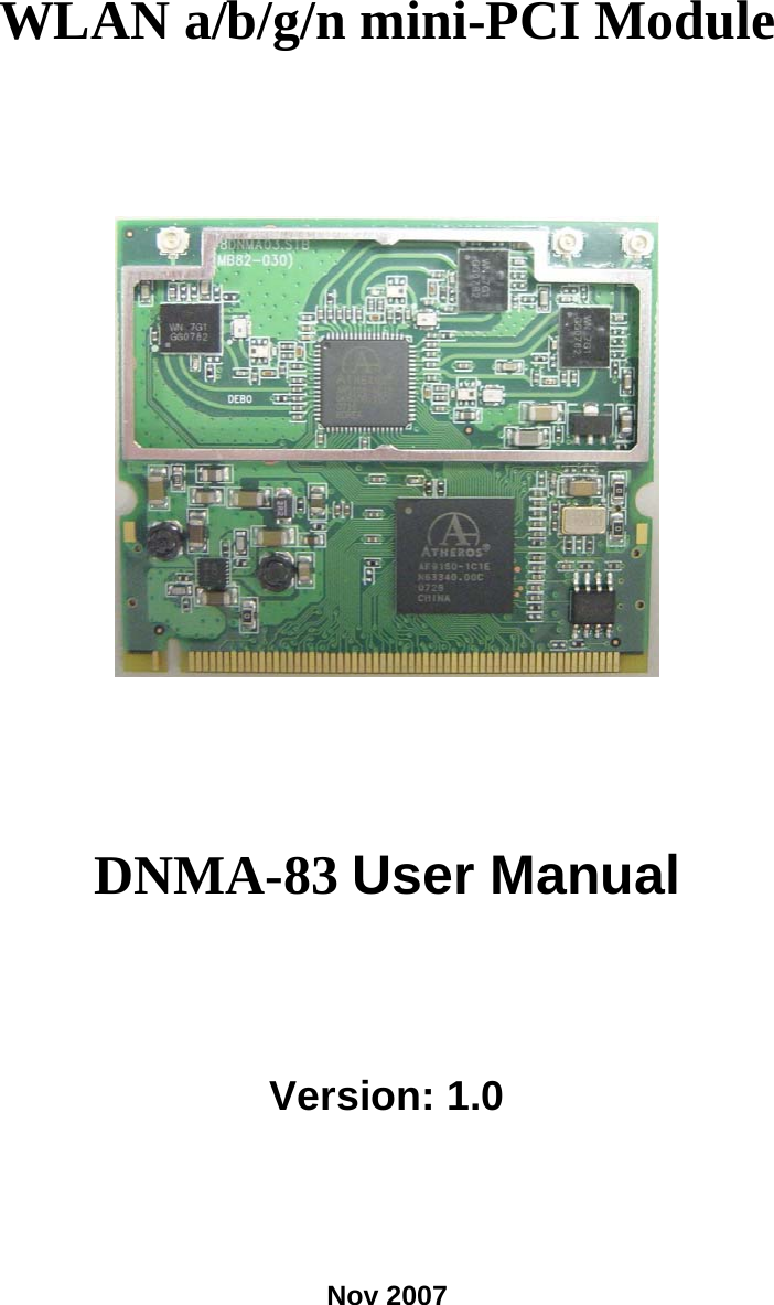
Wistron NeWeb Corporation WLAN a/b/g/n mini-PCI Module
UserManual.wiki
>
Wistron NeWeb
>
DNMA83 User Manual
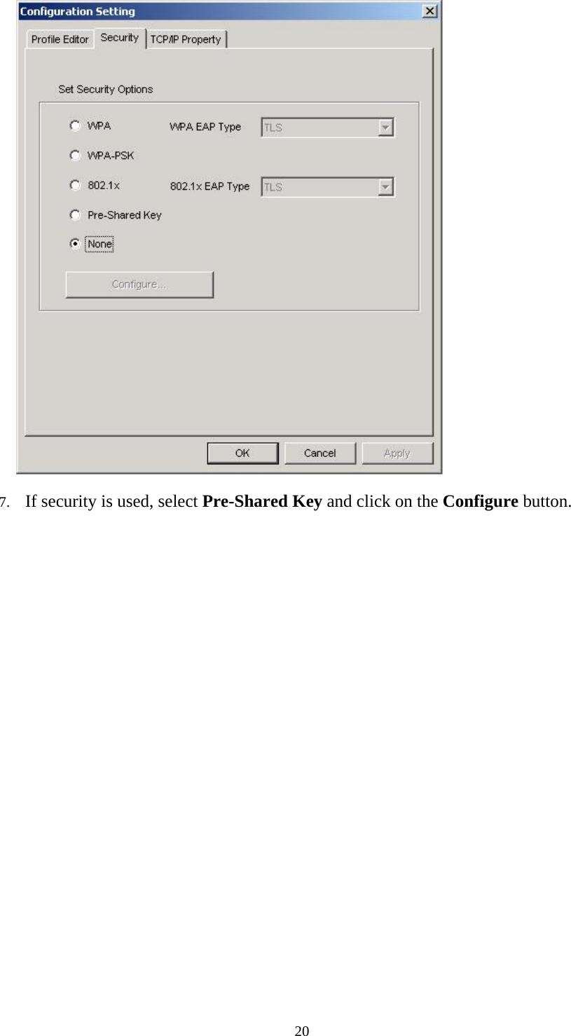
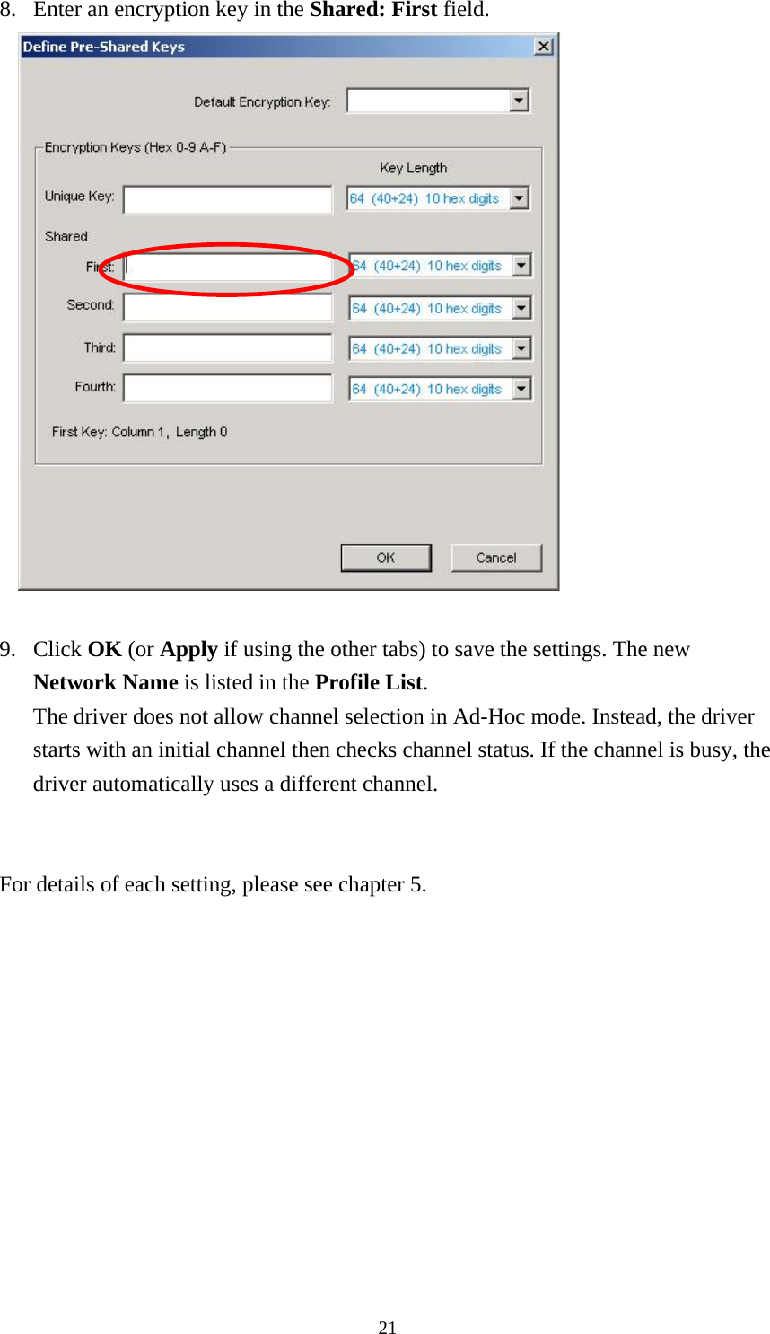
User Manual
Navigation menu
Upload a User Manual
Namespaces
Wiki Guide
HTML
PDF
Info
Views
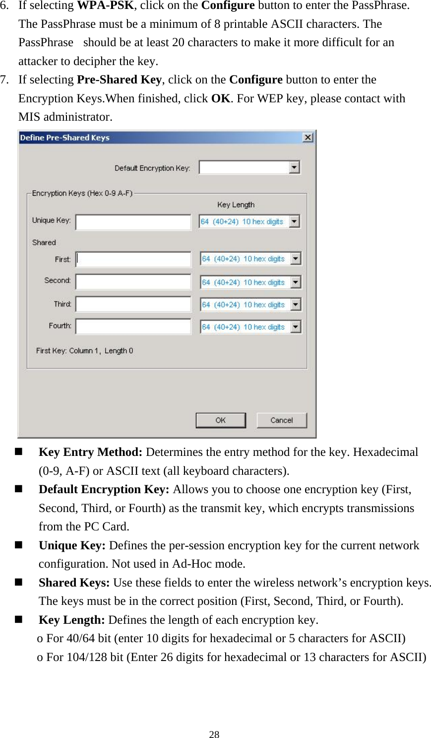
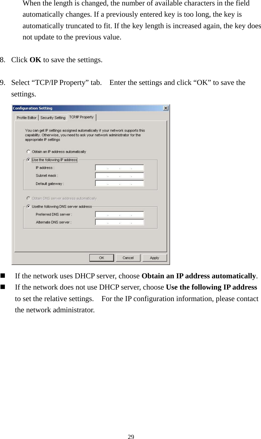
User Manual
Discussion / Help
Navigation