Wistron NeWeb DNMA84 WLAN mini PCI Module User Manual DNMA 84 Manual
Wistron NeWeb Corporation WLAN mini PCI Module DNMA 84 Manual
User Manual
WLAN b/g/n mini-PCI Module
DNMA-84 User Manual
Version: 1.0
May 2008
1
Copyright Statement
No part of this publication may be reproduced, stored in a retrieval system, or
transmitted in any form or by any means, whether electronic, mechanical,
photocopying, recording or otherwise without the prior writing of the publisher.
Windows™ 98SE/2000/ME/XP are trademarks of Microsoft® Corp.
Pentium is trademark of Intel.
All copyright reserved.
2
Federal Communication Commission Interference Statement
This equipment has been tested and found to comply with the limits for a Class
B digital device, pursuant to Part 15 of the FCC Rules. These limits are
designed to provide reasonable protection against harmful interference in a
residential installation. This equipment generates, uses and can radiate radio
frequency energy and, if not installed and used in accordance with
the instructions, may cause harmful interference to radio communications.
However, there is no guarantee that interference will not occur in a particular
installation. If this equipment does cause harmful interference to radio or
television reception, which can be determined by turning the equipment off and
on, the user is encouraged to try to correct the interference by one of the
following measures:
- Reorient or relocate the receiving antenna.
- Increase the separation between the equipment and receiver.
- Connect the equipment into an outlet on a circuit different from that to which
the receiver is connected.
- Consult the dealer or an experienced radio/TV technician for help.
FCC Caution: To assure continued compliance, (example - use only shielded
interface cables when connecting to computer or peripheral devices) any
changes or modifications not expressly approved by the party responsible for
compliance could void the user's authority to operate this equipment.
This device complies with Part 15 of the FCC Rules. Operation is subject to the
following two conditions:
(1) This device may not cause harmful interference, and
(2) This device must accept any interference received, including interference that may
cause undesired operation.
Country Code Statement
For product available in the USA/Canada market, only channel 1~11 can be
operated. Selection of other channels is not possible.
IMPORTANT NOTE:
This transmitter must not be co-located or operating in conjunction
with any other antenna or transmitter.
3
IMPORTANT NOTE:
This module is intended for OEM integrator. The OEM integrator is still
responsible for the FCC compliance requirement of the end product,
which integrates this module.
20cm minimum distance has to be able to be maintained between the
antenna and the users for the host this module is integrated into. Under
such configuration, the FCC radiation exposure limits set forth for an
population/uncontrolled environment can be satisfied.
Any changes or modifications not expressly approved by the
manufacturer could void the user's authority to operate this equipment.
USERS MANUAL OF THE END PRODUCT:
In the users manual of the end product, the end user has to be informed
to keep at least 20cm separation with the antenna while this end
product is installed and operated. The end user has to be informed that
the FCC radio-frequency exposure guidelines for an uncontrolled
environment can be satisfied. The end user has to also be informed that
any changes or modifications not expressly approved by the
manufacturer could void the user's authority to operate this equipment.
If the size of the end product is smaller than 8x10cm, then additional
FCC part 15.19 statement is required to be available in the users
manual: This device complies with Part 15 of FCC rules. Operation is
subject to the following two conditions: (1) this device may not cause
harmful interference and (2) this device must accept any interference
received, including interference that may cause undesired operation.
LABEL OF THE END PRODUCT:
The final end product must be labeled in a visible area with the following
" Contains TX FCC ID: NKR-DNMA84 ". If the size of the end product is
larger than 8x10cm, then the following FCC part 15.19 statement has to
also be available on the label: This device complies with Part 15 of
FCC rules. Operation is subject to the following two conditions: (1) this
device may not cause harmful interference and (2) this device must
accept any interference received, including interference that may cause
undesired operation.
4
IMPORTANT NOTE:
FCC Radiation Exposure Statement:
This equipment complies with FCC radiation exposure limits set forth for an
uncontrolled environment. This equipment should be installed and operated
with minimum distance 20cm between the radiator & your body.
"This device supports FCC Part 15, subpart E dynamic frequency selection
(DFS)."
"For the band 5150–5350 MHz this equipment must be used indoors only
to reduce potential for harmful interference to co-channel mobile
satellite systems."
“This device has been designed to operate with the antennas listed below,
and having a maximum gain of 1.82 dB. Antennas not included in this list or
having a gain greater than 1.82 dB are strictly prohibited for use with this
device. The required antenna impedance is 50 ohms."
“Operation is subject to the following two conditions: (1) this device
may not cause interference, and (2) this device must accept any
interference, including interference that may cause undesired operation
of the device."
The information is as follows:
This Class B digital apparatus complies with Canadian ICES-003.
Cet appareil num?rique de la classe B est conforme ? la norme NMB-003 du Canada.
-the maximum antenna gain permitted (for devices in the 5250-5350 MHz
and 5470-5725 MHz bands) to comply with the e.i.r.p. limit.
- the maximum antenna gain permitted (for devices in the 5725-5825 MHz
band) to comply with the e.i.r.p. limits specified for point-to-point
and non point-to-point operation as appropriate, as stated in section
A9.2(3)
- users should also be cautioned to take note that high power radars are
allocated as primary users (meaning they have priority) of 5250-5350 MHz
and 5650-5850 MHz and these radars could cause interference and/or damage
to LE-LAN devices.
Cet appareil numérique de la classe B est conforme à la norme NMB-003 du Canada.

5
Table of Contents
1. INTRODUCTION 6
2. DRIVER/UTILITY INSTALLATION / UNINSTALLATION 7
2.1 INSTALLATION .........................................................................................................7
2.2 ADDITIONAL SETUP PROCESSES............................................................................10
2.3 UNINSTALLATION................................................................................................... 11
3. CONNECTING TO AN EXISTING NETWORK 12
4. CREATING AN AD HOC NEW NETWORK 17
5. MODIFYING A WIRELESS NETWORK 21
5.1 INFRASTRUCTURE MODE AND AD HOC MODE .....................................................21
5.2 MODIFYING A WIRELESS NETWORK.....................................................................22
5.3 DEFAULT SETTINGS WINDOWS XP ZERO-CONFIGURATION................................29
5.4 SUPER A/G SETTING.......................................................... 錯誤! 尚未定義書籤。
APPENDIX A: FAQ ABOUT WLAN 30
APPENDIX B: SPECIFICATION 32
6
1. Introduction
Thank you for purchasing the WLAN b/g/n mini-PCI Module that provides the easiest
way to wireless networking. This User Manual contains detailed instructions in the
operation of this product. Please keep this manual for future reference.
System Requirements
A laptop PC contains:
- 32 MB memory or greater
- 300 MHz processor or higher
Microsoft® Win™2000/ME/98 Second Edition/XP
7
2. Driver/Utility Installation / Uninstallation
2.1 Installation
Note! The Installation Section in this User Manual describes the first-time installation
for Windows. To re-install the driver, please first uninstall the previously
installed driver. See Chapter 2.3 “Uninstallation” in this User Manual.
Follow the steps below to complete the driver/utility installation:
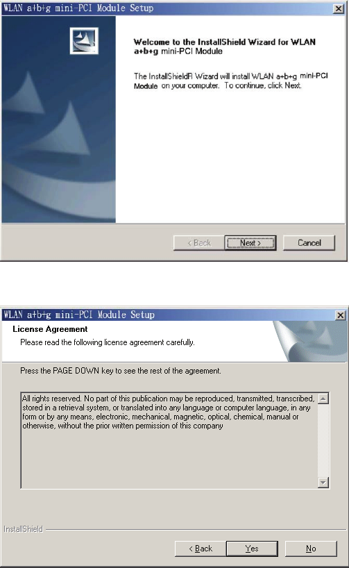
1. Insert the Installation Software CD into the CD-Rom Drive.
2. Click “Next”.
3. Read the License Agreement and click “Yes”.
8
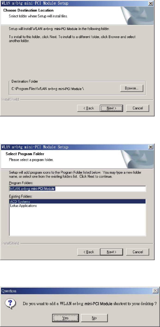
4. Click “Next” to continue or click “Browse” to choose a destination folder.
5. Click “Next”.
6. Click “Yes” to create a shortcut icon on your desktop.
9
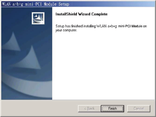
7. Click “Finish”.
8. You should now see a shortcut icon on your desktop.
10
2.2 Additional Setup Processes
During software installation procedure, each operating system may prompt different
specific options:
1. Windows 98SE: The system will request the original Windows CD during the
installation process. When the installation is finished, you’ll have to restart your
computer.
2. Windows Me: Please restart your computer when the installation is finished.
3. Windows 2000/XP: Select “Install the software automatically” when the window
with this option appears, and then click “Next” to continue installation.
11
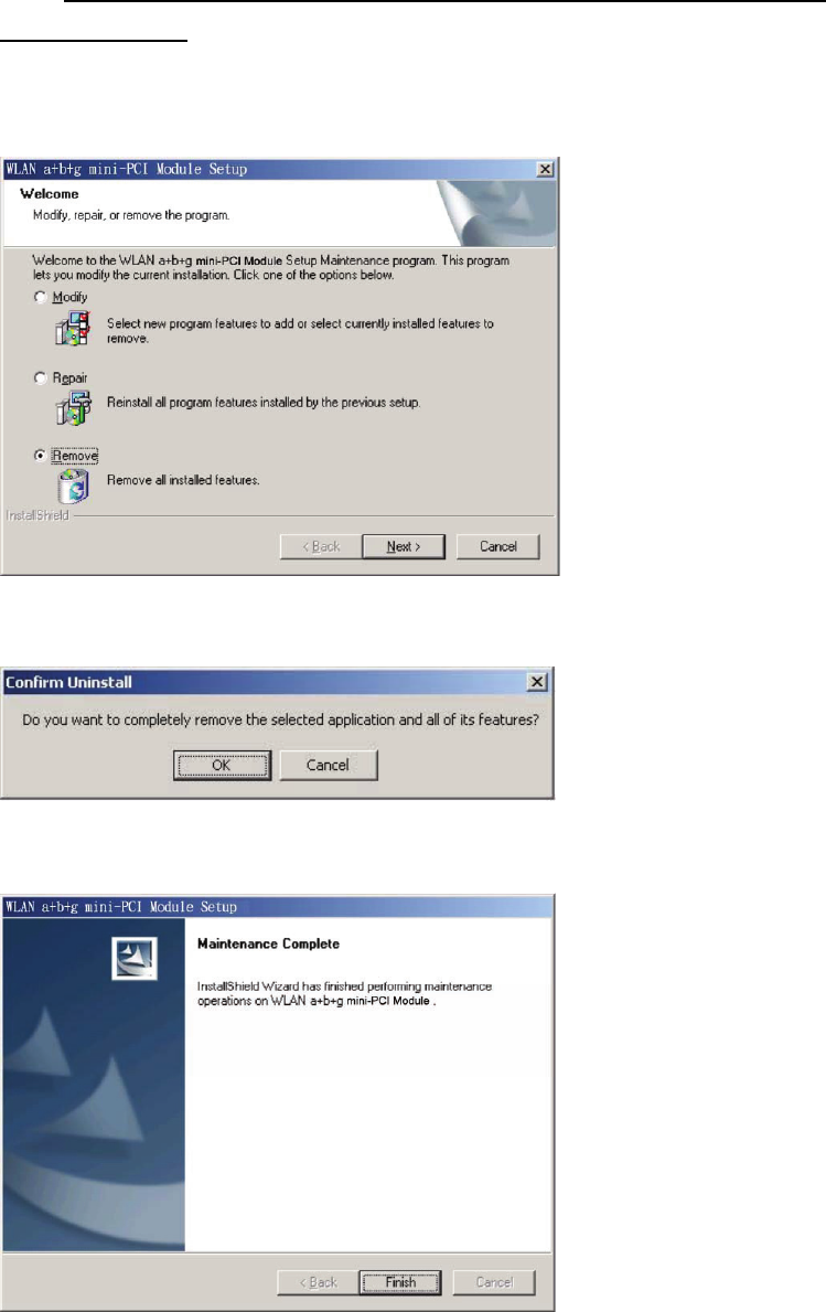
2.3 Uninstallation
Note! Before uninstallation, please close all running programs.
1. Click Start>Programs>WLAN b+g mini-PCI Module >UnInstall WLAN b+g
mini-PCI Module.
2. Choose “Remove”. Click “Next”.
3. Click “OK” to start Uninstall.
4. Click “Finish”. Uninstall is now completed.
12
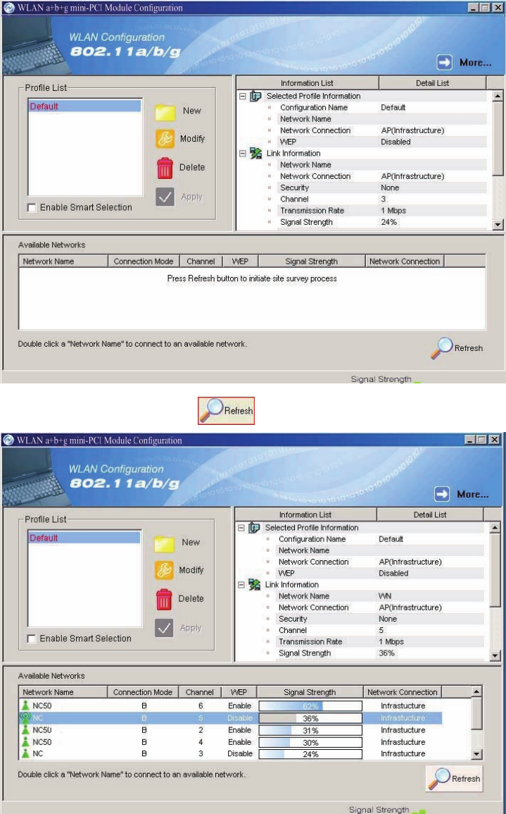
3. Connecting to an Existing Network
1. Double click the shortcut icon of WLAN b+g mini-PCI Module on the desktop,
and the Configuration window appears.
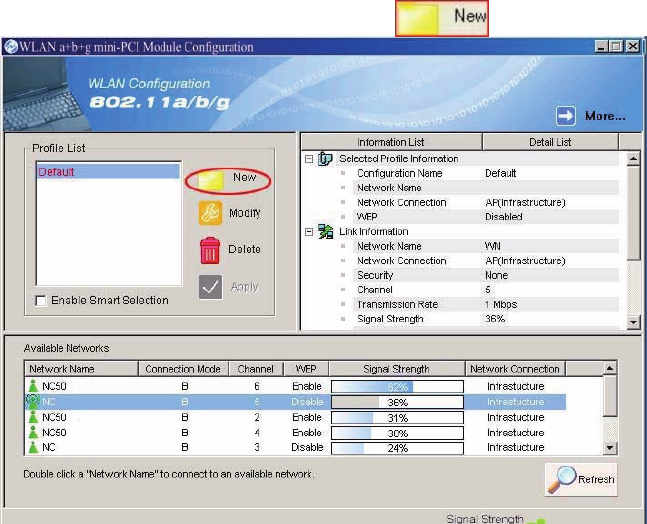
2. Click on the Refresh button to list all available networks.
13
Note! To automatically connect to the network with the strongest signal, select
Enable Smart Selection. Any displays in Profile List.
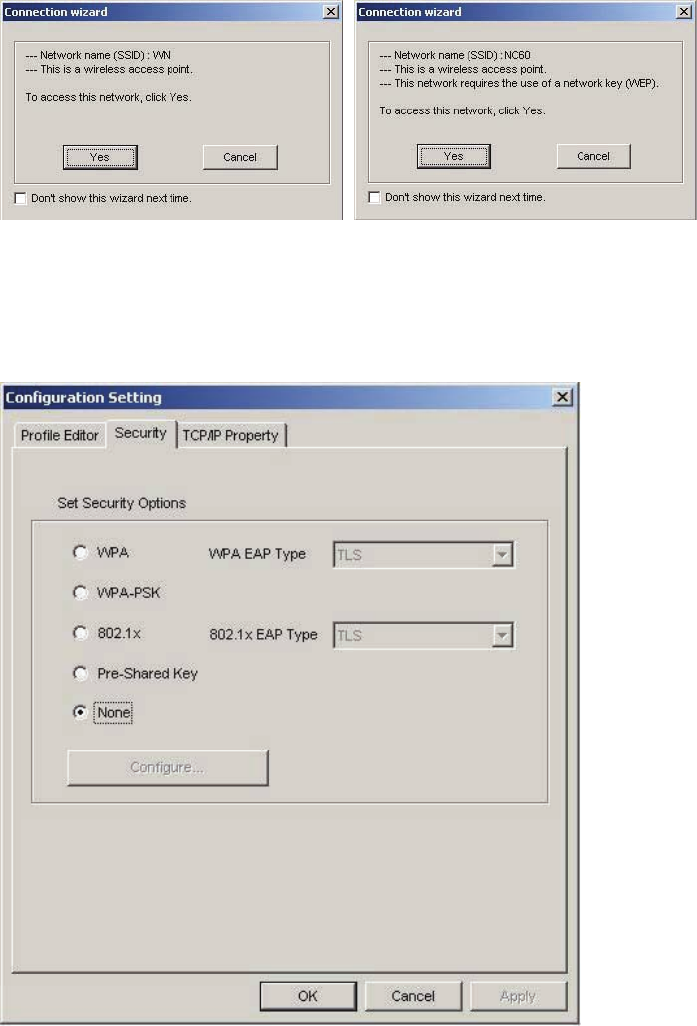
3. From the list of “Available Networks”, choose one network by double clicking the
Network Name. One of the following dialog boxes appears. Click “Yes” to
continue.
4. If the chosen network has security enabled, the Security tab displays. Select the
security option used by the network. Contact the network administrator for the
correct settings.
14
5. If selecting WPA or 802.1X, select the EAP type, then click on the Configure
button to select the certificate.
6. If selecting WPA-PSK, click on the Configure button to enter the PassPhrase.
15
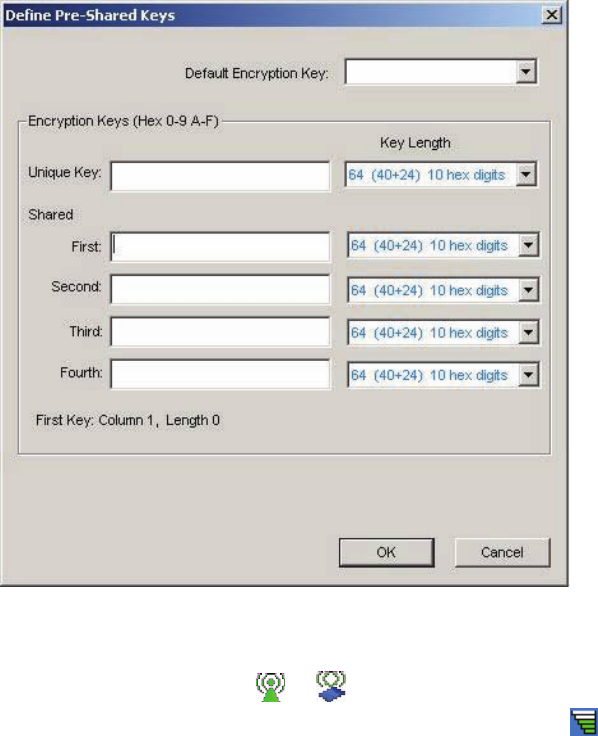
7. If selecting Pre-Shared Key, click on the Configure button to enter the correct
Encryption Keys.
Key entry method:
a.10hex digits: User must enter 10 hexadecimal digits.
The hexadecimal define is "0-9" and "A-F".
ex: 123456abc
b.5 chars: User must enter 5 characters. ex: ab3#@
c.13 chars: User must enter 13 characters.
ex: ab3#@kf08&kdk
d.16 chars: User must enter 16 characters.
ex: ab3#@kf08&kdk456
For WEP key, please contact with MIS administrator.
8. Click on OK (or Apply if using the other tabs) when done to save the settings.
9. Once connected (the icon or in front of the name of the Connected
Network), you can check the signal strength from the icon in the Windows
System Tray.
16
Additional Note for Windows XP
In Windows XP, it is recommended that you use the WLAN b+g mini-PCI Module
Configuration Utility. Before using the Utility, please follow the steps below to
disable the Windows XP Zero Configuration:
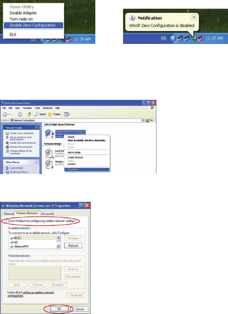
Option 1:
1. Double click the shortcut icon to open the Utility.
2. From the Windows System Tray, you should see the signal icon. Right-click it
and select “Disable Zero-Configuration”.
Option 2:
1. Go to “Control Panel” and double click “Network Connections”.
2. Right-click “Wireless Network Connection” of “WLAN b+g mini-PCI Module”,
and select “Properties”.
3. Select “Wireless Networks” tab, and uncheck the check box of “Use Windows to
configure my wireless network settings”, and then click “OK”.
17
4. Creating an Ad Hoc New Network
NOTE! Ad-hoc mode is available only for 802.11b/g. This is a client product and
do not have radar detection function specified by FCC.
1. In the Configuration window, click New .
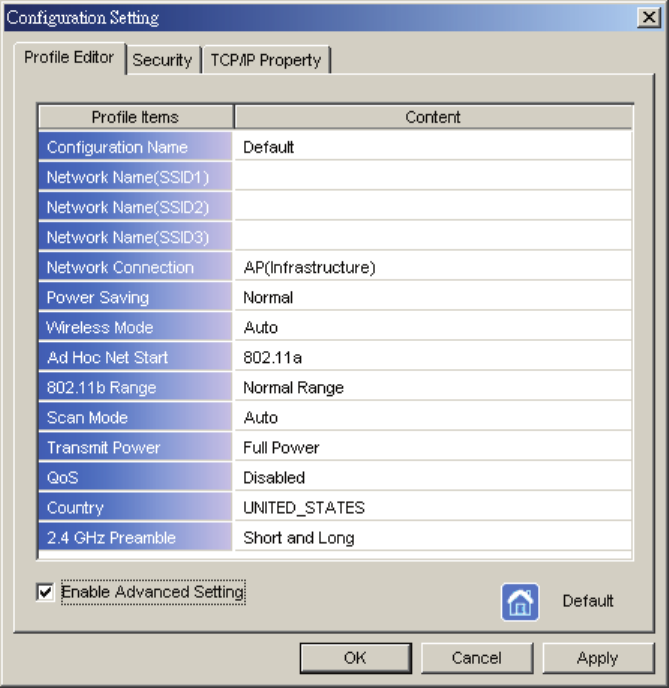
2. Select the “Profile Editor” tab.
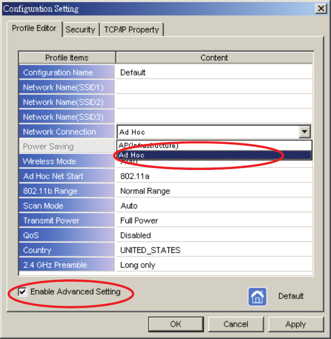
18
3. Choose the check box of Enable Advanced Setting to edit all settings.
4. If joining or creating an Ad-Hoc network, choose Ad Hoc.
5. Click OK (or Apply if using the other tabs) to save the settings.
For details of each setting, refer to Modifying a Wireless Network on page 20.
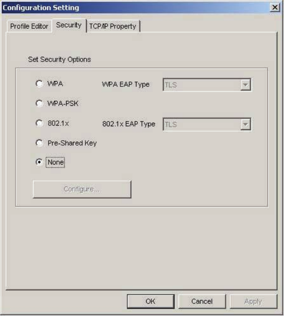
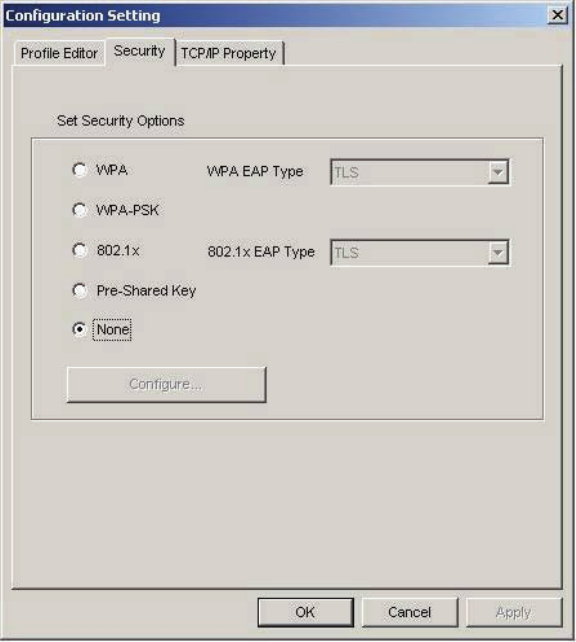
6. Click the Security tab. If not using security, select None.
19
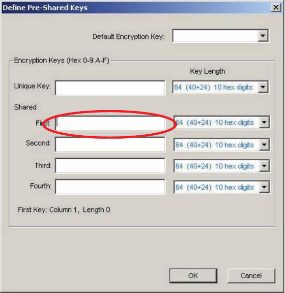
7. If security is used, select Pre-Shared Key and click on the Configure button.
20
8. Enter an encryption key in the Shared: First field.
9. Click OK (or Apply if using the other tabs) to save the settings. The new
Network Name is listed in the Profile List.
The driver does not allow channel selection in Ad-Hoc mode. Instead, the driver
starts with an initial channel then checks channel status. If the channel is busy, the
driver automatically uses a different channel.
For details of each setting, please see chapter 5.
21
5. Modifying a Wireless Network
5.1 Infrastructure Mode and Ad Hoc Mode
You can set the Wireless Network Adapter to work in either Infrastructure mode or
Ad Hoc mode.
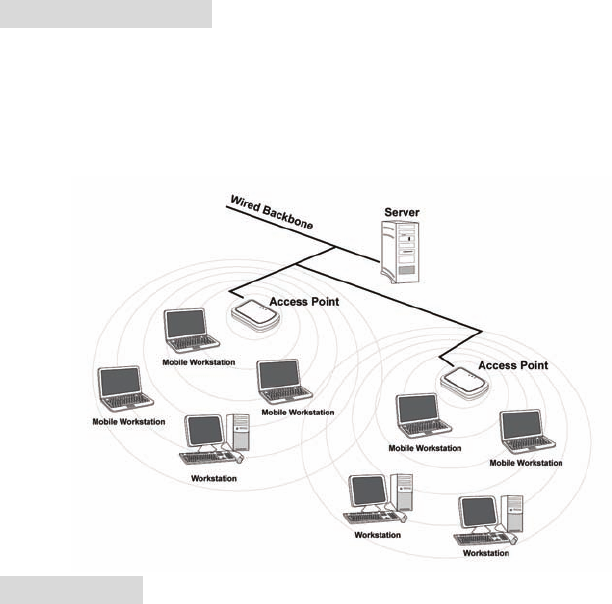
Infrastructure Mode
In infrastructure mode, devices communicate with each other by first going through
an Access Point (AP). Wireless devices can communicate with each other or can
communicate with a wired network. When one AP is connected to wired network
and a set of wireless stations, it is referred to as a BSS (Basic Service Set).
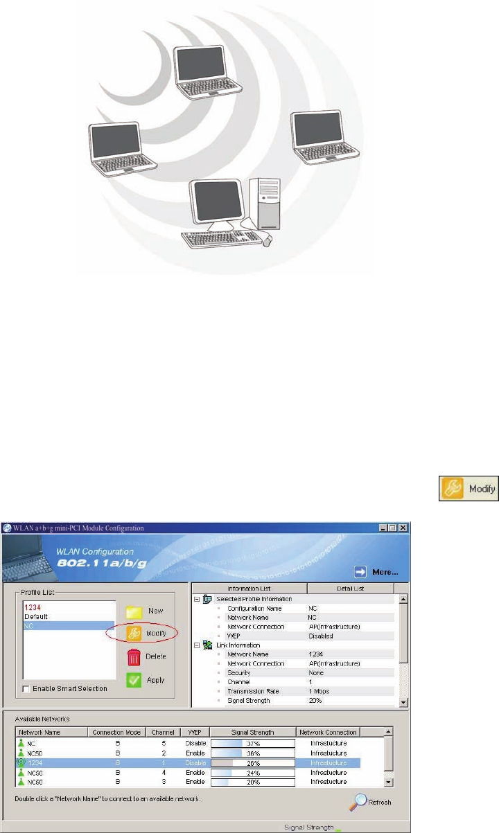
Ad Hoc Mode
Ad-hoc mode is also called “peer-to-peer mode” or “Independent Basic Service Set
(IBSS)”. In ad hoc mode, devices communicate directly with each other without
using an Access Point (AP).
22
5.2 Modifying a Wireless Network
1. Open “WLAN b+g mini-PCI Module Configuration” by double clicking the
shortcut icon on the desktop.
Note! If there’s no network name listed in the “Profile List”, click Refresh
button and double click a Network Name from Available Networks.
The chosen Network Name is listed in the Profile List.
2. From the Profile List, select one Profile and click Modify button .
23
3. Select Profile Editor tab and edit the settings. Click OK to save the
modifications.
Configuration Name: This name identifies the configuration. This name
should be unique.
Network Name (SSID1) (SSID2) (SSID3): The name of the wireless
network. This name cannot be longer than 32 characters. If the field is
set to be “ANY” or is left blank, your computer will connect to an AP with
the best signal strength.
Network Connection: Specifies the mode of the network. Two options
are “Infrastructure” and “Ad Hoc”.
Power Saving: Minimizes power consumption while maintaining network
connectivity and high data transfer performance. In Ad Hoc mode, Power
Savings function cannot be enabled. The power management options are:
• Off: PC Card is powered up at all times.
• Normal: PC Card sleeps less often and stays asleep for a shorter period.
• Maximum: PC Card sleeps more frequently and stays asleep as much as
possible.
Wireless Mode: Three options are “802.11b”, “802.11g”, “Super G” or
24
“Auto”. “Auto” allows the use of either 802.11g or 802.11b mode.
Ad Hoc Net Start: Specifies a band to establish an Ad Hoc network if no
matching SSID is found. Options available are the following: 802.11b and
802.11g.
802.11b Range: Options are Normal Range and Extended Range. This
function can let user to determine the transfer range in 802.11b mode.
Extended Range can prolong the transfer range with a lower data
transmitting rate.
Scan Mode: Options are Active Scan, Passive Scan and Auto. In Active
Scan, the driver sends out the probe request frames from each channel and
collects the response frames from the responding. In Passive Scan, the
driver scan each requested channel, listening the beacons on each channel.
Transmit Power: This setting allows you to change the output power of the
PC Card to increase or decrease the coverage area.
QoS: Disables or enables the PC Card to cooperate in a network using QoS
(Quality of Service).
2.4 GHz Preamble: Allows Ad-Hoc compatibility with other 2.4 GHz
devices. Two options are Short and Long and Long only. Use Long Only
when configuring the client for an 802.11b RoamAbout AP wireless
network.
25
4. Select Security tab and choose the security mode.
Note! Check with your Network Administrator for the security features supported
by your AP.
WPA: Enables the use of WiFi protected Access (WPA). This option
requires IT administration.
a) Select WPA to open the WPA EAP drop-down menu. The options
includes TLS and PEAP.
b) Click on the Configure button and complete the configuration
information in the Define Certificate dialog.
WPA-PSK: Enables the WPA-Pre Shared Key (PSK). Click on the
Configure button and complete the configuration information in the WPA
Passphrase dialog.
802.1x: Enables 802.1x security. This option requires IT administration.
a) Select 802.1x to open the 802.1x EAP drop-down menu. The options
include TLS and PEAP.
b) Click on the Configure button and complete the configuration
information in the Define Certificate dialog.
26
Pre-Shared Key: Enables the use of pre-shared keys that are defined on the
AP and the station.
a) Select the Pre-Shared Key radio button.
b) Click on the Configure button and complete the configuration
information in the Define Certificate dialog.
None: No security.
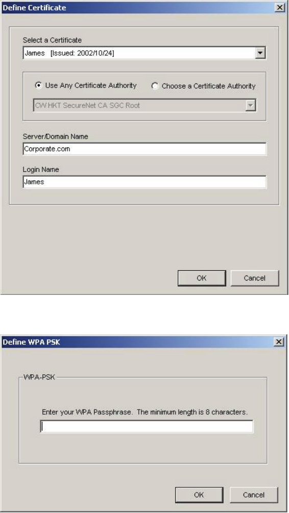
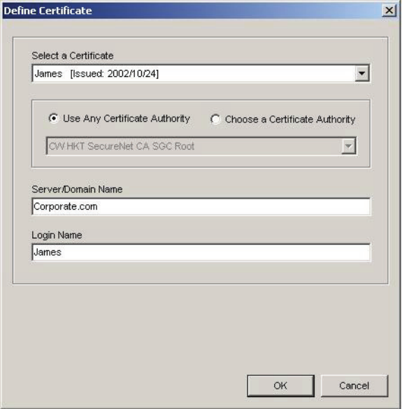
5. Define the Certificate.
Select a Certificate: Select the Certificate to Authenticate to the RADIUS
server from the drop-down menu.
Use any Certificate Authority: The Default Setting. Select this radio
button to use any Certificate Authority (CA) for authentication.
Choose a Certificate Authority: Select this radio button to choose the
desired Certificate Authority for authentication from the drop-down menu.
Server/Domain Name: The the RADIUS server name or the domain name
used for the network access.
Login Name: The username used to log into the server or domain.
Define User Information (PEAP): Click on the Define User Information
button and complete the configuration information in the Define User
Information dialog.
27
6. If selecting WPA-PSK, click on the Configure button to enter the PassPhrase.
The PassPhrase must be a minimum of 8 printable ASCII characters. The
PassPhrase should be at least 20 characters to make it more difficult for an
attacker to decipher the key.
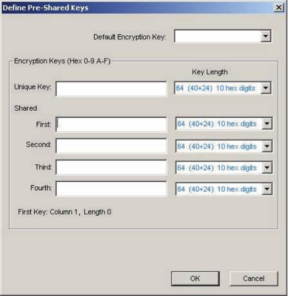
7. If selecting Pre-Shared Key, click on the Configure button to enter the
Encryption Keys.When finished, click OK. For WEP key, please contact with
MIS administrator.
Key Entry Method: Determines the entry method for the key. Hexadecimal
(0-9, A-F) or ASCII text (all keyboard characters).
Default Encryption Key: Allows you to choose one encryption key (First,
Second, Third, or Fourth) as the transmit key, which encrypts transmissions
from the PC Card.
Unique Key: Defines the per-session encryption key for the current network
configuration. Not used in Ad-Hoc mode.
Shared Keys: Use these fields to enter the wireless network’s encryption keys.
The keys must be in the correct position (First, Second, Third, or Fourth).
Key Length: Defines the length of each encryption key.
o For 40/64 bit (enter 10 digits for hexadecimal or 5 characters for ASCII)
o For 104/128 bit (Enter 26 digits for hexadecimal or 13 characters for ASCII)
28
When the length is changed, the number of available characters in the field
automatically changes. If a previously entered key is too long, the key is
automatically truncated to fit. If the key length is increased again, the key does
not update to the previous value.
8. Click OK to save the settings.
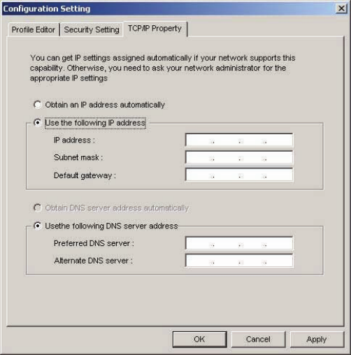
9. Select “TCP/IP Property” tab. Enter the settings and click “OK” to save the
settings.
If the network uses DHCP server, choose Obtain an IP address automatically.
If the network does not use DHCP server, choose Use the following IP address
to set the relative settings. For the IP configuration information, please contact
the network administrator.
29
5.3 Default Settings Windows XP Zero-Configuration
You may also choose the default parameters and directly proceed to Windows XP
zero-configuration through the steps below:
1. Go to “Control Panel” and open “Network Connections”.
2. Right-click the Wireless Network Connection of “WLAN a+b+g mini-PCI
Module”, and make sure this connection is Enabled.
3. Right-click the Wireless Network Connection of “WLAN a+b+g mini-PCI
Module”, and then click “Properties”.
4. Select “Wireless Networks” tab and select “Use Windows to configure my
wireless network settings” check box.
Note! Clear the check box of “Use Windows to configure my wireless network
settings” will disable automatic wireless network configuration.
30
Appendix A: FAQ about WLAN
1. Can I run an application from a remote computer over the wireless network?
This will depend on whether or not the application is designed to be used over a
network. Consult the application’s user guide to determine whether it supports
operation over a network.
2. Can I play computer games with other members of the wireless network?
Yes, as long as the game supports multiple players over a LAN (local area network).
Refer to the game’s user guide for more information.
3. What is Spread Spectrum?
Spread Spectrum technology is a wideband radio frequency technique developed by
the military for use in reliable, secure, mission-critical communications systems. It is
designed to trade off bandwidth efficiency for reliability, integrity, and security. In
other words, more bandwidth is consumed than in the case of narrowband
transmission, but the trade-off produces a signal that is, in effect, louder and thus
easier to detect, provided that the receiver knows the parameters of the
spread-spectrum signal being broadcast. If a receiver is not tuned to the right
frequency, a spread-spectrum signal looks like background noise. There are two main
alternatives, Direct Sequence Spread Spectrum (DSSS) and Frequency Hopping
Spread Spectrum (FHSS).
4. What is DSSS? What is FHSS? And what are their differences?
Frequency-Hopping Spread-Spectrum (FHSS) uses a narrowband carrier that changes
frequency in a pattern that is known to both transmitter and receiver. Properly
synchronized, the net effect is to maintain a single logical channel. To an unintended
receiver, FHSS appears to be short-duration impulse noise. Direct-Sequence
Spread-Spectrum (DSSS) generates a redundant bit pattern for each bit to be
transmitted. This bit pattern is called a chip (or chipping code). The longer the chip,
the greater the probability that the original data can be recovered. Even if one or more
bits in the chip are damaged during transmission, statistical techniques embedded in
the radio can recover the original data without the need for retransmission. To an
unintended receiver, DSSS appears as low power wideband noise and is rejected
(ignored) by most narrowband receivers.
31
5. Would the information be intercepted while transmitting on air?
WLAN features two-fold protection in security. On the hardware side, as with Direct
Sequence Spread Spectrum technology, it has the inherent security feature of
scrambling. On the software side, WLAN offers the encryption function (WEP) to
enhance security and access control.
6. What is WEP?
WEP is Wired Equivalent Privacy, a data privacy mechanism based on a 64-bit or
128-bit shared key algorithm, as described in the IEEE 802.11 standard.
7. What is infrastructure mode?
When a wireless network is set to infrastructure mode, the wireless network is
configured to communicate with a wired network through a wireless access point.
8. What is roaming?
Roaming is the ability of a portable computer user to communicate continuously
while moving freely throughout an area greater than that covered by a single access
point. Before using the roaming function, the workstation must make sure that it is the
same channel number with the access point of dedicated coverage area.
To achieve true seamless connectivity, the wireless LAN must incorporate a number
of different functions. Each node and access point, for example, must always
acknowledge receipt of each message. Each node must maintain contact with the
wireless network even when not actually transmitting data. Achieving these functions
simultaneously requires a dynamic RF networking technology that links access points
and nodes. In such a system, the user’s end node undertakes a search for the best
possible access to the system. First, it evaluates such factors as signal strength and
quality, as well as the message load currently being carried by each access point and
the distance of each access point to the wired backbone. Based on that information,
the node next selects the right access point and registers its address. Communications
between end node and host computer can then be transmitted up and down the
backbone. As the user moves on, the end node’s RF transmitter regularly checks the
system to determine whether it is in touch with the original access point or whether it
should seek a new one. When a node no longer receives acknowledgment from its
original access point, it undertakes a new search. Upon finding a new access point, it
then re-registers, and the communication process continues.

32
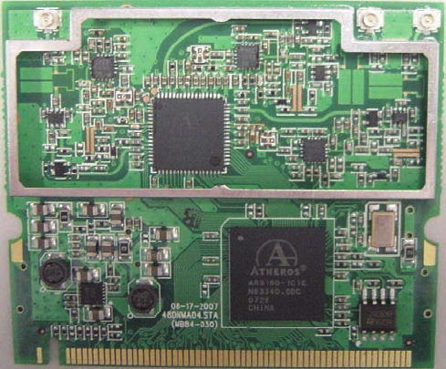
Appendix B: Specification
DNMA-84, Product Specification, 802.11n draft 2.0 b/g mini-PCI card
Item Key specifications
Main chipset Atheros® AR9160, AR9103
TX/RX 3T3R
Frequency
range
USA: 2.400 – 2.4836GHz
Europe: 2.400 – 2.4836GHz
Japan: 2.400 – 2.497GHz
China: 2.400 – 2.4836GHz
Modulation
technique
DSSS (Direct Sequence Spread Spectrum) with
DBPSK (Differential Binary Phase Shift Keying 1Mbps),
DQPSK (Differential Quaternary Phase Shift Keying 2Mbps), and
CCK (Complementary Code Keying 5.5&11Mbps), and
OFDM (Orthogonal Frequency Division Multiplexing with BPSK for 6,9Mbps、 QPSK for
12,18Mbps、 16QAM for 24,36Mbps、 64QAM for 48,54Mbps)
802.11n b/g
DSSS (DBPSK, DQPSK, CCK)
OFDM (BPSK, QPSK, 16-QAM, 64-QAM)
Host interface Mini-PCI form factor; Mini-PCI Version 1.0 type ШA
Channel
spacing
5MHz
Channels
support
802.11n b/g
US/Canada: 11 (1 ~ 11)
Major European country: 13 (1 ~ 13)
France: 4 (10 ~ 13)
Japan: 11b: 14 (1~13 or 14th), 11g: 13 (1 ~ 13)
China: 13 (1 ~ 13)
Operation
voltage
3.3V +/-5%
Power
consumption
@25 o C
802.11b 802.11g 802.11n(Ng HT20)
802.11n(Ng HT40)
Avg/Peak (mA) Avg/Peak (mA) Avg/Peak (mA) Avg/Peak
(mA)
Continue Tx 1207/1356 1184/1357 1284/1471

33
1373/1587
FTP Tx TBD TBD TBD
TBD
FTP Rx TBD TBD TBD
TBD
Standby mode TBD 349/418 TBD
TBD
Power savin
g
TBD TBD TBD
TBD
***The maximum current consumption would be impacted by radiation environment and the
driver mechanism.
*** Due to without NDIS driver supporting from Atheros for Windows OS, so the detail current
consumption was hard to be gotten at this moment.
Output power
@25 o C
802.11b
Test Frequencies 1/2_Target 5.5_Target 11_Target
2412 19 19
19
2437 19 19
19
2462 19 19
19
2472 19 19
19
802.11g
Test Frequencies 6-36_Target 48_Target 54_Target
2412 19 17
16
2437 19 17
16
2462 19 17
16
2472 19 17
16
802.11n
Freq. Range: 2.4GHz/HT20: @800GI(400GI)
Test Freq MCS 0/8 MCS 1/9 MCS 2/10 MCS 3/11 MCS 4/12 MCS 5/13 MCS 6/14

34
MCS 7/15
M
bps (800ns) 6.5/13 13/26 19.5/39 26/52 39/78
52/104 58.5/117 65/130
2412 19 19 19 19
18 17 16 13
2437 19 19 19 19
18 17 16 13
2462 19 19 19 19
18 17 16 13
2472 19 19 19 19
18 17 16 13
Freq. Range: 2.4GHz/HT40: @800GI(400GI)
Test Freq MCS 0/8 MCS 1/9 MCS 2/10 MCS 3/11 MCS 4/12 MCS 5/13 MCS 6/14
MCS 7/15
M
bps (800ns) 13.5/27 27/54 40.5/81 54/108 81/162 108/216
121.5/243 135/270
2412 19 19 19 19
18 16 15 12
2437 19 19 19 19
18 16 15 12
2462 19 19 19 19
18 16 15 12
2472 19 19 19 19
18 16 15 12
EVM
@25 o C
The transmit modulation accuracy is measured using error vector magnitude (EVM).
EVM is the magnitude of the phase difference as a function of time between an ideal
reference signal and the measured transmitted signal.
802.11b
Modulation Code Rate Relative constellation error (dB) Relative constellation
error (dB)
IEEE Spec (1Tx dB) Typical/Maximum
(3Tx dB)
DBPSK (1 Mbps) -10
-19/-16
DQPSK (2 Mbps) -10

35
-19/-16
CCK (5.5 &11 Mbps) -10
-19/-16
802.11g
Modulation Code Rate Relative constellation error (dB) Relative constellation
error (dB)
IEEE Spec (1Tx dB) Typical/Maximum
(3Tx dB)
BPSK (6 Mbps) 1/2 -5
-27/-24
BPSK (9 Mbps) 3/4 -8
-27/-24
QPSK (12 Mbps) 1/2 -10
-27/-24
QPSK (18 Mbps) 3/4 -13
-27/-24
16-QAM (24 Mbps) 1/2 -16
-27/-24
16-QAM (36 Mbps) 3/4 -19
-30/-27
64-QAM (48 Mbps) 2/3 -22
-31/-28
64-QAM (54 Mbps) 3/4 -25
-31/-28
802.11ng
Modulation Code Rate Relative constellation error (dB) Relative constellation
error (dB)
IEEE Spec (1Tx dB) Typical/Maximum
(3Tx dB)
o HT20
(MCS0) BPSK 1/2 -5
-29/-26
(MCS1) QPSK 1/2 -10
-29/-26
(MCS2) QPSK 3/4 -13
-30/-27

36
(MCS3) 16-QAM 1/2 -16
-30/-27
(MCS4) 16-QAM 3/4 -19
-31/-28
(MCS5) 64-QAM 2/3 -22
-32/-29
(MCS6) 64-QAM 3/4 -25
-32/-29
(MCS7) 64-QAM 5/6 -28
-33/-30
(MCS8) BPSK 1/2 -5
-26/-23
(MCS9) QPSK 1/2 -10
-26/-23
(MCS10) QPSK 3/4 -13
-26/-23
(MCS11) 16-QAM 1/2 -16
-26/-23
(MCS12) 16-QAM 3/4 -19
-29/-26
(MCS13) 64-QAM 2/3 -22
-30/-27
(MCS14) 64-QAM 3/4 -25
-30/-27
(MCS15) 64-QAM 5/6 -28
-32/-29
o HT40
(MCS0) BPSK 1/2 -5
-29/-26
(MCS1) QPSK 1/2 -10
-29/-26
(MCS2) QPSK 3/4 -13
-29/-26
(MCS3) 16-QAM 1/2 -16
-29/-26

37
(MCS4) 16-QAM 3/4 -19
-30/-27
(MCS5) 64-QAM 2/3 -22
-31/-28
(MCS6) 64-QAM 3/4 -25
-32/-29
(MCS7) 64-QAM 5/6 -28
-33/-30
(MCS8) BPSK 1/2 -5
-24/-21
(MCS9) QPSK 1/2 -10
-24/-21
(MCS10) QPSK 3/4 -13
-24/-21
(MCS11) 16-QAM 1/2 -16
-24/-21
(MCS12) 16-QAM 3/4 -19
-27/-24
(MCS13) 64-QAM 2/3 -22
-28/-25
(MCS14) 64-QAM 3/4 -25
-29/-26
(MCS15) 64-QAM 5/6 -28
-30/-28

38
Sensitivity
@25 o C
802.11b
Modulation IEEE Spec (1Rx dBm)
Typical/Maximum (3Rx dBm)
DBPSK -82
-95/-92
DQPSK -80
-93/-90
CCK -76
-91/-88
802.11g
Modulation Code Rate IEEE Spec (1Rx dBm)
Typical/Maximum (3Rx dBm)
BPSK 1/2 -82
-95/-92
BPSK 3/4 -81
-95/-92
QPSK 1/2 -79
-95/-92
QPSK 3/4 -77
-95/-92
16-QAM 1/2 -74
-91/-88
16-QAM 3/4 -70
-88/-85
64-QAM 2/3 -66
-84/-81
64-QAM 3/4 -65
-82/-79
802.11ng
Modulation Code Rate IEEE Spec (1Rx dBm)
Typical/Maximum (3Rx dBm)
o HT20
(MCS0) BPSK 1/2 -82
-95/-92
(MCS1) QPSK 1/2 -79
-94/-91

39
(MCS2) QPSK 3/4 -77
-92/-89
(MCS3) 16-QAM 1/2 -74
-89/-86
(MCS4) 16-QAM 3/4 -70
-86/-83
(MCS5) 64-QAM 2/3 -66
-82/-79
(MCS6) 64-QAM 3/4 -65
-80/-77
(MCS7) 64-QAM 5/6 -64
-78/-75
(MCS8) BPSK 1/2 -82
-94/-90
(MCS9) QPSK 1/2 -79
-92/-89
(MCS10) QPSK 3/4 -77
-90/-87
(MCS11) 16-QAM 1/2 -74
-87/-84
(MCS12) 16-QAM 3/4 -70
-84/-81
(MCS13) 64-QAM 2/3 -66
-79/-75
(MCS14) 64-QAM 3/4 -65
-78/-75
(MCS15) 64-QAM 5/6 -64
-76/-73
o HT40
(MCS0) BPSK 1/2 -79
-89/-86
(MCS1) QPSK 1/2 -76
-89/-86
(MCS2) QPSK 3/4 -74
-89/-86
(MCS3) 16-QAM 1/2 -71
86/
8
3

40
-86/-83
(MCS4) 16-QAM 3/4 -67
-83/-80
(MCS5) 64-QAM 2/3 -63
-78/-75
(MCS6) 64-QAM 3/4 -62
-77/-74
(MCS7) 64-QAM 5/6 -61
-75/-72
(MCS8) BPSK 1/2 -79
-89/-86
(MCS9) QPSK 1/2 -76
-88/-84
(MCS10) QPSK 3/4 -74
-86/-83
(MCS11) 16-QAM 1/2 -71
-83/-80
(MCS12) 16-QAM 3/4 -67
-80/-77
(MCS13) 64-QAM 2/3 -63
-75/-71
(MCS14) 64-QAM 3/4 -62
-73/-69
(MCS15) 64-QAM 5/6 -61
-72/-68

41
Operation
distance
802.11b
Outdoor: 150 m @11Mbps, 300 m @1Mbps
Indoor: 30 m @11Mbps, 100 m @1Mbps
802.11g
Outdoor: 50 m @54Mbps, 300 m @6Mbps
Indoor: 30 m @54Mbps, 100 m @6Mbps
802.11n
Outdoor: 250 m @6.5Mbps (MCS0: 1 Nss/20MHz BW)
30 m @130Mbps (MCS15: 2 Nss/20MHz BW)
30 m @300Mbps (MCS15: 2 Nss/40MHz BW)
Indoor: 100 m @6.5Mbps (MCS0: 1 Nss/20MHz BW)
20 m @130Mbps (MCS15: 2 Nss/20MHz BW)
20 m @300Mbps (MCS15: 2 Nss/40MHz BW)
Transmit
spectrum
mask
For transmitted spectral mask for 11b shall be less than –50dBr for fc–22MHz<f<fc+22MHz.
For transmitted spectral mask for 11g shall be less than –40dBr for fc–30MHz<f<fc+30MHz.
For transmitted spectral mask for 11n 20MHz shall be less than –45dBr for
fc–30MHz<f<fc+30MHz.
For transmitted spectral mask for 11n 40MHz shall be less than –45dBr for
fc–60MHz<f<fc+60MHz.
Mode of Operation
80 802.11g
IEEE Specifications
802.11g at 9 MHz Offset 0 dBr
802.11g at 11 MHz Offset -20 dBr
802.11g at 20 MHz Offset -28 dBr
802.11g at 30 MHz Offset -40 dBr
Mode of Operation
802.11b
IEEE Specifications
802.11b at 11 MHz Offset -30dBr
802.11b at 22 MHz Offset -50dBr
Mode of Operation
802.11n
IEEE Specifications
802.11n at 19 MHz offset 0 dBr
802.11n at 21 MHz offset -20 dBr
802.11n at 40 MHz offset -28 dBr
802.11n at 60 MHz offset -45 dBr
Transmit
spectrum
flatness
For 802.11g the average energy of the constellations in each of spectral lines –16..-1
and +1..+16 will deviate no more than +/- 2dB from their average energy.
For 802.11n 40MHz mode, the average energy of the constellations in each of spectral

42
lines –42..-2 and +2..+42 will deviate no more than +/- 2dB from their average energy.
The transmitted spectral flatness should be with in +2/- 4dB.
Transmit
center
frequency
tolerance
The transmitted center frequency tolerance shall be ±20 ppm maximum.
Carrier
suppression
802.11b:
The RF carrier suppression, measured at the channel center frequency, shall be at least
15 dB below the peak SIN(x)/x power spectrum.
802.11g:
The leakage of the center frequency component shall not exceed -15 dB relative to
overall transmitted power or, equivalently, +2 dB relative to the average energy of the
rest of the sub-carriers.
802.11n:
For all 20 MHz modes of transmission
The leakage of the center frequency component shall not exceed -15 dB relative to
overall transmitted power or, equivalently, +2 dB relative to the average energy of the
rest of the sub-carriers.
For all 40 MHz modes of transmission
The center frequency leakage shall not exceed -18 dB relative to overall transmitted
power, or, equivalently, +2 dB relative to the average energy of the rest of the
sub-carriers.
Delta > 15dB for b, g & 11n 20MHz
Delta > 18dB for 11n 40MHz
Transmit
power on
ramp and
power down
ramp time
The transmitting power-on ramp for 10% to 90% of maximum power m shall be no greater
than 2 µs.
The transmitting power-down ramp for 90% to 10% of maximum power shall be no greater
than 2 µs.
Receiver
maximum
input level
802.11b
Modulation IEEE Spec (1Rx dBm)
DBPSK >-4
DQPSK >-4
CCK >-10

43
802.11g
Modulation Code Rate IEEE Spec (1Rx dBm)
>-20
802.11ng
Modulation Code Rate IEEE Spec (1Rx dBm)
>-20
Operation
system
supported
Linux (TBD), without Windows OS supported
PCB
dimension
50.8mm ±0.1 Max (L/H) x 59.6mm ±0.1 (W) x 1.0mm ±0.1 (T)
Security
64-bit, 128-bit, 152-bit WEP Encryption
802.1x Authentication
AES-CCM & TKIP Encryption
Operation
mode
Infrastructure
Transfer data
rate
802.11b: 1, 2, 5.5, 11Mbps
802.11g: 6, 9, 12, 18, 24, 36, 48, 54Mbps
802.11n: @800GI(400GI)
20MHz BW
1 Nss: 65(72.2) Mbps maximal
2 Nss: 130(144.444) Mbps maximal
40MHz BW
1 Nss: 135(150) Mbps maximal
2 Nss: 270(300) Mbps maximal
Operation
temperature
0o ~ 60o C
Storage
temperature
-20o ~ 80o C
Wi-Fi
alliance
WECA Compliant
WHQL No, due to without NDIS driver supported
EMC
certificate
FCC part 15 (USA)
IC RSS210 (Canada)
TELEC (Japan)
ETSI, EN301893, EN60950 (Europe)
VCCI CLASS B

44
Media access
protocol
CSMA/CA with ACK architecture 32-bit MAC
Antenna 3 x SMT Ultra-miniature coaxial connectors