Wistron NeWeb DNXA116 2X2 802.11n PCIe module User Manual AR5BHB116 2010 8 23
Wistron NeWeb Corporation 2X2 802.11n PCIe module AR5BHB116 2010 8 23
User Manual

WNC 802.11n
Adapter
Model DNXA-116
802.11n Adapter

Notice
0023
42Wistron NeWeb Corporation5WNC6
10/
1/1001.0
1WNC/10
11111WNC11
001001
310110
011717102WNC
WNC0011111/1
/2/11110
7131717102
WNC
WNC,8"%3$+##3 "%$3983*+ !#"-#* $ !"$3 "3 $ !%
*$(,"3 33$":"3 %!;;WNC<";<;"$#*#" 3*#" %)";
3*"3 ;%)"(; $#9$#$3%"=("3 ;*,-"%#%3-#$, !"(%"$#
3<; 9 $(%" !%)#$*( $#*$(,"3 $3":"3*:%"*$ !")$%%<; 9
$%(!*,-"%3)# (;#WNC%!;;3$ !:";<; 9$#39
!#*+#"%$ +#"$#* #3%, "*$#$ !"#+%"(%"*+ ! !")#$*(
3;(*3- !"$% %$#")#3-#");3-3 "-# 3-3% ;;3-$#
#"$:"#3-%(!!#*+#"%$ +#"$#* WNC%)";;9*%;,%
!",);"*+##3 "%$,"#!3 <; 93* 3"%%$#)# (;#)(#)$%"
% !"9,-! $ !"#+%"));9 $ !%*$(,"3 3* $ !"*"%, "#;3*
3$#, $3">)#"%%"*!"#"3

• iii
Document Conventions
Text Conventions
<121170
11
"71? *8@1/20
0
+
10
"71?
01
Courier 011
"71?
Error:Unable to allocate memory for transfer!
Menu ,0
"71?EditACopy
BC +D/1
110
EF +10
2
G +11
H 11011
A /1
"71?StartAProgramsADKAwdreg_install
Notices
NOTE: This message denotes neutral or positive information that calls out
important points to the text. A note provides information that may apply only
in special cases.

iv •
Revision History
Revision Description of Changes
I #

• v
Contents
J
%#D J
)0, J
,00)0 J
#0)0 K
)0%, K
%2*000)0
1"71)0
1)0
"71)0
)L)0
0 )L)02/?
- I
I
% II
(")' ;%% I
(")' ;%% I
()")5")'- 6% IM
()")',%!):% IN
(;")% I&
0;") I&
)'%"18 I
*01'1/? I
$2"7%+")8 I
*%+") I
(+))1% IJ
O0 IJ
+32/0 IJ
/%0* IK

vi •
%IK
10<I
* I
#
%32/
002/
*1%
(
M
N
= N
#%%PN
!,N
!,)00 N
05)6,&
05)6,)00&
($*
%
,/5,6
%0J
1K
3? 錯誤
錯誤錯誤
錯誤尚未定義書籤
尚未定義書籤尚未定義書籤
尚未定義書籤。
。。
。
0QR#QS?錯誤
錯誤錯誤
錯誤尚未定義
尚未定義尚未定義
尚未定義
書籤
書籤書籤
書籤。
。。
。
"1T"3? K

• 7
Introduction
WNCKII111KII1 WNC
(5(62'100
WNC2/01
System Requirements
;11L)?
M')"71<
M,<
M,!.1
,0+2+2,"+2K%
"+2>)+23 N52%)/6
Profile Management
022/15260)0,
0WNC(
10
"10
1)0
"71)0
$10
%20010
#10
*00
32/
22/12/052
16510112;36
Create or Modify a Configuration Profile
2010/32)0, 0
01000)0/,0
)0,71-10?
"-
"%
"
0100150632/
10
3(20I0100
0I10/321#
10071002
Microsoft Windows 2000, Windows Millennium Edition, Windows 98 Second Edition,
Windows XP, or Windows NT 4.0 (with Service Pack 6)
Configure the wireless network adapter (wireless card) from the Profile Management tab of the
WNC Client Utility.
Add a profile
Edit a profile
Import a Profile
Export a Profile
Order profiles
Switch to a different profile
Remove a profile
Connect to a Different Network
The wireless network adapter works in either infrastructure mode (which uses an access point) or
ad hoc mode (a group of stations participating in the wireless LAN).
Create or Modify a Configuration Profile
To add a new configuration profile, click New on the Profile Management tab. To modify a
configuration profile, select the configuration from the Profile list and click the Modify button.

8 •
Remove a Configuration Profile
I -)0,
%1000010
M /#
Auto Profile Selection Management
100221
100010
2/
Including a profile in auto profile selection:
I $)0,/$)0
)0%,221120
10)07
M !1010/ 10
11%)07
Ordering the auto selected profiles:
I !10%)07
/,(1,*2#111 010
%)0711021
M /$8
N /%)07
& %000
+10/%)0)0
,102/ 102
1%%*002/
2/0017
110%%*
+102102/
1102%%*02/
2/$01271
10

• 9
Feb. 2009
Switching to a Different Configuration Profile
I 20010)0,
/10)0;
M /
)0;1101010
110010
Import and Export Profiles
Importing a Profile
I )0,/1 1)0
2211
<2210
M !10
N /$1 1101110
Exporting a Profile
I )0,1071
/"71 "71)02211
M <27110
N /% 107110
TCP/IP Configuration
Configuring the TCP/IP Address for the network device:
I 0022/1111)
132/*'1
;222/1#'
//)1
M %)5 )L)6/)1
N /(02))%
/)%/21
1506*0
2*3%0D)00
5*!))2*3%)6
01 00
& /$80
1. From the Profile Management tab, click the Import button. The Import Profile window appears.
2. Browse to the directory where the profile is located.
3.Highlight the profile name.
4. Click Open. The imported profile appears in the profiles list.
1. From the Profile Management tab, highlight the profile to export.
2. Click the Export button. The Export Profile window appears.
3. Browse to the directory to export the profile to.
4. Click Save. The profile is exported to the specified location.
TPC/IC Configration
Configuring the TPC/IC Address for the network device:
1. After configuring the wireless network adapter properties, open the Control Panel and open Network and Dial-up
Connections.
2. Find the Local Area Connection associated with the wireless network adapter. Right-click that connection, and click
Properties.
3. Select Internet Protocol (TCP/IP) and click Properties. 4. Click the radio button Use the following IP address, then
enter an IP address and Subnet mask. Assigning an IP address and Subnet mask allows stations to operate in access
point mode (infrastructure mode) or in ad hoc mode and to have Internet access. Default gateway and DNS server
information is also required. IP configuration information (DHCP to assign the IP address, gateway and DNS server IP
addresses) is usually obtained from the corporate IT staff.
5. Click OK to finish.
10 •
General Tab
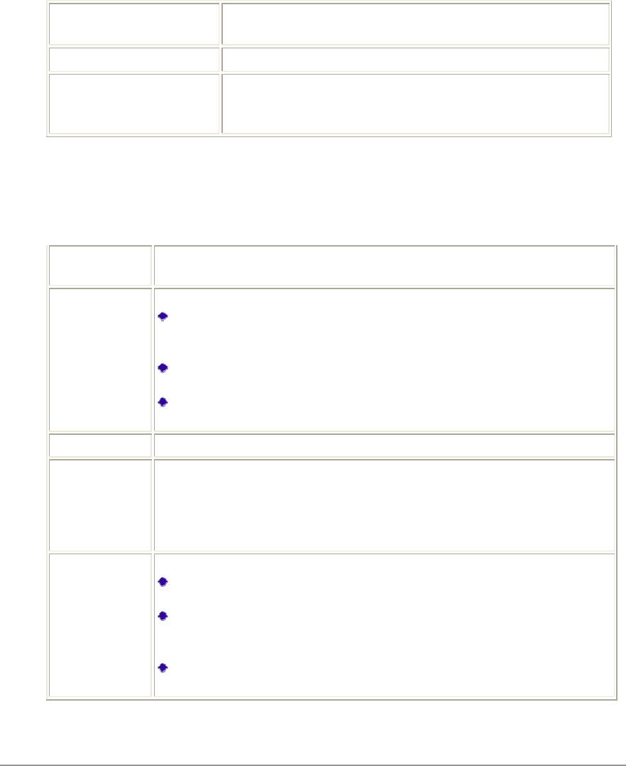
WNC(-/32,0
)0,"0-00
10,/%
Profile Name 0010
D)0
Client Name 0
Network Names (SSIDs) """KII22/ 0
70M
01%%*5%%*I%%*%%*M6
Advanced Tab
WNC(/32,0
)0,/)0,"
00)0,010
Transmit
Power Level
%12+12
2
Power Save
Mode %10?
,7100
021 111
102
37201/
2/1201/
$00120012121
01
Network Type %102/0
802.11b
Preamble %101KII 0%U
;51622
KII0 10
111%;$
20
Authentication
Mode %21)?
11
2100
$1110
+")2210+")
/11
%2121
+")/
In the WNC Client Utility, access the Advanced tab by clicking New or Modify on the Profile
Management tab, then clicking the Advanced tab in Profile Management. Edit the fields in the
Advanced tab of Profile Management to configure the profile.
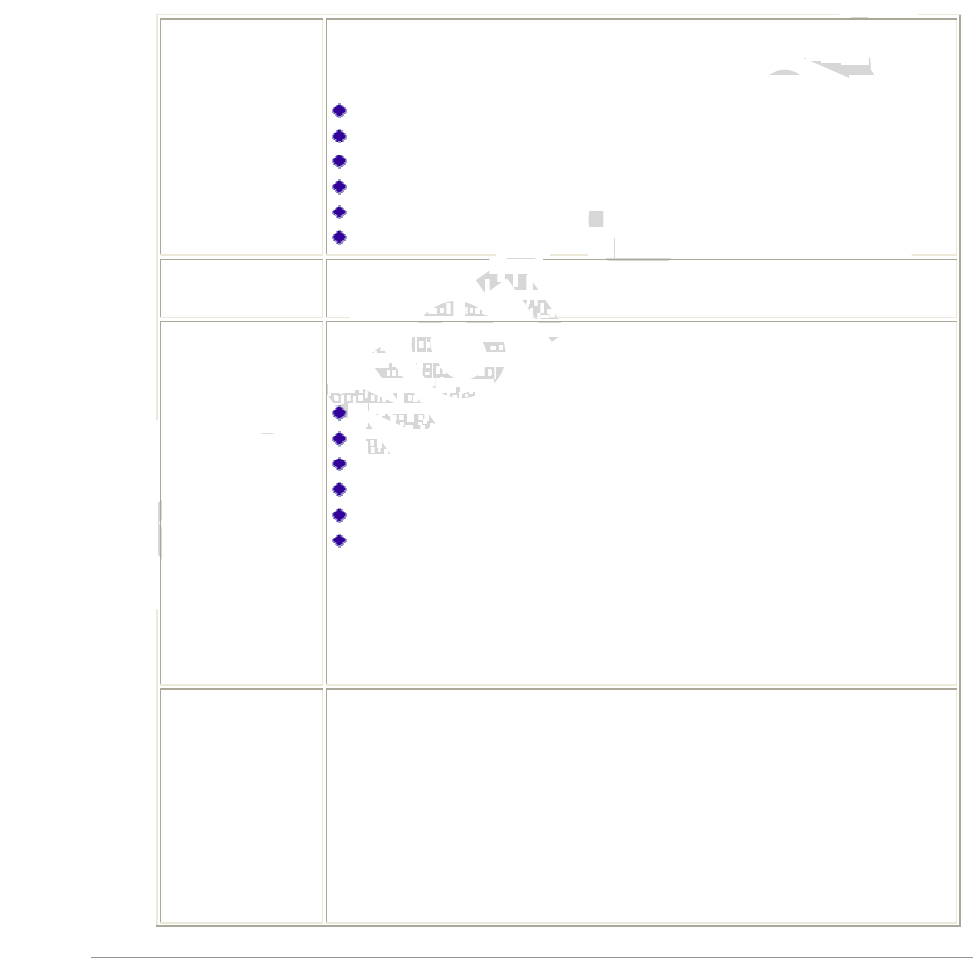
• 11
05162//)0)101
01211
Security Tab
WNC(%/32,0
)0,/%)0,22
"0%0)0,010
00,/
-
WPA/WPA2 "0+')5+)6
+)L+)1+)L+)")1'2
1?
")'%
")' ;%
")' ;%
)")5")'- 6
)")5")',%!):6
;")
WPA/WPA2
Passphrase "+)L+))1/0
0+)L+))1
802.1x "KI7 1D
KI71KI7")11'2
1?
")'%
")' ;%
")' ;%
)")5")'- 6
)")5")',%!):6
;")
0121
+")$1+")/
2,7/%
2Note:0;//7/
10%
Pre-Shared Key
(Static WEP) "01'/0
1
01'1/)'%8
/00*0)'
%822
0121
+")$1+")/
2,7/%

12 •
2
None 356
Using EAP-TLS Security
")' ;%WNC(%
)0,22
I $%+)
$#?$%KI7
")' ;%01'2
Enabling EAP-TLS security:
")' ;%")' ;%0
2/2
I 0")' ;%11")' ;%01'2
/0
%11100 L
0000/
$8
M /$8
N 10
Using EAP-TTLS Security
")WNC(%)0
,22
I $%+)L+)
$#?$%KI7
")' ;%01'2
Enabling EAP-TTLS security:
")' ;%")' ;%0
2/2
I 0")' ;%11")' ;%01'2
/0
%111001'2/$8
M %100")?
/(+2(3+2")
$#?"")(301
12")1
N /?
;0/0100
2032/0
1'2

• 13
"00221
0
0
& /$8
"10
Using PEAP (EAP-GTC) Security
)")5")'- 6WNC(%
)0,22
I $%+)
$#?$%KI7
)")5")'- 601'2
+)')")0
11/2
I /0
0150710
16/2#%
%
M %1112/001'2
N %100)")?
/(+2(3+2)")
$#?")")(301
)")1
& /%)21
3 /2/%1%0 /
15IM6'12
/%?
;0/0100
2032/0
1'2
"00221
0
0)")0
)")'21V,
0
J /$8
K "10
To use PEAP (EAP-GTC) security, the server must have WPA-PEAP certificates, and
the server properties must already be set. Check with the IT manager.
1. Click the Configure button.
2. To avoid the need to log on again after resuming operation (for example, after your
computer goes into standby or hibernate mode), check Always Resume the Secure
Session.
3. Select the appropriate network certificate authority from the drop-down list.
4. Specify a user name for inner PEAP tunnel authentication: Check Use Windows
User Name to use the Windows user name as the PEAP user name. OR: Enter a PEAP
user name in the User Name field to use a separate user name and start the PEAP
authentication process.
5. Choose Token or Static Password, depending on the user database. Note that Token
uses a hardware token device or the Secure Computing SofToken program (version 1.3
or later) to obtain and enter a one-time password during authentication.
6. Click Settings... and:
Leave the server name field blank for the client to accept a certificate from any server
with a certificate signed by the authority listed in the Network Certificate Authority
drop-down list. (recommended)
Enter the domain name of the server from which the client will accept a certificate.
The login name used for PEAP tunnel authentication fills in automatically as
PEAP-xxxxxxxxxxxx, where xxxxxxxxxxxx is the computer's MAC address. Change
the login name if needed.
7. Click OK.
8. Enable the profile.

14 •
Using PEAP-MSCHAP V2 Security
)")',%!):WNC(%
)0,22
I $%+)
$#?$%KI7
)")5")',%!):601'2
!"+)')")0
11/2
I /0
%111001'2
M %100)")?
/(+2(3+2)")
$#?")")(301
)")1
N /?
;0/0100
2032/0
1'2
"00221
0
0)")0
)")'21V,
0
& /$8
"10

• 15
Using LEAP Security
WNC(%)0
,22;")D05
1600;")/2
Configuring LEAP
$%+)+)';")0
1'2
$#?$%KI7;")0
1'2
I /0
%1012%( 1(3
)2?
/(+2(3+2;")
$#?/,)10;")(3)2
;")1
%(%(3)2?
%10;")12
M "12
N 012
& %10?
/+2;*2(31
+2#*(%#
$#?"10
0/332/((;0
21000
J ";")52M&6
102;")200
0
K /$8
"10
1. Click the Configure button.
2. Specify a user name and password. Select to Use Temporary User Name and Password by choosing
the radio button:
Select to Use Saved User Name and Password by choosing the radio button:
Specify the LEAP user name, password, and domail to save and use.
3. Enter the user name and password.
4. Confirm the password.
5. Specify a domain name:
Check the Include Windows Logon Domain with User Name setting to pass the Windows login
domain and user name to the RADIUS server. (default)
OR: Enter a specific domain name.
16 •
Pre-Shared Encryption Keys
Defining pre-shared encryption keys:
I /)'%85%+")6%
/0
M 0*0)'%87?
Key Entry *01/?75'
'6%75/7116
Encryption
Keys %01/$20
% /21
01
WEP Keys
(1-4) *001/02/0
%8011
/
//01/
WEP Key
Size *0.01/ 1?
N'5I07&%6
IK'507IM0%6
I&'5M7I0%6
N /$80/00
Overwriting an Existing Static WEP Key
I /)'%8%
/0
M 227+")/1/0
/007+")/2
N */0
& "2/
,/ 800/0
/1/
J /$8
Disabling Static WEP
+")0110%1
)0,+")
$#?3%/$85
6

• 17
Using WPA Passphrase Security
+))1WNC(%
)0,22
I $%+))1
/0
M +))1
N /$8
Zero Configuration
10WNC(5(6+2
>)+0%5+O%6
Wireless Network Configuration
+2+O%2
2$000
O0+2>)/021?
I +2>)1+32/0)17
%/7W(+2022/X
O0
+/7+2>)/00
010?
%%*
%/
!
O00102
1!2(022O
0?
)2
L)52116
12
+
%L;15KII6
+O011'11(2
10100)0,0
(
This section describes the operation of the WNC Client Utility (ACU) and Windows XP Wireless Configuration
Service (WZCS).
This section describes the operation of the WNC Client Utility (ACU) and Windows XP Wireless Configuration
Service (WZCS). Wireless Network Configuration The Windows WZCS is a service that manages the wireless
connection in a largely dynamic way. Only minimal connection information must be identified and configured.
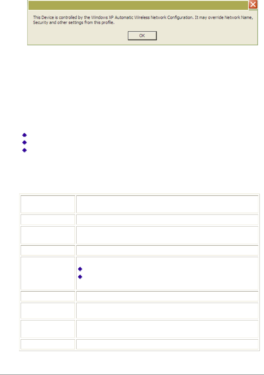
To set Zero Configuration on Windows XP, take the following steps:
1. In Windows XP, open the Wireless Network Configuration Properties dialog box.
2. Select the check box “Use Windows to configure my wireless network settings” to set Zero Configuration.
When this check box is selected, Windows XP takes control of these settings for all configuration profiles:
SSID
Security keys
Ad hoc settings
Note that Windows XP takes control of these settings for all configuration profiles, thus users can not ( create
new profiles with different settings while using Windows Zero Configuration.
18 •
O000+2>)/021?
I +2>)1+32/0)17
/7W(+2022/X
O0+/710
010210()0,
Check the Status Information or Diagnostics
WNC01
0
/
/0
/
Current Status
%01
1 %D0 02
0%
Profile Name 0010%1
0-
Link Status %2222/
Wireless Mode *1202
IP Address *11V)
Network Type 102/$1?
0516
!
02/1
Current Channel %2
Server Based
Authentication %22
Data Encryption *1110
11%
Signal Strength %20
/
Atheros Client Utility

• 19
Adapter Information Button
1002/
0522/162/0
1053*%6100*
Card Name3022/1
MAC Address,022/1
Driver*1022/1
Driver Version:022/1
Driver Date022/1
Client Name301
Diagnostics Tab
(*120
*D0
0022/1?
,1/
<1/
(1/
10022/
13*% %20
0022/1?
The ACU Diagnostics tab provides allows retrieval of receive and transmit statistics. The Diagnostics tab does not
require any configuration. It lists these receive and transmit diagnostics for frames received by or transmitted by the
wireless network adapter:
Multicast packets transmitted and received
Broadcast packets transmitted and received Unicast packets transmitted and received
Total bytes transmitted and received
The Adapter Information button has general information about the wireless network adapter and NDIS driver. The
Advanced Statistics button to shows statistics for diagnostics for frames received by or transmitted to the wireless
network adapter:

20 •
Transmitted Frames
$8
11
380
80
# %0
''5 %6
0
3 %0
## %0
#0
Received Frames
$8
<
2
#
"1
*10
)
*
'
4?0)
022/1
'
4?0)4
22/1
%,$8
%,
8),$8
8),
Scan Available Netwo
Scan Available NetwoScan Available Netwo
Scan Available Networks
rksrks
rks
/%)0,00
2/$/#00
Connecting to a different network
!2//
2/0010702/)0,
221-10/$8
01002/
0
5)632/
0
5)632/

• 21
!
32/
!32/
"1

22 •
Display Settings
1$1A*1%0
17?
Signal Strength Display
Units %21
?15Y6<
Refresh Interval (1L2210
Data Display %1?
#1
1
1
110
ACU Tools
(WNC(?
Enable/Disable Radio "#%WNC
0
Enable/Disable Tray
Icon "
Troubleshooting #1 (
Manual LEAP Login ;;")0;")
11012
Reauthenticate #;")'0
1
Exit "7WNC(11

• 23
Tray Icon
1102
5#%%6
!1010
2121
)#'/?
Help $11
Open WNC Client
Utility ;WNC(5(6((
01020
Troubleshooting # (
Preferences %(11/
12+2/
11111
Enable/Disable Radio "#
Manual LEAP Login ;;")0;")11
012
Reauthenticate #1
Select Profile /01020
0107010
Show Connection
Status 2210?
Active Profile *1010
Auto Profile
Selection %2210
Connection
Status
*121
22/
Link Quality ;D0/
SSID *1%%*02/
Access Point
Name
%20)21
Access Point
IP Address
%2)01
21
Link Speed ;10/
Adapter IP
Address *1)021
Exit "7WNC (11
Launch the WNC Client Utility (ACU). Use the ACU to configure a profile or view
status and statistics information.
Set the ACU startup and menu options. Check to start the program automatically when
Windows starts, and check menu items that should appear on the popup menu.
Enable or disable the RF signal.
Log in to LEAP manually, if LEAP is set to manually prompt for user
name and password on each login.
Enable or disable the RF signal.
Show Connection
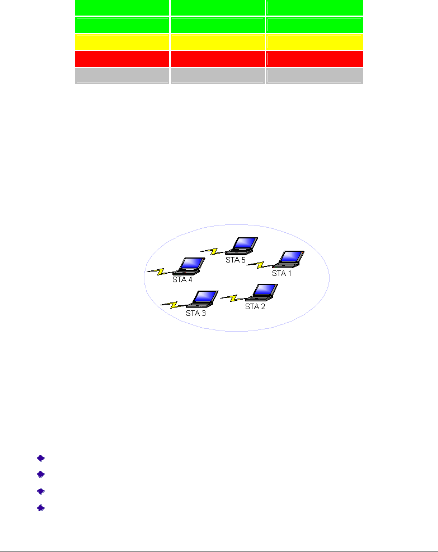
24 •
002?
Color Quality RSSI*
- "7 <Z
- - I'<Z
92 ) &'I<
# ) [&<
- 3 3
P##%%*1<1"
Ad Hoc Mode
22/12/21
5<%%62
215)6
2/0100"#
$$#$%$!
Ad Hoc Mode Profile Configuration
01032/ 1)0
,V0?
32/35- 6
)2;
KII)50KII6
+,+%!32/
• 25
,/-%
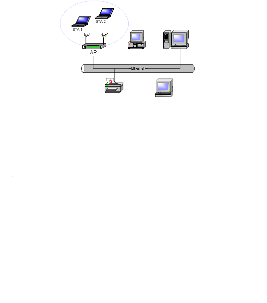
Infrastructure (Access Point) Mode
0515)6622/111
5<%%62
)
12/01001.
Infrastructure (Access Point) Mode Profile Configuration
010051632/ 1
10?
)2%,
KII)50KII6
+,
KII,
,/-%
To connect to an access point network, configure the profile for access point mode.
Infrastructure (Access Point) Mode Profile Configuration
To configure a profile in infrastructure (access point) mode, change the Network
Type in the Advanced tab. For access point mode, modify the settings:
Power Save Mode
802.11b Preamble (if using 802.11b)
Wireless Mode
802.11 Authentication Mode

26 •
Uninstall an Old Driver
(0123*%
200
103*%1%1N
I 3*%0$%*,'/WNC
#&7+32/1(
/$8
M +0*,0
0
-%%A
"$%#%000?0
WNC7?0
/%32020101
11
000
N 10'"((%00
)*+,,)-").
Additional Security Features
01/22/V+")/ 2
111000
1
Message Integrity Check (MIC)
,1'01/11/'01/
110
1 ,1/1
1
Temporal Key Integrity Protocol (TKIP)
01/+")211/
.5:61+")/ 8)
11+")/
Broadcast Key Rotation
")1+")/021
/+")/111
+")/

• 27
Advanced Status Information
/%0WNC(
011 %
D0 020
%
Network Name (SSID)*122/
02/-
Server Based
Authentication%22
Data Encryption*1110
11%
Authentication Type*1
0-
Message Integrity
Check%22,,1'01/
11/
Associated AP Name*10121
Associated AP IP
Address%2)0121
Associated AP MAC
Address*1,012
1
Power Save Mode%212)2
012
Current Power Level*112+
Current Signal Strength%2<
Current Noise Level*1<
Up Time%221125
??6010N
12???
802.11b Preamble*1KII10
010
Current Receive Rate%2,1
Current Transmit Rate*1,1
Channel%2
Frequency*10D
Channel Set%2

28 •
Regulatory Compliance Notices
USA-Federal Communications Commission (FCC)
#'D"71U11?
*\?NKR-DNXA116
I 110
01
'142
$0*?NKR-DNXA1162
M +,2
10D1.
D
N 0?W
*?NKR-DNXA116W
& 01
2
NKR-DNXA11620S
21
12020D0
D10120<
1)I&0# 11
00 D1
0D02
00!2
0210D10
012D1
0000
02?
'#
'2D1
'D10002
'71L :01
This device complies with Part 15 of the FCC Rules. Operation is subject to the following two
conditions: (1) This device may not cause harmful interference, and (2) this device must accept
any interference received, including interference that may cause undesired operation.
FCC Caution: Any changes or modifications not expressly approved by the party responsible for
compliance could void the user's authority to operate this equipment.

• 29
IMPORTANT NOTE:
/0123
D1 12710 0
D1 1 2
2U
'142
$1&I&'&&-!.
IMPORTANT NOTE: In the event that these conditions can not be met (for example certain laptop
configurations or co-location with another transmitter), then the FCC authorization is no longer considered
valid and the FCC ID can not be used on the final product. In these circumstances, the OEM integrator will
be responsible for re-evaluating the end product (including the transmitter) and obtaining a separate FCC
authorization.
End Product Labeling
This transmitter module is authorized only for use in device where the antenna may be installed such that 20 cm
may be maintained between the antenna and users. The final end product must be labeled in a visible area with
the following: “Contains FCC ID:NKR-DNXA116”.
Manual Information To the End User
The OEM integrator has to be aware not to provide information to the end user regarding how to install or
remove this RF module in the user’s manual of the end product which integrates this module.
The end user manual shall include all required regulatory information/warning as show in this manual.
IMPORTANT NOTE: In the event that these conditions can not be met (for example certain laptop
configurations or co-location with another transmitter), then the FCC authorization is no longer considered valid
and the FCC ID can not be used on the final product. In these circumstances, the OEM integrator will be
responsible for re-evaluating the end product (including the transmitter) and obtaining a separate FCC
authorization.
End Product Labeling This transmitter module is authorized only for use in device where the antenna may be
installed such that 20 cm may be maintained between the antenna and users. The final end product must be
labeled in a visible area with the following: “Contains FCC ID:NKR-DNXA116”.
Manual Information To the End User
The OEM integrator has to be aware not to provide information to the end user regarding how to install or remove
this RF module in the user’s manual of the end product which integrates this module. The end user manual shall
include all required regulatory information/warning as show in this manual.

• 31
S0$",0201
W,)$# 3 3$ "? 12#711D
'142
X
Caution:
0&I&'&&,!.0100
0'
<121516&&'
&M&,!.&&'&K&,!.0L
71;3