Wistron NeWeb IMG2 IMG2 LTE module User Manual 1

Wistron NeWeb Corporation IMG2 LTE module 1

Contents

Doc-User Manual_R2.pdf
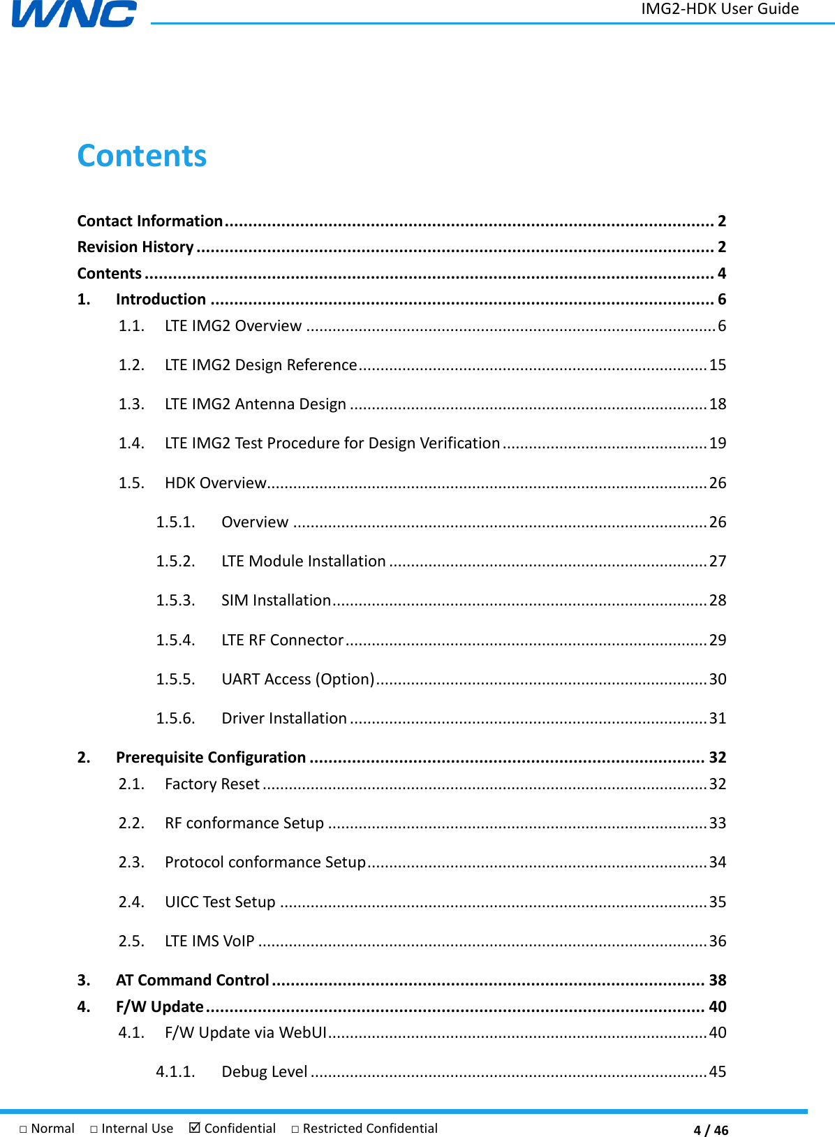
 1 / 46 □ Normal  □ Internal Use   Confidential  □ Restricted Confidential                 IMG2 User Guide V1.0     Author: Wistron NeWeb Corporation   Revision: 1.0 Revision Date: 2018/9/20
 2 / 46 IMG2-HDK User Guide □ Normal  □ Internal Use   Confidential  □ Restricted Confidential Contact Information Company Website www.wnc.com.tw   Revision History Rev. # Author Summary of Changes Date 1.0 WNC   First release. 2018/09/20
 3 / 46 IMG2-HDK User Guide □ Normal  □ Internal Use   Confidential  □ Restricted Confidential ©  Wistron NeWeb Corporation THIS DOCUMENT AND THE INFORMATION CONTAINED HEREIN IS PROPRIETARY AND IS THE EXCLUSIVE PROPERTY OF WNC AND SHALL NOT BE DISTRIBUTED, REPRODUCED, OR DISCLOSED IN WHOLE OR IN PART WITHOUT PRIOR WRITTEN PERMISSION FROM WNC.   LIMITATION OF LIABILITY THIS DOCUMENT AND THE INFORMATION CONTAINED HEREIN IS PURELY FOR DESIGN REFERENCE AND SUBJECT TO REVISION BY WNC AT ANY TIME. NOTHING IN THIS DOCUMENT SHALL BE CONSTRUED AS GRANTING ANY WARRANTY OR RIGHT TO USE THE MATERIAL CONTAINED HEREIN WITHOUT WNC’S PRIOR EXPRESS WRITTEN CONSENT. WNC SHALL NOT BE LIABLE FOR ANY USE, APPLICATION OR DEVELOPMENT DERIVED FROM THE MATERIAL WITHOUT SUCH PRIOR EXPRESS WRITTEN CONSENT.
 4 / 46 IMG2-HDK User Guide □ Normal  □ Internal Use   Confidential  □ Restricted Confidential Contents Contact Information ........................................................................................................ 2 Revision History .............................................................................................................. 2 Contents ......................................................................................................................... 4 1. Introduction ........................................................................................................... 6 1.1.  LTE IMG2 Overview .............................................................................................. 6 1.2.  LTE IMG2 Design Reference ................................................................................ 15 1.3.  LTE IMG2 Antenna Design .................................................................................. 18 1.4.  LTE IMG2 Test Procedure for Design Verification ............................................... 19 1.5.  HDK Overview ..................................................................................................... 26 1.5.1.  Overview ............................................................................................... 26 1.5.2.  LTE Module Installation ......................................................................... 27 1.5.3.  SIM Installation ...................................................................................... 28 1.5.4.  LTE RF Connector ................................................................................... 29 1.5.5.  UART Access (Option) ............................................................................ 30 1.5.6.  Driver Installation .................................................................................. 31 2. Prerequisite Configuration .................................................................................... 32 2.1.  Factory Reset ...................................................................................................... 32 2.2.  RF conformance Setup ....................................................................................... 33 2.3.  Protocol conformance Setup .............................................................................. 34 2.4.  UICC Test Setup .................................................................................................. 35 2.5.  LTE IMS VoIP ....................................................................................................... 36 3. AT Command Control ............................................................................................ 38 4. F/W Update .......................................................................................................... 40 4.1.  F/W Update via WebUI ....................................................................................... 40 4.1.1.  Debug Level ........................................................................................... 45
 5 / 46 IMG2-HDK User Guide □ Normal  □ Internal Use   Confidential  □ Restricted Confidential 4.1.1.1.  IMS ......................................................................................................... 45 4.1.1.1.1.  Configuration to Enable IMS Debug Level ...................................... 45 4.1.1.1.2.  Get Log File from Device ................................................................ 46
 6 / 46 IMG2-HDK User Guide □ Normal  □ Internal Use   Confidential  □ Restricted Confidential 1. Introduction This document gives an instruction on how to use IMG2 module and HDK. 1.1. LTE IMG2 Overview     Form Factor: LGA   Dimension: 32x36x4.3(mm) DC Voltage: 3.3~4.3V
 7 / 46 IMG2-HDK User Guide □ Normal  □ Internal Use   Confidential  □ Restricted Confidential Block Diagram  Note:   1. Only using ANT1~ANT4, all of other antenna ports should be terminated by 50ohm load for module application, and which output performancs are guaranteed accordingly. 2. This module not certified for embedded antenna or hanheld devices
 8 / 46 IMG2-HDK User Guide □ Normal  □ Internal Use   Confidential  □ Restricted Confidential   Features: Platform: GCT GDM7243Q Support FDD Band 2/4/5/13   compliant with LTE specification (3GPP Release 10)   Support 1T2R Cat. 6 with downlink carrier aggression    Uplink: 50Mbps    Downlink: 300Mbps    Supports downlink inter and intra 2-Carrier Aggregation (Class C), 2+2, 5+5, 4+4 2+4, 2+5, 2+13, 4+5, 4+13, 5+13,    Support all LTE Bandwidth per 3GPP standard (1.4/3/5/10/15/20MHz)
 9 / 46 IMG2-HDK User Guide □ Normal  □ Internal Use   Confidential  □ Restricted Confidential  - Frequency Bands LTE     UL (MHz)   DL (MHz) TX Power Band 2   1850~1910 1930~1990 23 +/-2.7dBm Band 4   1710~1755 2110~2155 23 +/-2.7dBm Band 5 824~849 869~894 23 +/-2.7dBm Band 13 777~787 746~756 23 +/-2.7dBm    a) LGA PCB footprint
 10 / 46 IMG2-HDK User Guide □ Normal  □ Internal Use   Confidential  □ Restricted Confidential  b) LGA Pin Assignments Pin # ETSI Pin assign in ETSI Spec LGA IMG2 LGA IMG2 Description   Signal Dir Level Signal Dir Level   1 GND             2 GND             3 RF_GNSS     NC     Antenna for a GNSS receiver 4 GND             5 GND             6 GND             7 LB_RF1             8 GND             9 GND             10 GND             11 LB_RF2             12 GND             13 GND             14 GND             15 LB_RF3             16 GND             17 GND             18 GND             19 LB_RF4             20 GND             21 GND             22 GND             23 HB_RF1             24 GND             25 GND             26 GND
 11 / 46 IMG2-HDK User Guide □ Normal  □ Internal Use   Confidential  □ Restricted Confidential 27 HB_RF2             28 GND             29 GND             30 GND             31 HB_RF3             32 GND             33 GND             34 GND             35 HB_RF4             36 GND             37 VCC1           Power (Typ=3.8V,   Min=3.4V, Max=4.2V) 38 VCC2           Power (Typ=3.8V,   Min=3.4V, Max=4.2V) 39 VCC3           Power (Typ=3.8V,   Min=3.4V, Max=4.2V) 40 VCC4           Power (Typ=3.8V,   Min=3.4V, Max=4.2V) 41 VCC5           Power (Typ=3.8V,   Min=3.4V, Max=4.2V) 42 VCC6           Power (Typ=3.8V,   Min=3.4V, Max=4.2V) 43 RTC_POWER     NC     Typ=3.0V, Min=2.0V, Max=3.25V 44 GND             45 GND             46 PCM_SYNC/I2S_WS     PCM_SYNC O 1.8V   47 PCM_DIN/I2S_DIN     PCM_IN I 1.8V
 12 / 46 IMG2-HDK User Guide □ Normal  □ Internal Use   Confidential  □ Restricted Confidential 48 PCM_DOUT/I2S_DOUT     PCM_OUT O 1.8V   49 PCM_CLK/I2S_CLK     PCM_MCLK O 1.8V   50 GND             51 GND             52 GPIO01   VREF UART0_TXD O 1.8V   53 GPIO02   VREF UART0_RXD I 1.8V   54 GPIO03   VREF W_DISABLE#1 I 3.3V   55 GPIO04   VREF W_DISABLE#2 I 1.8V   56 GPP01     I2C_CLK O 1.8V   57 GPP02     I2C_SDA B 1.8V   58 GPP03             59 GPP04     RGMII_MDC   3.3V RGMII Signals 60 GPP05     RGMII_MDIO   61 GPP06     RGMII_TCLK   62 GPP07     RGMII_TCTL   63 GPP08     RGMII_TXD0   64 RFU     RGMII_TXD1   65 RFU     RGMII_TXD2   66 RFU     RGMII_TXD3   67 RFU     RGMII_RXD0   68 RFU     RGMII_RXD1   69 RFU     RGMII_RXD2   70 RFU     RGMII_RXD3   71 RFU     RGMII_RCLK   72 RFU     RGMII_RCTL   73 RFU     PHY2MAC_125Mhz     74 GND             75 GND             76 UART1_DTR   VREF UART2_RXD   VREF(1.8V)   77 UART1_RING   VREF UART2_TXD   VREF(1.8V)   78 UART1_DCD   VREF COEX3   VREF(1.8V)   79 UART1_DSR   VREF     VREF(1.8V)   80 UART1_CTS   VREF UART3_CTS   VREF(1.8V)   81 UART1_RTS   VREF UART3_RTS   VREF(1.8V)   82 UART1_RX   VREF UART3_RXD   VREF(1.8V)
 13 / 46 IMG2-HDK User Guide □ Normal  □ Internal Use   Confidential  □ Restricted Confidential 83 UART1_TX   VREF UART3_TXD   VREF(1.8V)   84 GND             85 GND             86 USB_DP     USB2.0_DP B     87 VBUS/GPIO87       I     88 UAB_DM     USB2.0_DM B     89 GND             90 GND             91 GND             92 USB3_SSTXn       USB3.0-SSTX- B     93 PCIe_CLKREQ/MPHY_SB1     NC       94 USB3_SSTXp     USB3.0-SSTX+ B     95 PCI#_WAKE     NC       96 USB3_SSRXn     USB3.0-SSRX- B     97 PCIe_RST     NC       98 USB3_SSRXp     USB3.0-SSRX+ B     99 USB_STROBE     NC       100 USB_DATA     NC       101 MPHY_TX2_DP     NC       102 PCIe_REFCLKn/MPHY_RX2_DN     NC       103 PCIe_REFCLKp/MPHY_RX2_DP     NC       104 GND             105 GND             106 UART2_RX   VREF UART1_RXD   VREF(1.8V)   107 UART2_TX   VREF UART1_TXD   VREF(1.8V)   108 GND             109 GND             110 RFU     SPI_CS2# O 1.8V   111 RFU     SPI_SCLK O 1.8V   112 RFU     SPI_MOSI O 1.8V   113 RFU     SPI_MISO I 1.8V   114 RFU     SLIC_RST# O 1.8V   115 RFU     SLIC_INT# I 1.8V   116 RFU     GPS_SYNC O
 14 / 46 IMG2-HDK User Guide □ Normal  □ Internal Use   Confidential  □ Restricted Confidential 117 RFU     GPS_ENABLE O     118 RFU     CLKOUT_GPS O     119 RFU     ETH_EN       120 GPP09     SDH0_CLK O 1.8V   121 GPP10     SCH0_CMD O 1.8V   122 GPP11     SDH0_DAT0 B 1.8V   123 GPP12     SDH0_DAT1 B 1.8V   124 GPP13     SDH0_DAT2 B 1.8V   125 GPP14     SDH0_DAT3 B 1.8V   126 GPP15     SDH0_CD# B 1.8V   127 GPP16     DPR I 1.8V   128 GPP17     SDH0(WIFI)_RST#       129 GPIO05   VREF ANTCTL0 O 1.8V   130 GPIO06   VREF ANTCTL1 O 1.8V   131 GPIO07   VREF ANTCTL2 O 1.8V   132 GPIO08   VREF ANTCTL3 O 1.8V   133 UIM_VCC O 1.8/3.0V SIM_VCC O 1.8/3.0V   134 UIM_DAT B 1.8/3.0V SIM_DAT B 1.8/3.0V   135 UIM_CLK O 1.8/3.0V SIM_CLK O 1.8/3.0V   136 UIM_RESET O 1.8/3.0V SIM_RST O 1.8/3.0V   137 UIM_DETECT I 1.8/3.0V NC I 1.8/3.0V   138 UIM_SPU TBD   NC TBD     139 GND             140 GND             141 WWAN_STATE O VREF NC O 1.8V/3.3V   142 POWER_ON I VREF ENABLE_MODULE I VREF(1.8V)   143 WAKEUP_OUT/GPIO143 O VREF WAKEUP#_HOST O VREF(1.8V)   144 WAKEUP_IN/GPIO144 I VREF WAKEUP#_LTE I VREF(1.8V)   145 RESET I VREF RESET#_1.8V I VREF(1.8V)   146 VREF O   1.8V O DCDC_1.8V
 15 / 46 IMG2-HDK User Guide □ Normal  □ Internal Use   Confidential  □ Restricted Confidential   1.2. LTE IMG2 Design Reference LTE Module IMG2 on EVK M.2 PCBA with RF Switch connectors (ANT1~ANT4).        EVK PCB Structure 類型 Type 鑽孔構造 Drill Structure 層別 Layer 假設的殘銅率(%) Assumptive copper area (%)   材料型號 Material Type ER (@2GHZ) Thickness after Process   (mil) (mm) GT P/N: 18012203-03     Top Solder Mask     3.8 1.00   0.025   Metal     L1   Base Cu + Plating   1.40   0.036
 16 / 46 IMG2-HDK User Guide □ Normal  □ Internal Use   Confidential  □ Restricted Confidential Dielectric   Prepreg   2116*2 4 9.37   0.238   Metal   L2 75.0% 1OZ   1.15   0.029   Dielectric   Core   0.005" 4.2 5.00   0.127   Metal   L3 75.0% 1OZ   1.15   0.029   Dielectric   Prepreg   2116*2 4 9.37   0.238   Metal   L4   Base Cu + Plating   1.40   0.036       Bottom Solder Mask     3.8 1.00   0.025     Board thickness :    0.8mm+/-10%(Including Plating+S/M)   Total : 30.84   0.783     RF Trace Impedance Table  NO. 控制層 Layer 阻值要求 Impedance Requirement (ohms) Tolerance 阻抗類型 Impedance   Type 參考層 Ref. Layer 線寬 Trace Width (mil) 線距 Trace Spacing (mil) Line to gnd space (mil) 计算值 Calculated Values (ohms) 1 L1 50 +/-10% Coplanar Single L2 15 - 10 49.8 2 L4 50 +/-10% Coplanar Single L3 15 - 10 49.8   Layout guidelines for RF trace outputs
 17 / 46 IMG2-HDK User Guide □ Normal  □ Internal Use   Confidential  □ Restricted Confidential   All PJ2/PJ7/PJ4/PJ5 connectors are RF switch connectors and the part description as below. “INTERNAL CONNECTOR,MICRO RF SWSMT,180DEG.,JACK,RF SWITCH,(FOXCONN),KMC1001-F007-7F”. The main purpose of these RF switches is to verify the conductive TRX RF performances or for debugging.  Some key performances should be verified: i)  TX Power Level ii)  Spectrum Emmission Mask iii)  RX Sensitivity iv)  EVM v)  Frequency Error vi)  VSWR
 18 / 46 IMG2-HDK User Guide □ Normal  □ Internal Use   Confidential  □ Restricted Confidential 1.3. LTE IMG2 Antenna Design    The antenna should be 50ohm characteristic impedance with Return Loss less than -10dB at all desired frequency bands.The following external antenna as an example for OEM verifications because this special dipole antenna being certified with IMG2 LTE module. Manufactured by MAGLAYERS Model Name: WDA-2010-4G0R2-A1       Outlines of external antenna     Return loss <= -10dB
 19 / 46 IMG2-HDK User Guide □ Normal  □ Internal Use   Confidential  □ Restricted Confidential   1.4. LTE IMG2 Test Procedure for Design Verification   Equipment List
 20 / 46 IMG2-HDK User Guide □ Normal  □ Internal Use   Confidential  □ Restricted Confidential Item Quantity Specification KS E6640A 1  Shielding box 1  PC 1   DC Power Supply 1 PPT-3615 USB Cable 2   Ethernet Cable 1  Test fixture 1            LTE Test Plan
 21 / 46 IMG2-HDK User Guide □ Normal  □ Internal Use   Confidential  □ Restricted Confidential          LTE Test Spec.
 22 / 46 IMG2-HDK User Guide □ Normal  □ Internal Use   Confidential  □ Restricted Confidential
 23 / 46 IMG2-HDK User Guide □ Normal  □ Internal Use   Confidential  □ Restricted Confidential
 24 / 46 IMG2-HDK User Guide □ Normal  □ Internal Use   Confidential  □ Restricted Confidential
 25 / 46 IMG2-HDK User Guide □ Normal  □ Internal Use   Confidential  □ Restricted Confidential
 26 / 46 IMG2-HDK User Guide □ Normal  □ Internal Use   Confidential  □ Restricted Confidential 1.5. HDK Overview 1.5.1. Overview
 27 / 46 IMG2-HDK User Guide □ Normal  □ Internal Use   Confidential  □ Restricted Confidential 1.5.2. LTE Module Installation Three steps to accomplish module installation:   Step1. Insert module with about 15° angle to NGFF connector.   Step2. Press down the module.   Step3. Fasten with a screw.
 28 / 46 IMG2-HDK User Guide □ Normal  □ Internal Use   Confidential  □ Restricted Confidential 1.5.3. SIM Installation
 29 / 46 IMG2-HDK User Guide □ Normal  □ Internal Use   Confidential  □ Restricted Confidential 1.5.4. LTE RF Connector LTE RF connection is RF cable type dependency. That said, only Murata cable can be used while doing conductive test.
 30 / 46 IMG2-HDK User Guide □ Normal  □ Internal Use   Confidential  □ Restricted Confidential 1.5.5. UART Access (Option) 4 PIN UART provides LTE module UART access. Generally it is used for debugging and an RS232-to-USB adaptor is required. Baud rate is 921600.
 31 / 46 IMG2-HDK User Guide □ Normal  □ Internal Use   Confidential  □ Restricted Confidential 1.5.6. Driver Installation The communication between DUT and PC is Ethernet-over-USB. Please install driver (i.e., dpinst.exe) on a PC first.  TOOL-Windows RNDISACM Driver Installer for Vista and later GDM7243_windows_acm_drivers_installer_v1.1.0.0 32bit dpinst.exe 64bit dpinst.exe for XP GDM7243_windows_xp_acm_rndis_installer_v.1.3.0.0 dpinst.exe  Two interfaces are derived when connecting USB connector to PC.  USB RNDIS : network interface  Modem Com port : AT command interface which supports baud rate: 921600 at most In device manager, you will see an RNDIS interface and a Modem COM port after DUT boots up completely. PC will obtain an IP address of 192.168.0.X assigned by DUT via DHCP.
 32 / 46 IMG2-HDK User Guide □ Normal  □ Internal Use   Confidential  □ Restricted Confidential 2. Prerequisite Configuration 2.1. Factory Reset This section provides a way to execute “Factory Reset”. SDM parameter values will be persistent throughout “Factory Reset”. “Factory Reset” is applied to Motive testing, 7Layers OTADM testing and Field testing. It is used during the testing while “Factory Reset ” is needed. Step 1 Power on DUT and then wait a while (i.e., around 20 sec). Step 2 Make sure a Modem COM port is observed in device manager. (Please refer to section 1.1.6) This Modem COM port (i.e., AT command interface) can simply connected through generic UART console program such as “TeraTerm”, “putty”, etc,… Step 3 (a.) Type shell (b.) Type shell command: ucfg sync  Step 4 ※Then a DUT reboot is required to apply the setting.
 33 / 46 IMG2-HDK User Guide □ Normal  □ Internal Use   Confidential  □ Restricted Confidential 2.2. RF conformance Setup  This section is applied to RF conformance test such as GCF - TS 36.521-1: Evolved Universal Terrestrial Radio Access (E-UTRA); User Equipment (UE) conformance specification; Radio transmission and reception; Part 1: Conformance testing - TS 36.521-3: Evolved Universal Terrestrial Radio Access (E-UTRA); User Equipment (UE) conformance specification; Radio transmission and reception; Part 3: Radio Resource Management (RRM) conformance testing   Prior to test please have “Factory Reset” for DUT as described in section 2.1. Besides, RF conformance test just uses the internet PDN. And, UL data should be blocked. The instruction is shown as following; Step 1 Power on DUT and then wait a while (i.e., around 20 sec). Step 2 Make sure a Modem COM port is observed in device manager. (Please refer to section 1.1.6) This Modem COM port (i.e., AT command interface) can simply connected through generic UART console program such as “TeraTerm”, “putty”, etc,… Step 3 (a.) Type AT command: AT%SYSCMD="ucfg set config wan lte ims ims_test_mode 1" (b.) Type AT command: AT%PKTDISCARD=1  Step 4 ※Then a DUT reboot is required to apply the setting.   In order to avoid DUT incorrect operation caused by manually changing it for test purpose. While DUT is reused for another test plan please change it back as following, (a.) Type AT command: AT%PKTDISCARD=0 (b.) Type AT command: AT%MIMOANTCHECK=0
 34 / 46 IMG2-HDK User Guide □ Normal  □ Internal Use   Confidential  □ Restricted Confidential 2.3. Protocol conformance Setup  This section is applied to Protocol conformance test such as GCF - TS 36.523-1: Evolved Universal Terrestrial Radio Access (E-UTRA) and Evolved Packet Core (EPC); User Equipment (UE) conformance specification; Part 1: Protocol conformance specification   Prior to test please have “Factory Reset” for DUT as described in section 2.1. Besides, Protocol conformance test just uses the internet PDN. And, UL data should be blocked. The instruction is shown as following; Step 1 Power on DUT and then wait a while (i.e., around 20 sec). Step 2 Make sure a Modem COM port is observed in device manager. (Please refer to section 1.1.6) This Modem COM port (i.e., AT command interface) can simply connected through generic UART console program such as “TeraTerm”, “putty”, etc,… Step 3 (a.) Type AT command: AT%SYSCMD="ucfg set config wan lte ims ims_test_mode 1" (b.) Type AT command: AT%PKTDISCARD=1  Step 4 ※Then a DUT reboot is required to apply the setting.   In order to avoid DUT incorrect operation caused by manually changing it for test purpose. While DUT is reused for another test plan please change it back as following, (c.) Type AT command: AT%PKTDISCARD=0 (d.) Type AT command: AT%MIMOANTCHECK=0
 35 / 46 IMG2-HDK User Guide □ Normal  □ Internal Use   Confidential  □ Restricted Confidential 2.4. UICC Test Setup  This section is applied to UICC test such as GCF - TS 31.121: UICC-terminal interface; Universal Subscriber Identity Module (USIM) application test specification - TS 31.124: Mobile Equipment (ME) conformance test specification; Universal Subscriber Identity Module Application Toolkit (USAT) conformance test specification - TS 102.230: Smart Cards; UICC-Terminal interface; Physical, electrical and logical test specification   Please refer to G7243_USAT_Test_Guide_v2.5.pdf
 36 / 46 IMG2-HDK User Guide □ Normal  □ Internal Use   Confidential  □ Restricted Confidential 2.5. LTE IMS VoIP This section provides commands for configuration change requirement. Commands are marked in red. Please input command in # prompt.   Please not that if you apply “Factory Reset” in section 2.1, it will set all VoIP parameters to device’s default values.  1). IMS RTP RTCP Inactivity Timer Command ucfg set config wan lte ims volte rtp_rtcp_inactivity_timer_ims <value>   Description This parameter indicates the maximum length of time a call can remain active without any media (RTP or RTCP) traffic within a group. Each time an RTP or RTCP packet occurs within a call, this timeout resets. The value is an integer measured in Seconds. Example Note: set rtcp_inactivity_timer to 300s ucfg set config wan lte ims volte rtp_rtcp_inactivity_timer_ims 300  Get current setting from device ucfg get config wan lte ims volte rtp_rtcp_inactivity_timer_ims  2). IMS Session Timer Command ucfg set config wan lte ims volte session_timer_ims <value>   Description The Session-Expires header value can be configured through the SESSION-EXP tag. Session-Expires conveys the duration of the session. SIP entities MUST be prepared to handle Session-Expires header field values of any duration greater than 90 Seconds. Small session intervals can be destructive to the network. They cause excessive messaging traffic that affects both user agents and proxy servers. More information about Session Expires and Min-Session Expire can be found in RFC 4028. The value is an integer measured in Seconds. Example Note: set session_timer_ims to 90 seconds ucfg set config wan lte ims volte session_timer_ims 90  Get current setting from device ucfg get config wan lte ims volte session_timer_ims  3). IMS Min Se Timer Command ucfg set config wan lte ims volte min_se_ims <value>   Description The minimum value for session-expires value The Min-SE header field indicates the minimum value for the session interval, in units of seconds. The value of this element is inserted in MIN-SE header in INVITE request. The value must be greater than 90 seconds. More information about Session Expires and Min-Session Expire can be found in RFC 4028. The value is an integer measured in Seconds. Example Note: set min_se_ims to 90 seconds ucfg set config wan lte ims volte min_se_ims 90  Get current setting from device ucfg get config wan lte ims volte min_se_ims
 37 / 46 IMG2-HDK User Guide □ Normal  □ Internal Use   Confidential  □ Restricted Confidential 4). Enable/Disable SCR_AMRWB Command ucfg set config wan lte ims volte scr_amrwb <value>   Example Note: enable SCR_AMRWB ucfg set config wan lte ims volte scr_amrwb 1 Note: disable SCR_AMRWB ucfg set config wan lte ims volte scr_amrwb 0  Get current setting from device ucfg get config wan lte ims volte scr_amrwb  5). Enable/Disable AMR_WB Command ucfg set config wan lte ims volte scr_amrwb <value>   Example Note: enable AMR_WB ucfg set config wan lte ims volte amrwb 1 Note: disable AMR_WB ucfg set config wan lte ims volte amrwb 0  Get current setting from device ucfg get config wan lte ims volte amrwb  6). Set AMR_WB Mode Command ucfg set config wan lte ims volte amrwbmodset <value>   Example Note: set amrwbmodeset parameter 8 ucfg set config wan lte ims volte amrwbmodset 8 Note: set amrwbmodeset parameter to "0,1,2" ucfg set config wan lte ims volte amrwbmodset 0,1,2 Note: set amrwbmodeset parameter to "0,2,5,7" ucfg set config wan lte ims volte amrwbmodset 0,2,5,7  Get current setting from device ucfg get config wan lte ims volte amrwbmodset  7). Set TTY Mode Command ucfg set config wan lte ims volte tty_mode <value>   Example Note: set TTY mode to TTY FULL ucfg set config wan lte ims volte tty_mode 3 Note: set TTY mode to TTY HCO ucfg set config wan lte ims volte tty_mode 1 Note: set TTY mode to TTY VCO ucfg set config wan lte ims volte tty_mode 2 Note: set TTY mode to TTY OFF ucfg set config wan lte ims volte tty_mode 0  Get current setting from device ucfg get config wan lte ims volte tty_mode
 38 / 46 IMG2-HDK User Guide □ Normal  □ Internal Use   Confidential  □ Restricted Confidential 3. AT Command Control Tester can enter 3GPP AT Command through “GCT GDM7243 LTE USB Monitor Port” interface (i.e., section 1.1.6) and it can simply connected through generic UART console program such as “TeraTerm”, “putty”, etc,… Some proprietary AT commands and VzW AT commands support for testing purpose as followings; Antenna Selection This command will persist through power cycle (A.) Set command Usage AT%MIMOANTCHECK=0   AT%MIMOANTCHECK=1 AT%MIMOANTCHECK=2 AT%MIMOANTCHECK? Description Enable Main & Div. Enable Div. only Enable Main only Query current enabled antenna port  +MIMOANTCHECK : 0 (B.) Read command returns the current setting of <+MIMOANTCHECK :> Usage AT%MIMOANTCHECK? Response +MIMOANTCHECK : 0    both Main & Div are enabled +MIMOANTCHECK : 1      only Div is enabled +MIMOANTCHECK : 2      only Main is enabled  Read RSRP Usage AT+VZWRSRP? Response +VZWRSRP: <cellID>1,<EARFCN>1,<RSRP>1,<cellID>2,<EARFCN>2,<RSRP>2,…,<cellID>n, <EARFCN>n,<RSRP>n +CME ERROR: <err>  Read RSRQ Usage AT+VZWRSRQ? Response +VZWRSRQ: <cellID>1,<EARFCN>1,<RSRQ>1,<cellID>2,<EARFCN>2,<RSRQ>2,…,<cellID>n,<EARFCN>n,<RSRQ>n +CME ERROR: <err>  Edit APN Table This command will persist through power cycle (A.) Set command Usage AT+VZWAPNE=<wapn>,<apncl>,<apnni>,<apntype>,<apnb>,<apned> Description <wapn> index digit <apncl>: class digit <apnni>: name string <apntype>: type string <apnb>: bearer string <apned> string 1, 2 or 3 1, 2 or 3  IPv4 IPv6 IPv4v6 LTE Enabled   Disabled Note (i) <wapn> and <apncl> should be the same (ii) Since it is LTE only device, <apnb> should be given as LTE Example Edit 3rd APN. Give APN name as empty; APN type as IPV4; APN bearer as LTE and 3rd APN is enabled AT+VZWAPNE=3,3,,IPv4,LTE,Enabled (B.) Read command returns the current setting of <+VZWAPNE :> Usage AT+VZWAPNE? Response 1,IMS,IPv4v6,LTE,Enabled,0, 2,VZWADMIN,IPv4v6,LTE,Enabled,0, 3,VZWINTERNET,IPv4v6,LTE,Enabled,0, 4,VZWAPP,IPv4v6,LTE,Enabled,0,
 39 / 46 IMG2-HDK User Guide □ Normal  □ Internal Use   Confidential  □ Restricted Confidential Enable/Disable packet discard This command will persist through power cycle (A.) Set command Usage AT%PKTDISCARD=1   AT%PKTDISCARD=0 Description Discard the UL packet Back to normal operation (B.) Read command returns the current setting of <+MIMOANTCHECK :> Usage AT%PKTDISCARD? Response +PKTDISCARD : OFF    back to normal operation +PKTDISCARD : ON    discard the UL packet  Enable/Disable packet discard This command will NOT persist through power cycle Usage AT%GSWTESTW=3,1 AT%GSWTESTW=3,0 Description Discard the UL packet Back to normal operation  Clear RPLMN list Usage AT%VZWMRUC  Clear FPLMN list Usage AT+CRSM=214,28539,0,0,0,"FFFFFFFFFFFFFFFFFFFFFFFF"
 40 / 46 IMG2-HDK User Guide □ Normal  □ Internal Use   Confidential  □ Restricted Confidential 4. F/W Update 4.1. F/W Update via WebUI Step 1 Power on DUT and then wait a while (i.e., around 20 sec) Step 2 Make sure it can ping to DUT (i.e., 192.168.0.1) from PC (e.g., 192.168.0.X) Step 3 (a.) Navigate WebUI (i.e., http://192.168.0.1) (b.) Select Filename1=Bootloader, Filename2=Kernel, Filename3=Filesystem, Filename4=Modem Image to be downloaded. (It should be selected at least one file among four to go on updating process). Generally we will provide Kernel and Filesystem image. (c.) Click “Update” button to go on updating process  (d.) Click “OK” button to be continue while a prompt box displays
 41 / 46 IMG2-HDK User Guide □ Normal  □ Internal Use   Confidential  □ Restricted Confidential Step 4 Make sure a Modem COM port is observed in device manager. (Please refer to section 1.1.6) This Modem COM port (i.e., AT command interface) can simply connected through generic UART console program such as “TeraTerm”, “putty”, etc,… Step 5 (e.) Type AT command: AT%SYSCMD="ucfg clean config" (f.) Type AT command: AT%SYSCMD="ucfg clean factory"  Step 6 ※Then a DUT reboot is required to apply the setting.
 42 / 46 IMG2-HDK User Guide □ Normal  □ Internal Use   Confidential  □ Restricted Confidential Step 4 (a.) File => New connection…  (b.) Click “TCP/IP” radio button; select “Telnet” radio button; give an IP address of 192.168.0.1 and then press “OK” button.  (c.) Click “TCP/IP” radio button; select “Telnet” radio button; give an IP address of 192.168.0.1 and then press “OK” button. (a.) DUT Username: root; Password: gct
 43 / 46 IMG2-HDK User Guide □ Normal  □ Internal Use   Confidential  □ Restricted Confidential  Step 5 Type commands sequentially below: 1. ucfg get config wan lte 2. lted_cli 3. arm1log 2 4. AT%PKTDISCARD?
 44 / 46 IMG2-HDK User Guide □ Normal  □ Internal Use   Confidential  □ Restricted Confidential    Step 6 Run test case Step 7 Press “Close” button after test case stop.
 45 / 46 IMG2-HDK User Guide □ Normal  □ Internal Use   Confidential  □ Restricted Confidential 4.2. Debug Level An introduction to enable default debug level is described in Section 5.2. Furthermore, this subsection illustrates on how to enable a specific debug level.   4.2.1. IMS 4.2.1.1. Configuration to Enable IMS Debug Level After applying configuration, it will store in device’s NV. However, it is different from default debug level. That said, it will be invalid after you restore device to factory default. Step 5 gives a way to quickly check and confirm whether the device is already enabled this specific debug level or not.   Note: commands are mark in red Step 1 Power on DUT and then wait a while (i.e., around 20 sec). Step 2 Please have UART access. (Hint: section 1.1.5) COM port can simply connect through generic UART console program such as “TeraTerm”. Step 3 (a.) Type command in DM> prompt: shell (b.) Type command in # prompt: ucfg set config wan lte ims debug_level 50  Step 4 ※Then a DUT reboot is required to apply above setting. Step 5 Please check and confirm if previous setting is applied. (a.) Type command in DM> prompt: shell (b.) Type command in # prompt: ucfg get config wan lte ims debug_level
 46 / 46 IMG2-HDK User Guide □ Normal  □ Internal Use   Confidential  □ Restricted Confidential 4.2.2. Get Log File from Device  Please have DUT set up properly based on section 1.1.6.   Step 1 Execute tfpd server running on PC side.  Step 2 (a.) Type command in DM> prompt: shell (b.) Type command in # prompt to get /var/log/EcrioSACALC.log from device to PC.

Navigation menu