Wistron NeWeb LMA18Q7 LTE Module User Manual UMC A18Q7 Rev 01 201609026
Wistron NeWeb Corporation LTE Module UMC A18Q7 Rev 01 201609026
User Manual
Subject: UMC-A18Q7 User Manual
REV: 0.1
PAGE 1 OF 21
Wistron Neweb Corporation Proprietary & Confidential
Design Document
UMC-A18Q7 User Manual
The document contains proprietary information which is the property of Wistron NeWeb
Corporation and is strictly confidential and shall not be disclosed to others in whole or in
part, reproduced, copied, or used as basic for design, manufacturing or sale of apparatus
without the written permission of Wistron NeWeb Corporation.
Subject: UMC-A18Q7 User Manual
REV: 0.1
PAGE 2 OF 21
Wistron Neweb Corporation Proprietary & Confidential
Design Document
Revision History
Issue Date Version Description
2016/09/06 0.1 Initial Issued
Subject: UMC-A18Q7 User Manual
REV: 0.1
PAGE 3 OF 21
Wistron Neweb Corporation Proprietary & Confidential
Design Document
Contents
1. Introduction .......................................................................................................................................... 4
2. Test Setup .............................................................................................................................................. 5
2.1 Developing board ..................................................................................................................... 5
2.2 HW connection and power on sequence ................................................................................ 7
2.3 Connectors and switches ......................................................................................................... 9
2.4 The configuration by adjusting jumpers .............................................................................. 10
3. Interfaces..............................................................................................................................................11
3.1 UART port ................................................................................................................................11
3.2 Android ADB interface ........................................................................................................... 13
3.3 Qualcomm HS-USB Diagnostics 9025 (COM port) ............................................................... 14
3.4 Qualcomm HS-USB WWAN Adapter 9025 ........................................................................... 14
3.5 Qualcomm HS-USB Android Modem 9025 ........................................................................... 15
4. Federal Communication Commission Interference Statement ....................................................... 16
Appendix I ................................................................................................................................................... 18
Subject: UMC-A18Q7 User Manual
REV: 0.1
PAGE 4 OF 21
Wistron Neweb Corporation Proprietary & Confidential
Design Document
1. Introduction
This User Manual of A18Q7 module is to describe how to use the following sections for
lab test by specific qualified engineers or technicians. Furthermore, this module is NOT
intended for commercial use but designed as part of Smart Meter product and M2M
devices which mainly provide 4G LTE WAN access capability.
FCC Interference Statement
This module complies with Part 15 of the FCC Rules. Operation is subject to the following
two conditions: (1) This module may not cause harmful interference and (2) this module
must accept any interference received, including interference that may cause undesired
operation.
Radiation Exposure Statement
This module complies with FCC radiation exposure limits set forth for an uncontrolled
environment. This module should be installed and operated with minimum distance of
20cm between radiator and human body.
Any changes or modifications not expressly approved by the party responsible for
compliance could void the user’s authority to operate the device.
Subject: UMC-A18Q7 User Manual
REV: 0.1
PAGE 5 OF 21
Wistron Neweb Corporation Proprietary & Confidential
Design Document
2. Test Setup
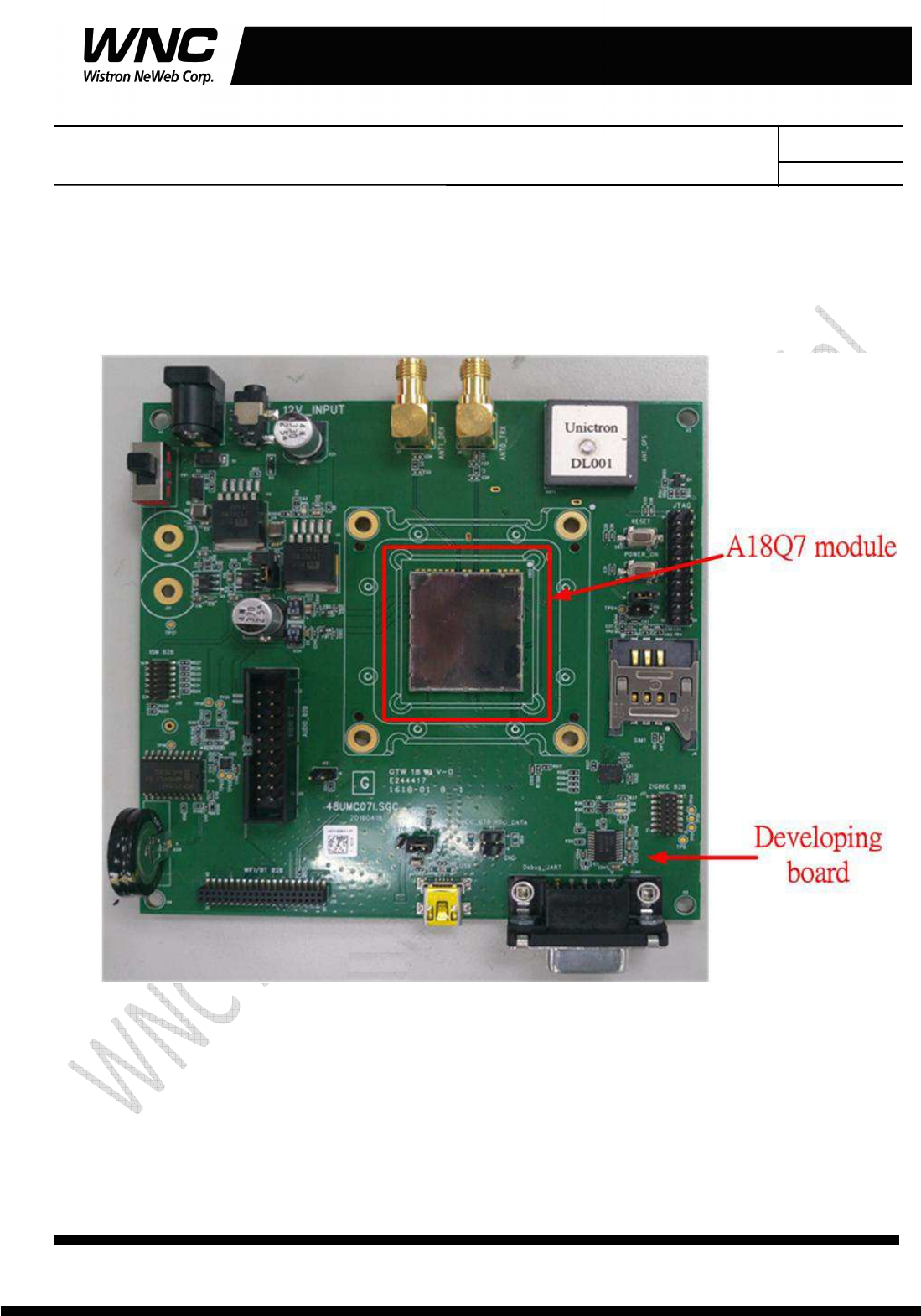
2.1 Developing board
The location of A18Q7:
Subject: UMC-A18Q7 User Manual
REV: 0.1
PAGE 6 OF 21
Wistron Neweb Corporation Proprietary & Confidential
Design Document
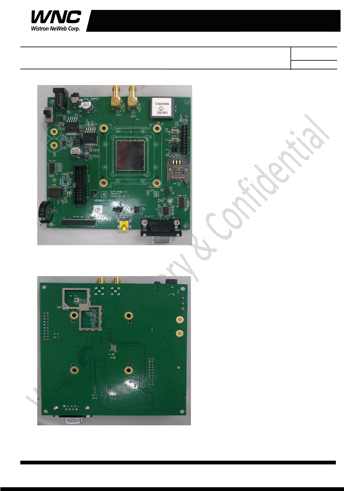
Top view:
Bottom view:
Subject: UMC-A18Q7 User Manual
REV: 0.1
PAGE 7 OF 21
Wistron Neweb Corporation Proprietary & Confidential
Design Document
2.2 HW connection and power on sequence
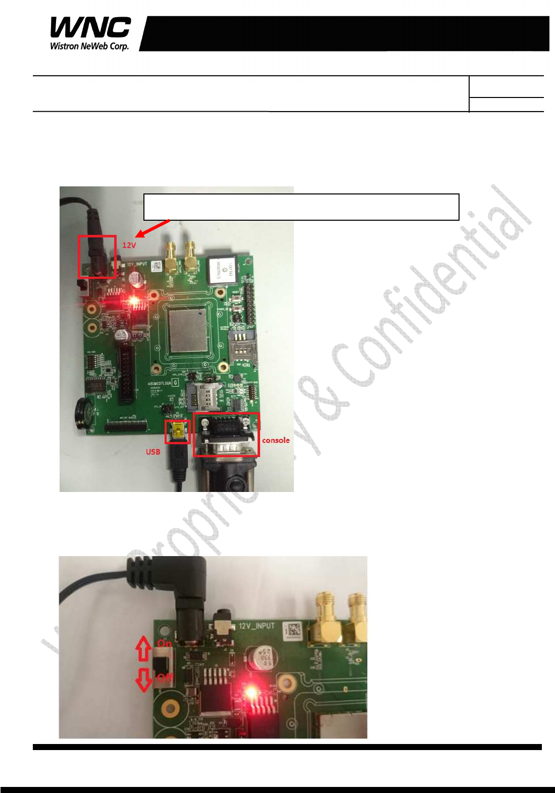
Connection:
Procedures for powering on module:
Step1: Connecting DC12V/5V adapter to the DC jack and sliding the switch to the “ON state”
Supplied by power adapter 5V/1A or 12V/1A( either one)
Subject: UMC-A18Q7 User Manual
REV: 0.1
PAGE 8 OF 21
Wistron Neweb Corporation Proprietary & Confidential
Design Document
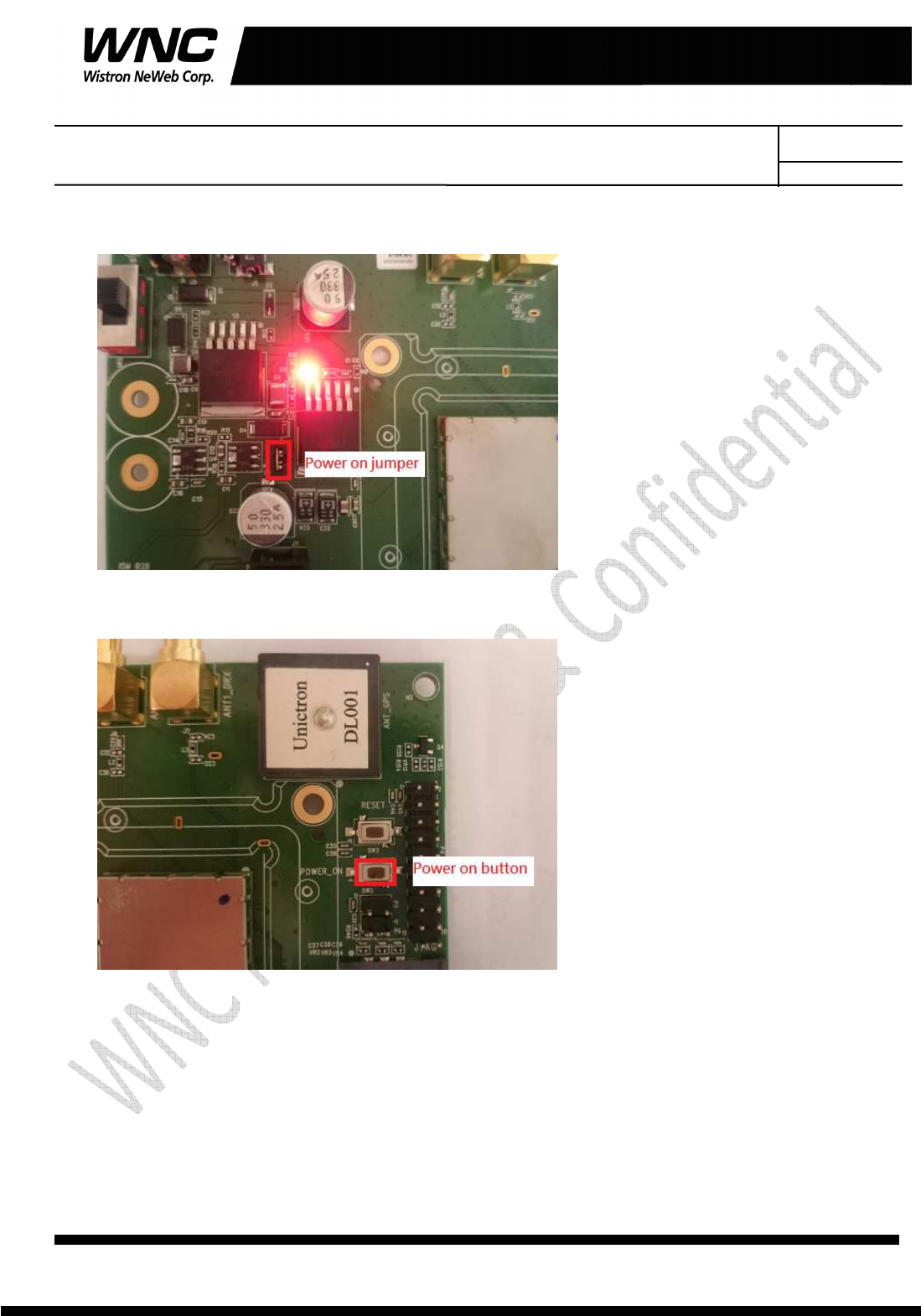
Step 2: Check if power LED lights on, which indicates external power supplies to the interface board
Step3: Press the button of power switch to enable module
Subject: UMC-A18Q7
User Manual
Wistron Neweb Corporation Proprietary & Confidential
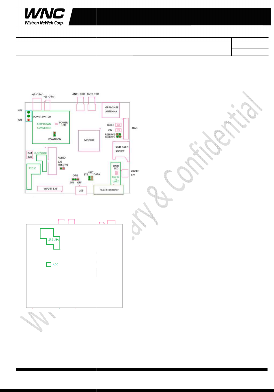
2.3 C
onnectors
The following pictures show the locations for all of
User Manual
Wistron Neweb Corporation Proprietary & Confidential
Design Document
onnectors
and switches
The following pictures show the locations for all of
connectors and switches.
REV: 0.1
PAGE 9 OF 21
Wistron Neweb Corporation Proprietary & Confidential
Design Document
Subject: UMC-A18Q7 User Manual
REV: 0.1
PAGE 10 OF 21
Wistron Neweb Corporation Proprietary & Confidential
Design Document
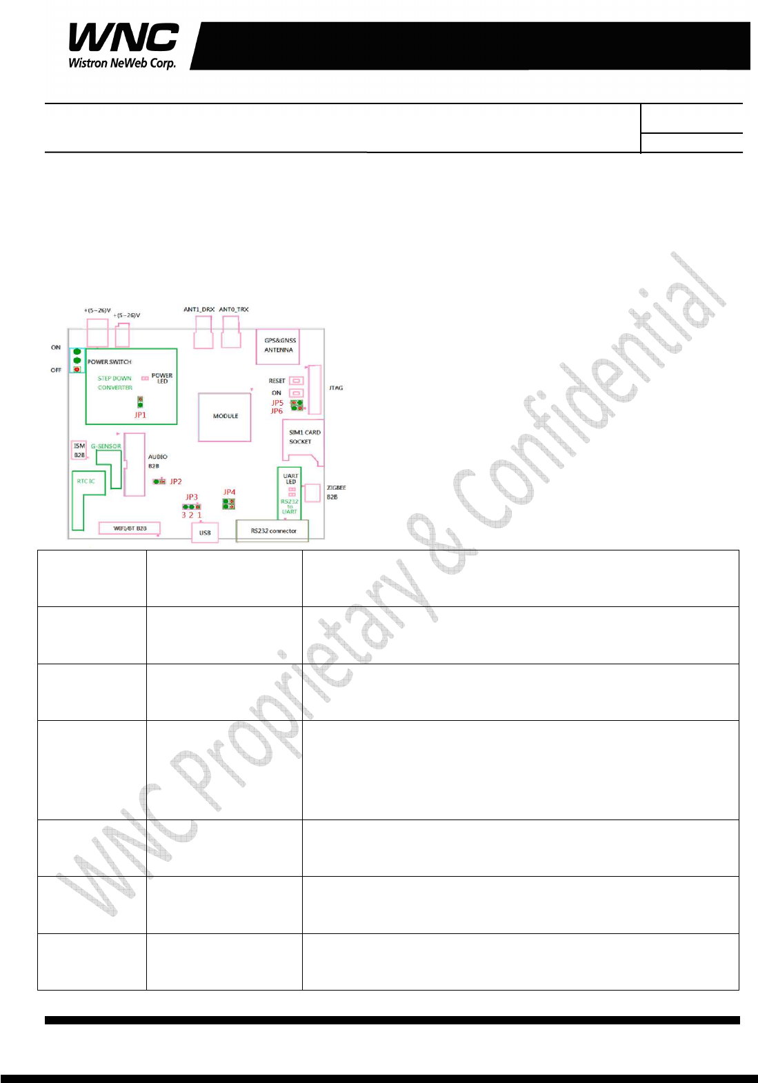
2.4 The configuration by adjusting jumpers
Below figure shows the location of each jumper on developing board. And the configurations for all of
jumpers are addressed in below table. The testers can change it by their own according to different test
conditions.
Jumper Description Comment
JP1 Module Power Provide LTE module power when JP1 had connection.
JP2 Force_USB_BOOT
Force module into USB boot mode when JP2 had connection.
JP3 USB detection Pin12: Enable USB detection,
Pin23: Disable USB detection
JP4 HSIC No used
JP5 Power on LTE module automatic power on when JP5 had connection.
JP6 RESERVE No used
Subject: UMC-A18Q7 User Manual
REV: 0.1
PAGE 11 OF 21
Wistron Neweb Corporation Proprietary & Confidential
Design Document
3. Interfaces
This module offers following interfaces to communicate with module. Except UART console, before those
USB emulated ports could be used, it requires to setup the Qaulcomm’s usb driver into your windows PC
at first.
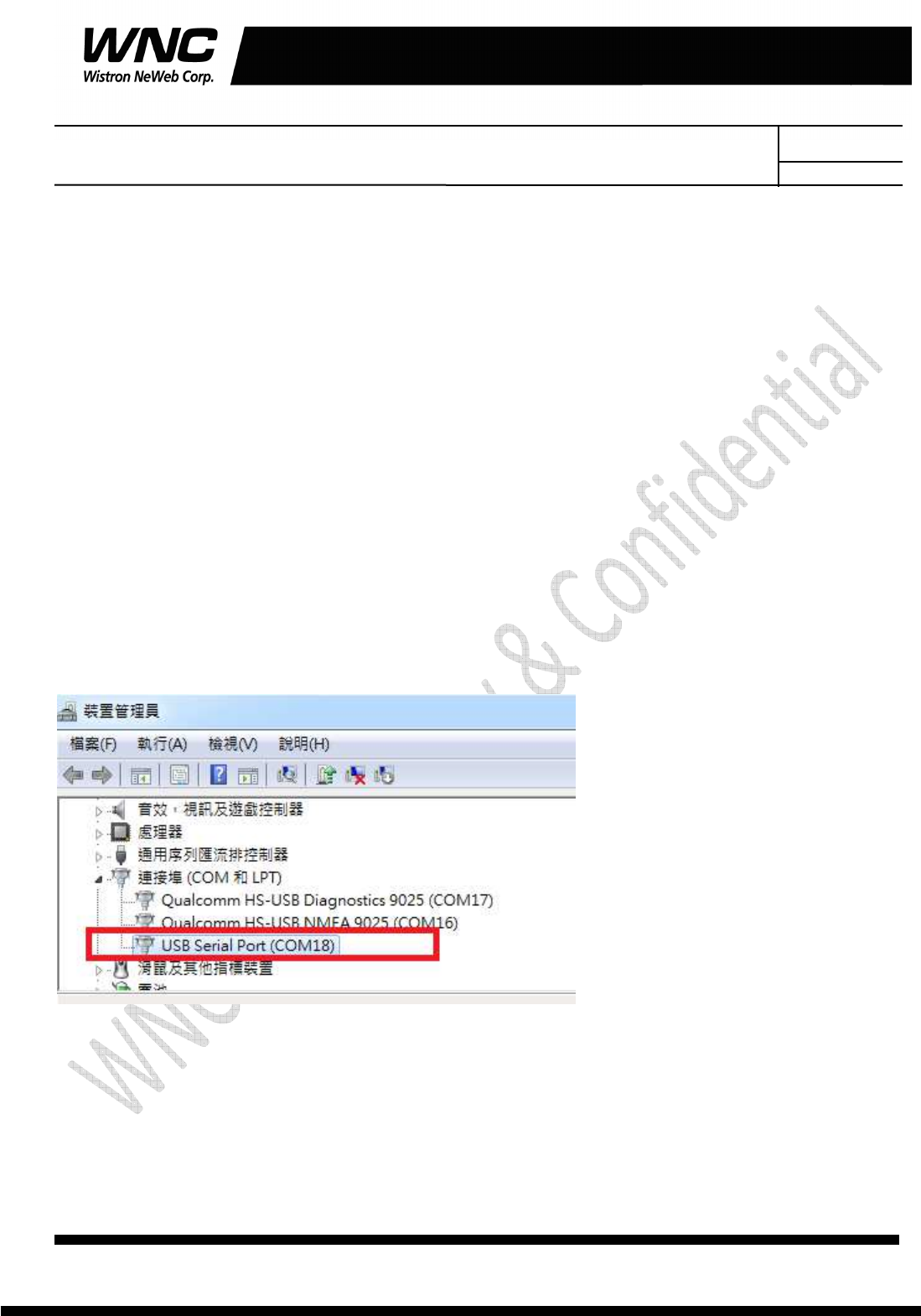
After driver installation is finished, device manager will show below USB emulated COM ports.
3.1 UART port
The UART port is Linux console port, where users could communicate with Linux via shell command. For
current laptops, there is no external COM port connector. Recommend to use an usb-to-uart cable to
connect with the UART port. Then it is required to install the corresponding driver in advance. After
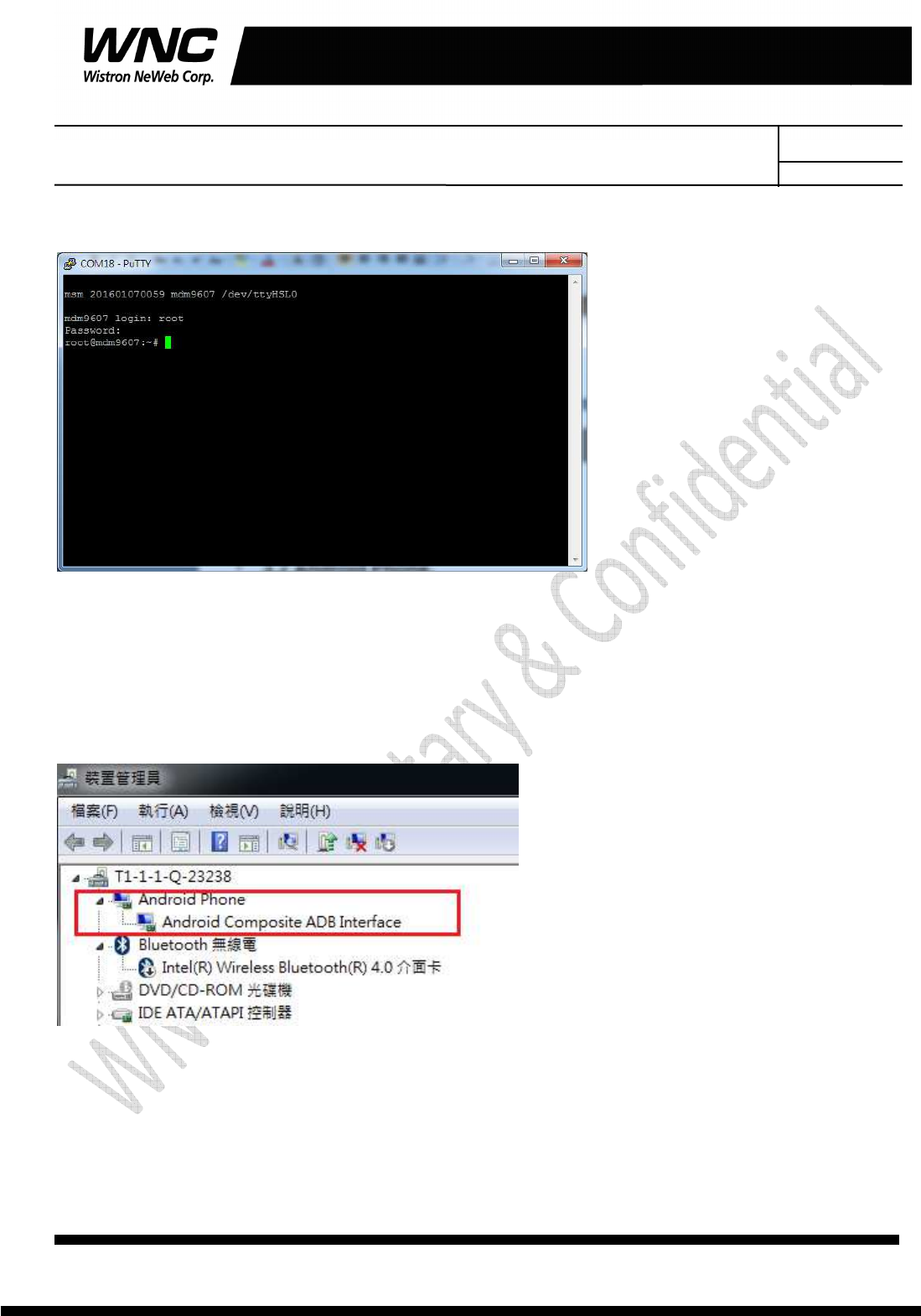
connecting with the cable, it should be able to see the COM port in device manager. For example, COM18
is found for usb-to-uart com port in Windows Device Manager in below figure.
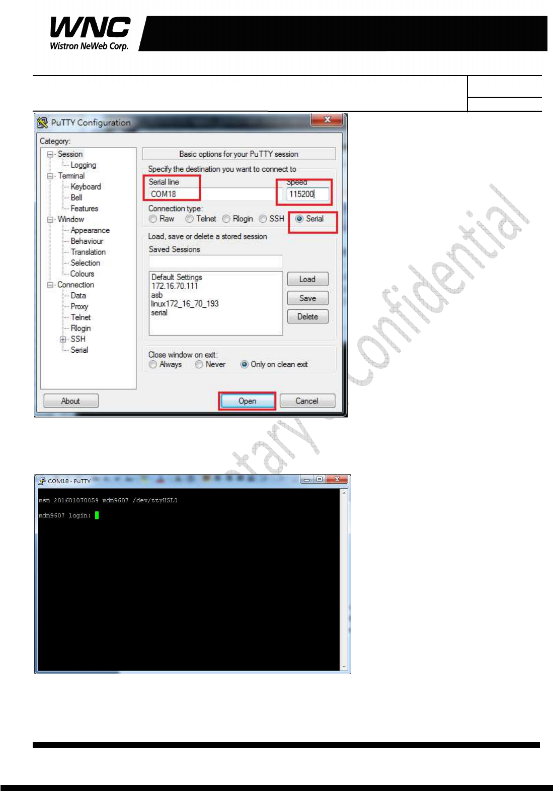
Any terminal emulated tool can be used to communicate with Linux via this port. Putty is an open source
terminal emulator to be an example in following figure.
Subject: UMC-A18Q7 User Manual
REV: 0.1
PAGE 12 OF 21
Wistron Neweb Corporation Proprietary & Confidential
Design Document
After simply configuring speed 115200, terminal will show login prompt. Default login account and
password is shown in below figure.
Subject: UMC-A18Q7 User Manual
REV: 0.1
PAGE 13 OF 21
Wistron Neweb Corporation Proprietary & Confidential
Design Document
Input Login/Password as root/oelinux123.
3.2 Android ADB interface
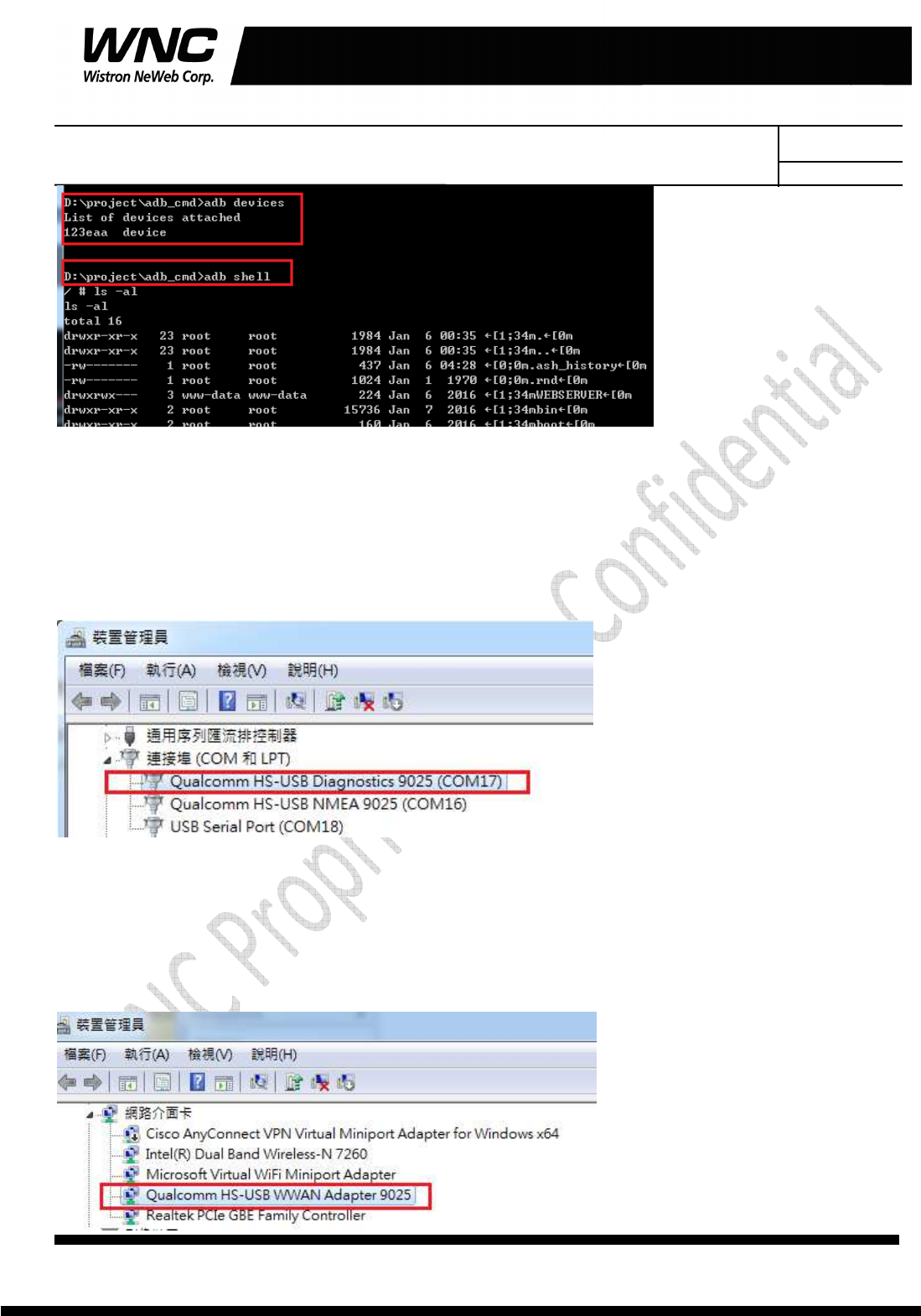
If USB driver is installed successfully, the interface is available as below figure. The functionalities of this
interface like UART port.
It‘s required to install Android USB driver on PC/Windows to use adb tool. Adb tool provides an easy way
for PC side to push Linux applications to run over the module. Command “adb devices” is often the first
command to detect if any module connected with the adb link. And command “adb shell” could start a
Linux shell to operate on module’s Linux system. Please refer to following figure.
Subject: UMC-A18Q7 User Manual
REV: 0.1
PAGE 14 OF 21
Wistron Neweb Corporation Proprietary & Confidential
Design Document
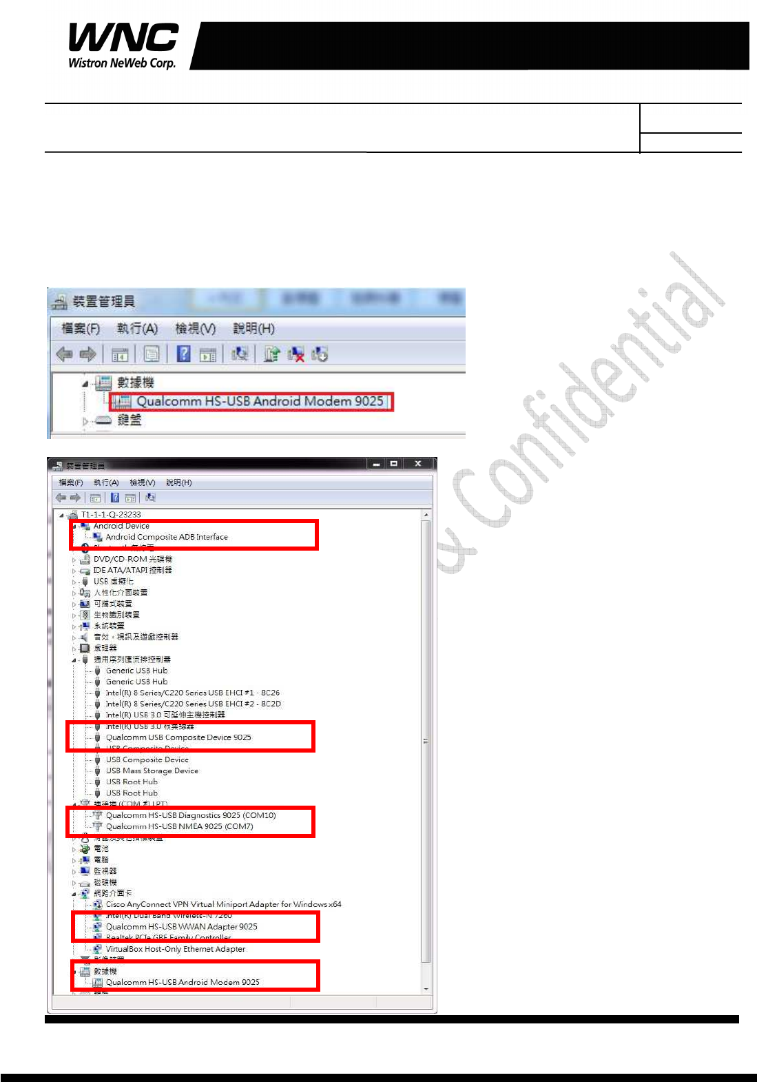
3.3 Qualcomm HS-USB Diagnostics 9025 (COM port)
This port is created for modem debugging purpose and used by Qualcomm PC tools to communicate with
the module. Qualcomm’s tool is protected by Qualcomm License.
3.4 Qualcomm HS-USB WWAN Adapter 9025
This port is created as a virtual network interface which could be used by PC to connect with Internet.
Subject: UMC-A18Q7 User Manual
REV: 0.1
PAGE 15 OF 21
Wistron Neweb Corporation Proprietary & Confidential
Design Document
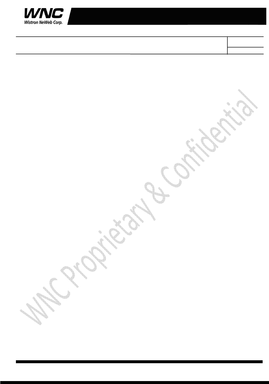
3.5 Qualcomm HS-USB Android Modem 9025
This port is also called as modem port. Users could use PC terminal tool to connect with the port and send
AT commands to control modem directly.
Subject: UMC-A18Q7 User Manual
REV: 0.1
PAGE 16 OF 21
Wistron Neweb Corporation Proprietary & Confidential
Design Document
4. Federal Communication Commission Interference
Statement
This device complies with Part 15 of the FCC Rules. Operation is subject to the following two conditions:
(1) This device may not cause harmful interference, and (2) this device must accept any interference
received, including interference that may cause undesired operation.
This equipment has been tested and found to comply with the limits for a Class B digital device, pursuant
to Part 15 of the FCC Rules. These limits are designed to provide reasonable protection against harmful
interference in a residential installation. This equipment generates, uses and can radiate radio frequency
energy and, if not installed and used in accordance with the instructions, may cause harmful interference
to radio communications. However, there is no guarantee that interference will not occur in a particular
installation. If this equipment does cause harmful interference to radio or television reception, which can
be determined by turning the equipment off and on, the user is encouraged to try to correct the interference
by one of the following measures:
Reorient or relocate the receiving antenna.
Increase the separation between the equipment and receiver.
Connect the equipment into an outlet on a circuit different from that to which the receiver is
connected.
Consult the dealer or an experienced radio technician for help.
FCC Caution:
Any changes or modifications not expressly approved by the party responsible for compliance could
void the user's authority to operate this equipment.
This transmitter must not be co-located or operating in conjunction with any other antenna or
transmitter.
Subject: UMC-A18Q7 User Manual
REV: 0.1
PAGE 17 OF 21
Wistron Neweb Corporation Proprietary & Confidential
Design Document
Radiation Exposure Statement:
This equipment complies with FCC radiation exposure limits set forth for an uncontrolled environment.
This equipment should be installed and operated with minimum distance 20cm between the radiator &
your body.
This device is intended only for OEM integrators under the following conditions:
1) The antenna must be installed such that 20 cm is maintained between the antenna and
users, and the maximum antenna gain allowed for use with this device is +2.0 dBi.
2) The transmitter module may not be co-located with any other transmitter or antenna.
As long as 2 conditions above are met, further transmitter test will not be required. However, the OEM
integrator is still responsible for testing their end-product for any additional compliance requirements
required with this module installed.
IMPORTANT NOTE:
In the event that these conditions cannot be met (for example certain laptop configurations or co-location
with another transmitter), then the FCC authorization is no longer considered valid and the FCC ID cannot
be used on the final product. In these circumstances, the OEM integrator will be responsible for
re-evaluating the end product (including the transmitter) and obtaining a separate FCC authorization.
End Product Labeling:
This transmitter module is authorized only for use in device where the antenna may be installed such that
20 cm may be maintained between the antenna and users. The final end product must be labeled in a
visible area with the following: “Contains FCC ID:
NKR-LMA18Q7
. The grantee's FCC ID can be used
only when all FCC compliance requirements are met.
Manual Information To the End User:
The OEM integrator has to be aware not to provide information to the end user regarding how to install or
remove this RF module in the user’s manual of the end product which integrates this module. The end user
manual shall include all required regulatory information/warning as show in this manual.
Subject: UMC-A18Q7 User Manual
REV: 0.1
PAGE 18 OF 21
Wistron Neweb Corporation Proprietary & Confidential
Design Document
Appendix I
Environmental Setup
1. Windows 7 x64
The environment setup was tested on Windows 7 x64 successfully.
2. Install Android SDK for adb, fastboot and USB driver
To install the Android SDK platform and USB driver components on a Windows
machine:
Go to http://developer.android.com/sdk/win-usb.html.
Follow the instructions for installing the SDK and USB driver.
Right-click My Computer, select Properties > Advanced > Environment Variables, and
set the path to include the“C:\Program Files
(x86)\Android\android-sdk\platform-tools”if you installed Android SDK by using
default path.
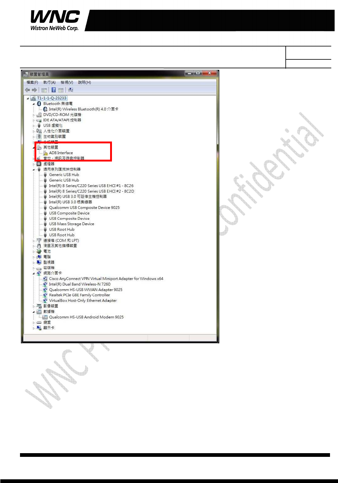
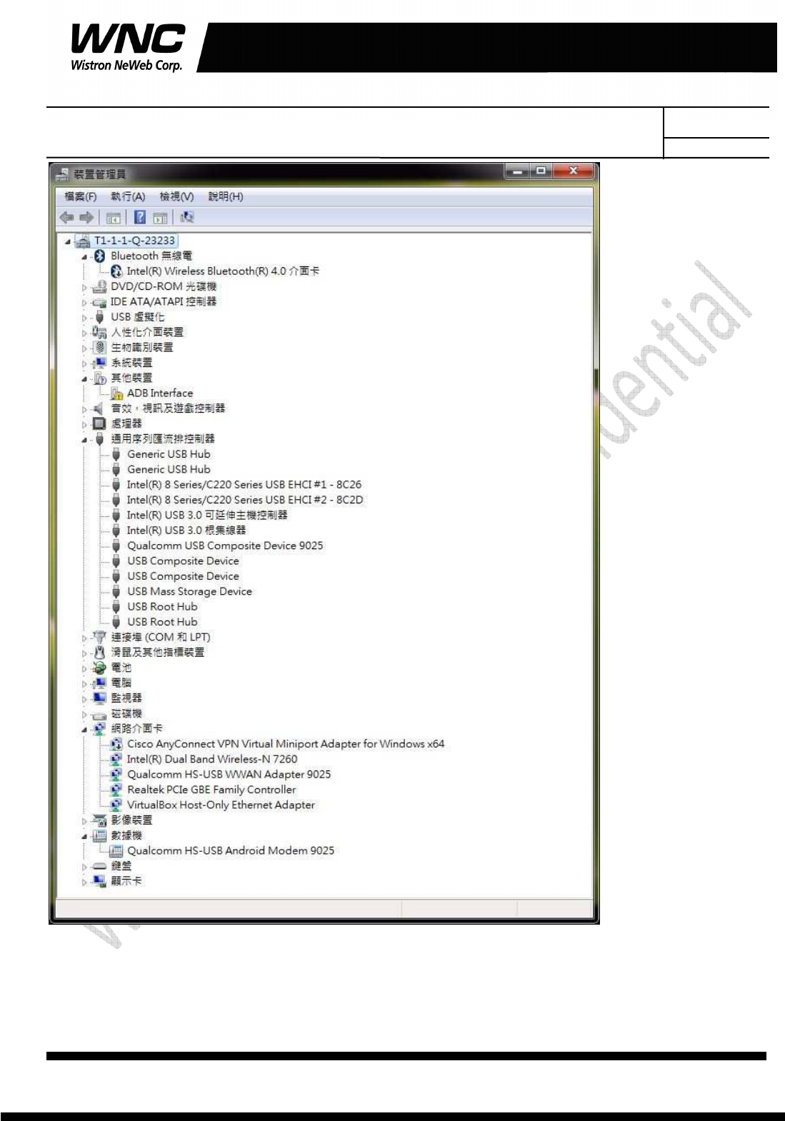
Now the “Windows Devices Managers” looks like the below because there is no QTI
device VPD/PID in default installed USB driver.
Subject: UMC-A18Q7 User Manual
REV: 0.1
PAGE 19 OF 21
Wistron Neweb Corporation Proprietary & Confidential
Design Document
Modify C:\Program Files
(x86)\Android\android-sdk\extras\google\usb_driver\android_winusb.infandroid
_winusb.inf
[Google.NTx86]
;Qualcomm FFA
%SingleAdbInterface% = USB_Install, USB\VID_05C6&PID_9025
%CompositeAdbInterface% = USB_Install, USB\VID_05C6&PID_9025&MI_01
%SingleBootLoaderInterface% = USB_Install, USB\VID_18D1&PID_D00D
Subject: UMC-A18Q7 User Manual
REV: 0.1
PAGE 20 OF 21
Wistron Neweb Corporation Proprietary & Confidential
Design Document
[Google.NTamd64]
;Qualcomm FFA
%SingleAdbInterface% = USB_Install, USB\VID_05C6&PID_9025
%CompositeAdbInterface% = USB_Install, USB\VID_05C6&PID_9025&MI_01
%SingleBootLoaderInterface% = USB_Install, USB\VID_18D1&PID_D00D
In addition, make sure that there are matching entries under the [Strings]
section:
[Strings]
SingleAdbInterface = "Android ADB Interface"
CompositeAdbInterface = "Android Composite ADB Interface"
SingleBootLoaderInterface = "Android Bootloader Interface"
Create a %USERPROFILE%\.android directory if it does not exist
Create/edit the adb_usb.ini file as below contexts
# ANDROID 3RD PARTY USB VENDOR ID LIST -- DO NOT EDIT.
# USE 'android update adb' TO GENERATE.
# 1 USB VENDOR ID PER LINE.
0x05C6
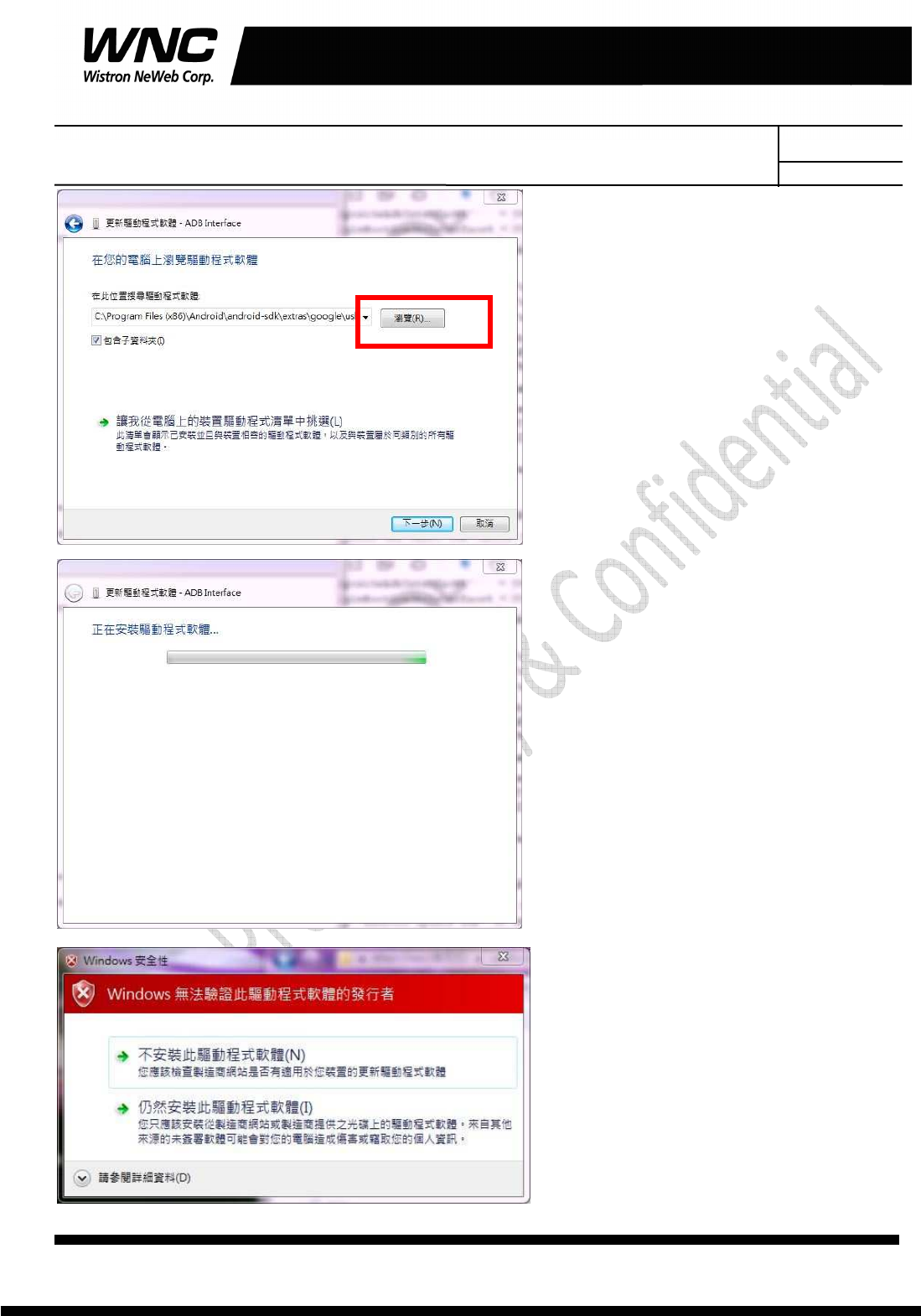
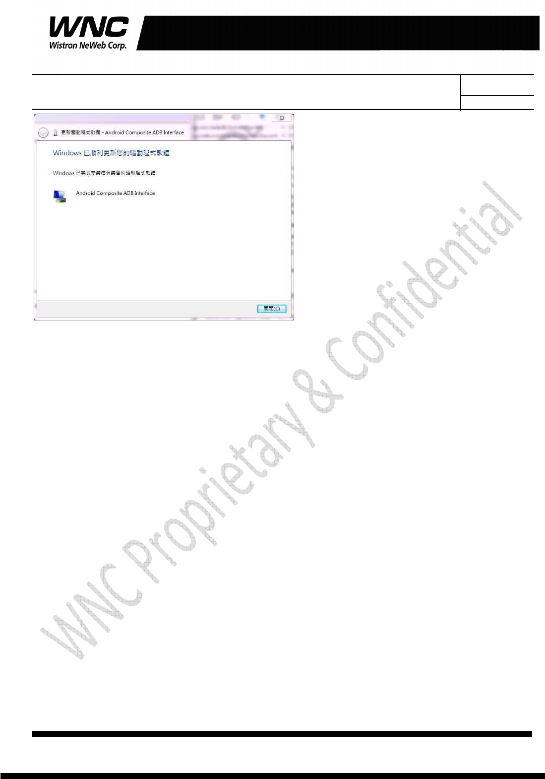
Then open “Windows Device Manager” and click right-button on “ADB Interface” and
then toggle “Upgrade driver”. Then “Refresh driver” will pop up and installation
procedure is shown on following pictures.
Subject: UMC-A18Q7 User Manual
REV: 0.1
PAGE 21 OF 21
Wistron Neweb Corporation Proprietary & Confidential
Design Document
Subject: UMC-A18Q7 User Manual
REV: 0.1
PAGE 22 OF 21
Wistron Neweb Corporation Proprietary & Confidential
Design Document
Subject: UMC-A18Q7 User Manual
REV: 0.1
PAGE 23 OF 21
Wistron Neweb Corporation Proprietary & Confidential
Design Document
3. USB driver
QUD.WIN.1.1 Installer-10037.3 will be needed to be installed for the following ports:
Qualcomm HS-USB Android DIAG
Qualcomm HS-USB Android Modem
Qualcomm HS-USB Android GPS (NMEA)
Qualcomm Wireless HS-USB Ethernet Adapter on a Windows 7 OS