Wistron NeWeb LMZBCARD ZBCARD User Manual 1
Wistron NeWeb Corporation ZBCARD 1
User Manual

Subject: UMC-ZBCARD User Manual REV: 5.0
PAGE 1 OF 14
Wistron Neweb Corporation Proprietary & Confidential
Design Document
UMC-ZBCARD User Manual
Subject: UMC-ZBCARD User Manual REV: 5.0
PAGE 2 OF 14
Wistron Neweb Corporation Proprietary & Confidential
Design Document
Revision History
Issue Date
Version
Description
2018/11/14
1.0
Initial Issued
2018/11/29
2.0
Initial Issued
2018/11/29
3.0
Add Warring message
2018/12/17
4.0
Add part 15 FCC rule
2018/12/19
5.0
Modify part 15C information

Subject: UMC-ZBCARD User Manual REV: 5.0
PAGE 3 OF 14
Wistron Neweb Corporation Proprietary & Confidential
Design Document
Contents
1. Introduction ............................................................................................................................................ 4
2. Test Setup Configuration ....................................................................................................................... 5
2.1 Power Supply and Debug Console Connection ......................................................................... 6
i. UMC-ZBCARD ..................................................................................................................... 6
ii. UMC-A21LG2-R ................................................................................................................... 7
iii. Interface board ....................................................................................................................... 8
iv. Connection between UMC-ZBCARD, UMC-A21LG2-R and interface board ..................... 9
2.2 Zigbee Connection ....................................................................................................................11
2.3 Hardware Component Introduction ......................................................................................... 12
2.4 Install Qualcomm USB driver ................................................................................................ 13
2.5 Confirm the Qualcomm device .............................................................................................. 13
3. Zigbee test ........................................................................................................................................... 15
3.1 Firmware version of Application .......................................................................................... 15
3.2 ZigBee Test Command ............................................................................................................ 16
4. Interfaces .............................................................................................................................................. 17
4.1 Qualcomm HS-USB MDM Diagnostics 90B2 (COM port) .................................................... 17
4.2 Qualcomm HS-USB WWAN Adapter 90B2 ........................................................................... 18
4.3 Qualcomm HS-USB Modem 90B2 ......................................................................................... 18
5. Appendix I ........................................................................................................................................... 20

Subject: UMC-ZBCARD User Manual REV: 5.0
PAGE 4 OF 14
Wistron Neweb Corporation Proprietary & Confidential
Design Document
1. Introduction
This User Manual of UMC-ZBCARD is to describe how to use the following sections
for lab test by specific qualified engineers or technicians. Furthermore, this SMCC (Smart
Metering Communication Card) is NOT intended for commercial use but designed as part
of Smart Meter product which mainly provides 4G LTE WAN access. The UMC-ZBCARD
is optional for SMCC. For the procedure of SMCC installation and set-up for testing and
operating, the information is described as well in the following description.
This device complies with Part 15 of the FCC Rules.
Operation is subject to the following two conditions: (1) this device may not cause
harmful interference, and (2) this device must accept any interference received, including
interference that may cause undesired operation.
For Class B digital device or peripheral or cordless phone (15.105) This equipment has been
tested and found to comply with the limits for a Class B digital device, pursuant to Part 15
of the FCC Rules. These limits are designed to provide reasonable protection against harmful
interference in a residential installation. This equipment generates, uses and can radiate
radio frequency energy and, if not installed and used in accordance with the instructions,
may cause harmful interference to radio communications.
However, there is no guarantee that interference will not occur in a particular
installation. If this equipment does cause harmful interference to radio or television reception,
which can be determined by turning the equipment off and on, the user is encouraged to try
to correct the interference by one or more of the following measures:
◆ Reorient or relocate the receiving antenna.
◆ Increase the separation between the equipment and receiver.
◆ Connect the equipment into an outlet on a circuit different from that to which the
receiver is needed.
◆ Consult the dealer or an experienced radio/TV technician for help.
Subject: UMC-ZBCARD User Manual REV: 5.0
PAGE 5 OF 14
Wistron Neweb Corporation Proprietary & Confidential
Design Document
-This is module approval and thus OEM integrator statement and contained ID must be
provided.
This device is intended only for OEM integrators under the following conditions:
1) For Meter installations (the end device install with ZB card), the antenna must be
installed such that 20 cm is maintained between the antenna and users.
2) The transmitter module may not be co-located with any other transmitter or antenna. As
long as the 2 conditions above are met, further transmitter testing will not be
required. However, the OEM integrator is still responsible for testing their end-product for
any additional compliance requirements required with this module installed (for example,
add more device interface etc.).
IMPORTANT NOTE: In the event that these conditions cannot be met (for example
certain meter configurations or co-location with another transmitter), then the FCC
authorization is no longer considered valid and the FCC ID cannot be used on the final
product. In these circumstances, the OEM integrator will be responsible for re-evaluating
the end product (including the transmitter) and obtaining a separate FCC authorization.
End Product labeling this transmitter module is authorized only for use in devices
where the antenna may be installed such that 20 cm may be maintained between the antenna
and users (For meter device.. The final end product must be labeled in a visible area with
the following: "Contains TX FCC ID: {NKR-LMZBCARD}".
The ZigBee antenna type is PIFA. ZigBee Antenna Peak Gain is 0.64 ~ 1.02 dBi
Warning:
Radiation Exposure Statement
This module complies with FCC radiation exposure limits set forth for an uncontrolled
environment. This module should be installed and operated with minimum distance of
20cm between radiator and human body.
Any changes or modifications not expressly approved by the party responsible for
compliance could void the user’s authority to operate the device.
Subject: UMC-ZBCARD User Manual REV: 5.0
PAGE 6 OF 14
Wistron Neweb Corporation Proprietary & Confidential
Design Document
2. Test Setup Configuration
2.1 Power Supply and Debug Console Connection
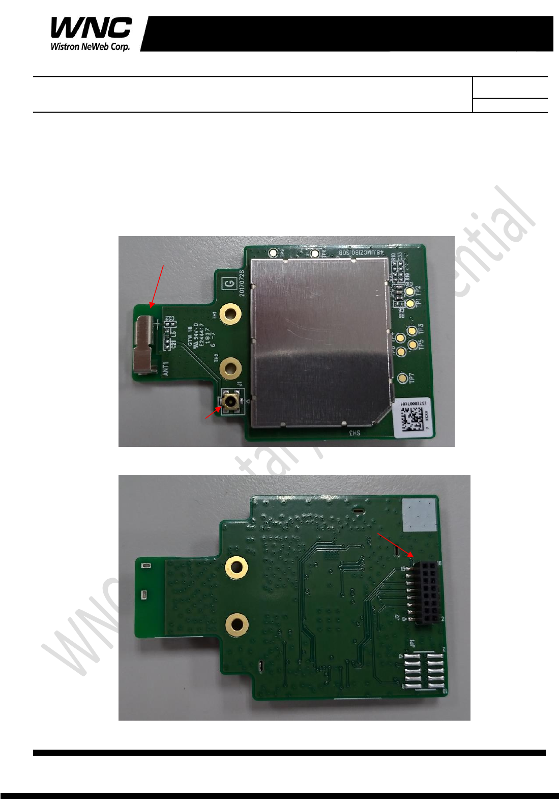
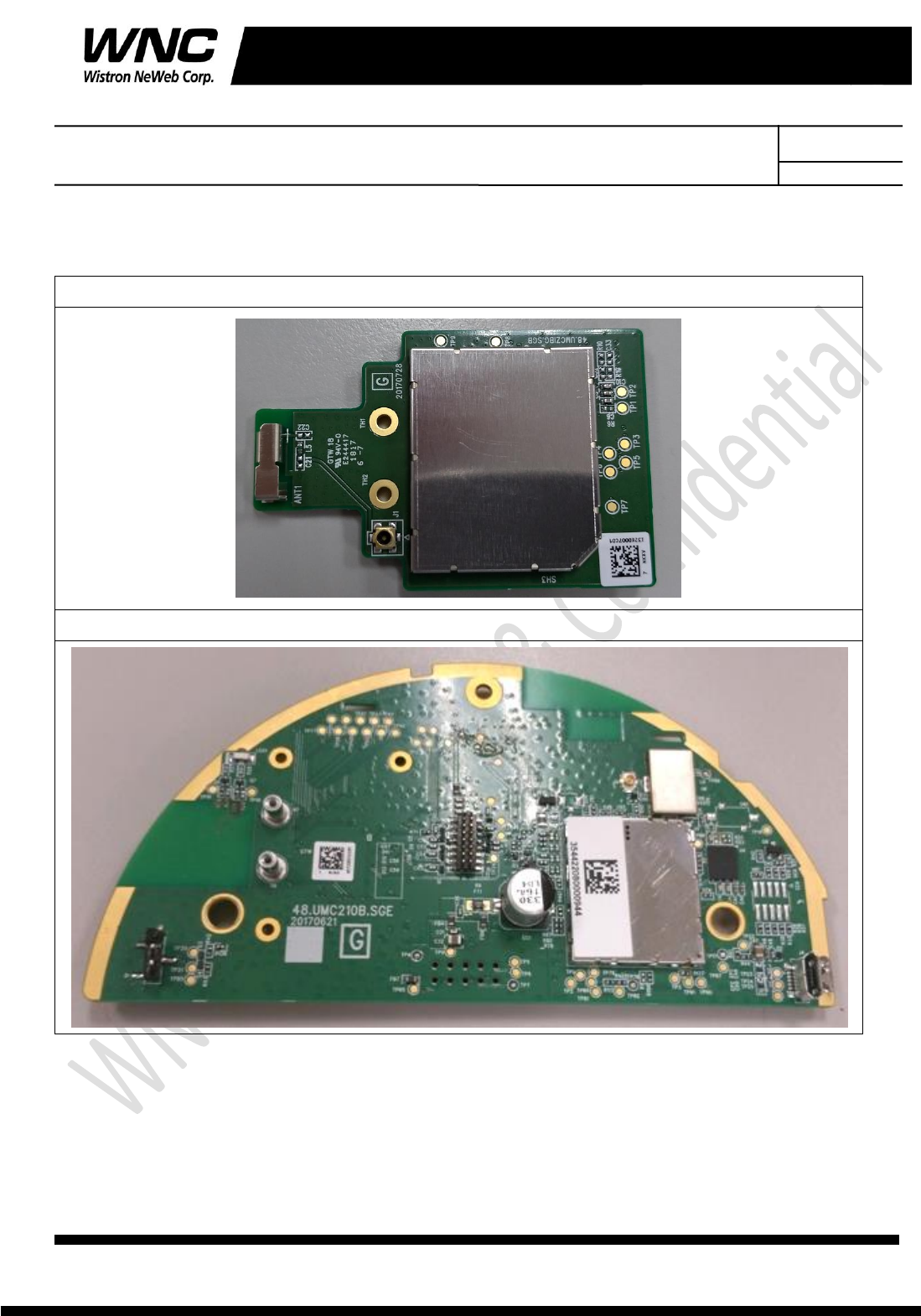
i. UMC-ZBCARD
Top view
Bottom view
Zigbee antenna
Zigbee RF connector
Board to board connector

Subject: UMC-ZBCARD User Manual REV: 5.0
PAGE 7 OF 14
Wistron Neweb Corporation Proprietary & Confidential
Design Document
ii. UMC-A21LG2-R
Top view
Bottom view
Make sure to connect the Zigbee card
Debug USB port
UMC-ZBCARD connector
LTE module
Subject: UMC-ZBCARD User Manual REV: 5.0
PAGE 8 OF 14
Wistron Neweb Corporation Proprietary & Confidential
Design Document
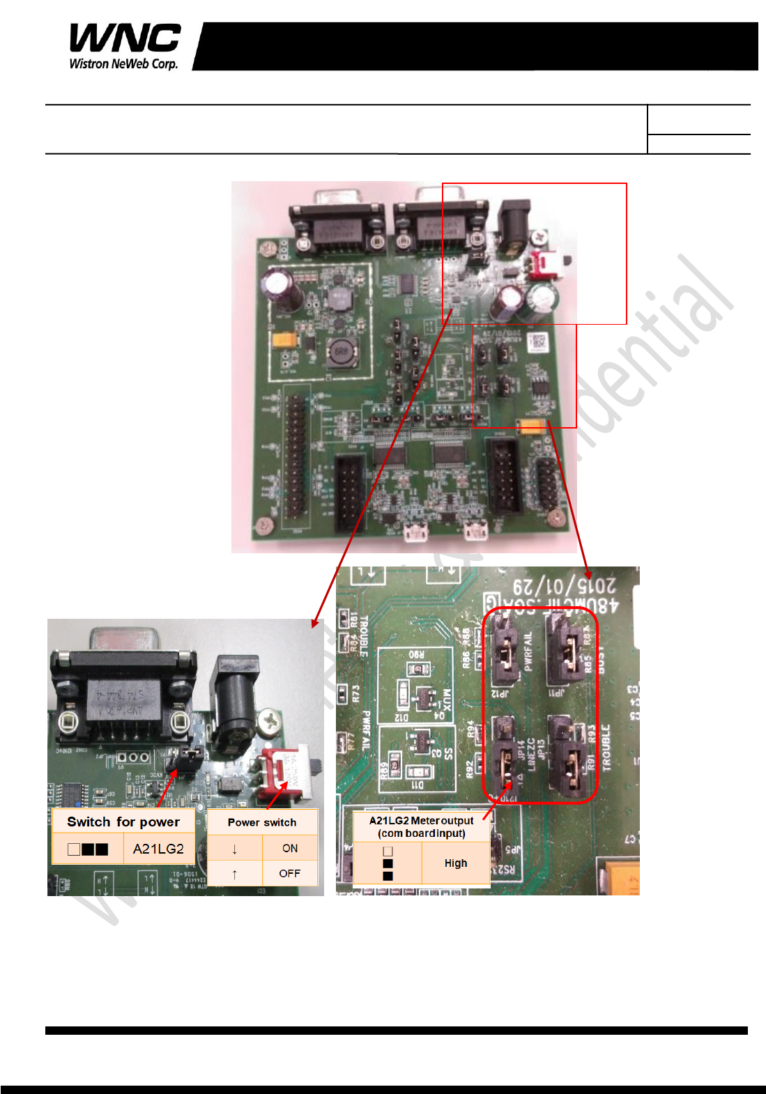
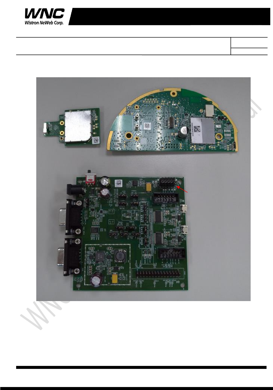
iii. Interface board
Make sure the jumpers are in right position.
Subject: UMC-ZBCARD User Manual REV: 5.0
PAGE 9 OF 14
Wistron Neweb Corporation Proprietary & Confidential
Design Document
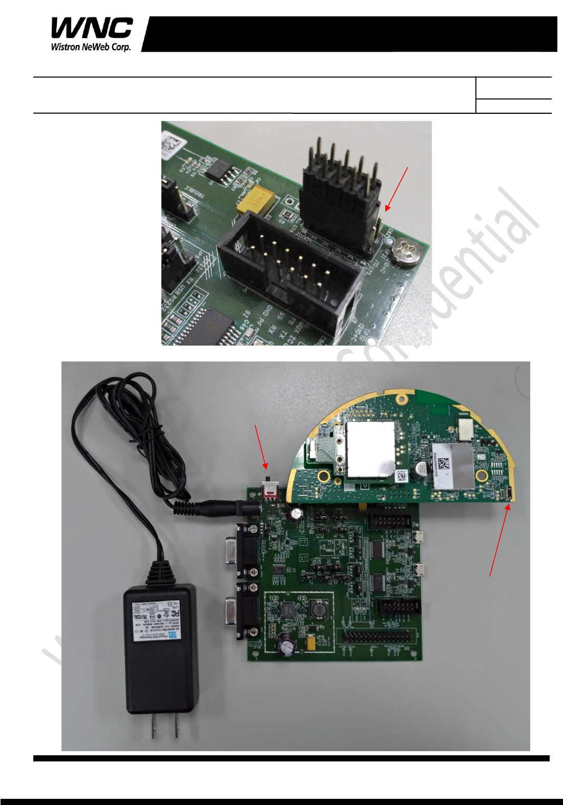
iv. Connection between UMC-ZBCARD, UMC-A21LG2-R and interface
board
10 pin Connect to interface board
Don’t care last 2 pin
UMC-A21LG2-R
OFF ON
UMC-ZBCARD
Subject: UMC-ZBCARD User Manual REV: 5.0
PAGE 10 OF 14
Wistron Neweb Corporation Proprietary & Confidential
Design Document
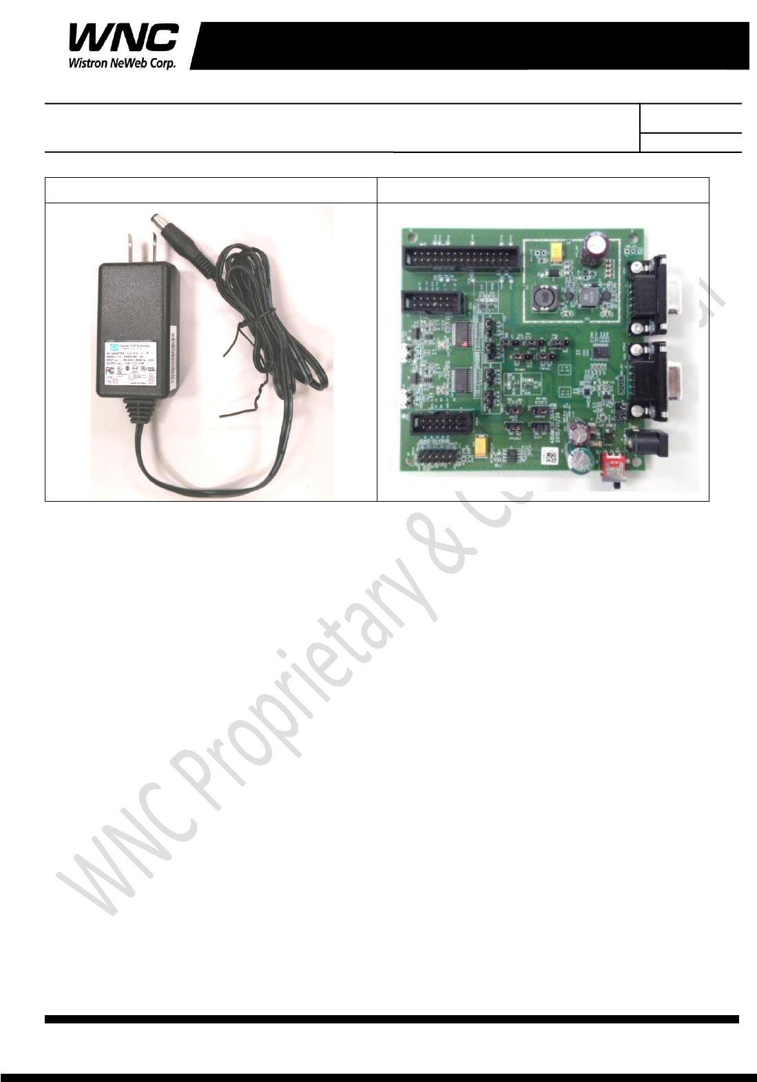
AC-DC 5V Adaptor
Interface Board
UMC-A21LG2 with UMC-ZBCARD
USB Debug Port Console
Power switch
10 pin Connect to interface board
Don’t care last 2 pin
Subject: UMC-ZBCARD User Manual REV: 5.0
PAGE 11 OF 14
Wistron Neweb Corporation Proprietary & Confidential
Design Document
Power on Sequence:
I. Connect UMC-A21LG2-R with UMC-ZBCARD to interface board
II. Attach AC-DC Adaptor & USB Debug Port Cable
III. Turn on by the power switch
IV. Wait for 20 seconds when system ready
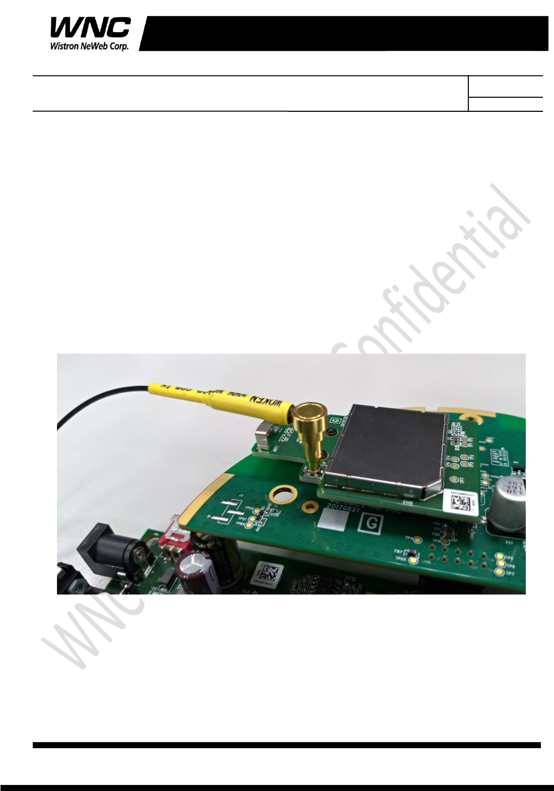
2.2 Zigbee Connection
Connect to Zigbee RF connector for conducted test
Subject: UMC-ZBCARD User Manual REV: 5.0
PAGE 12 OF 14
Wistron Neweb Corporation Proprietary & Confidential
Design Document
2.3 Hardware Component Introduction
UMC-ZBCARD
UMC-A21LG2-R
Subject: UMC-ZBCARD User Manual REV: 5.0
PAGE 13 OF 14
Wistron Neweb Corporation Proprietary & Confidential
Design Document
AC-DC 5V Adaptor
Interface Board
2.4 Install Qualcomm USB driver
Install the Qualcomm USB driver & ADB driver
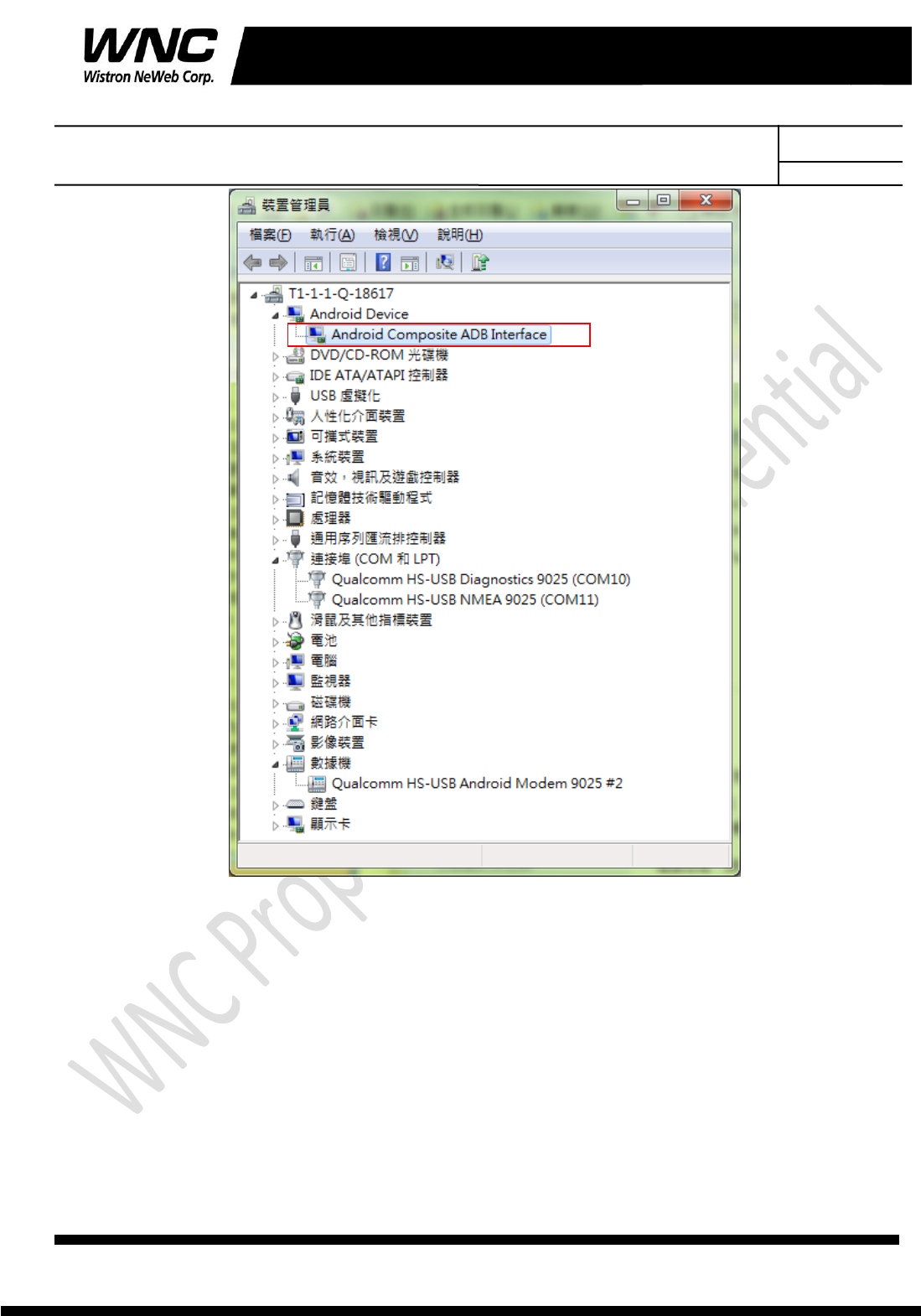
2.5 Confirm the Qualcomm device
Confirm the Android Device “Android Comosite ADB interface”
Subject: UMC-ZBCARD User Manual REV: 5.0
PAGE 14 OF 14
Wistron Neweb Corporation Proprietary & Confidential
Design Document
Subject: UMC-ZBCARD User Manual REV: 5.0
PAGE 15 OF 14
Wistron Neweb Corporation Proprietary & Confidential
Design Document
3. Zigbee test
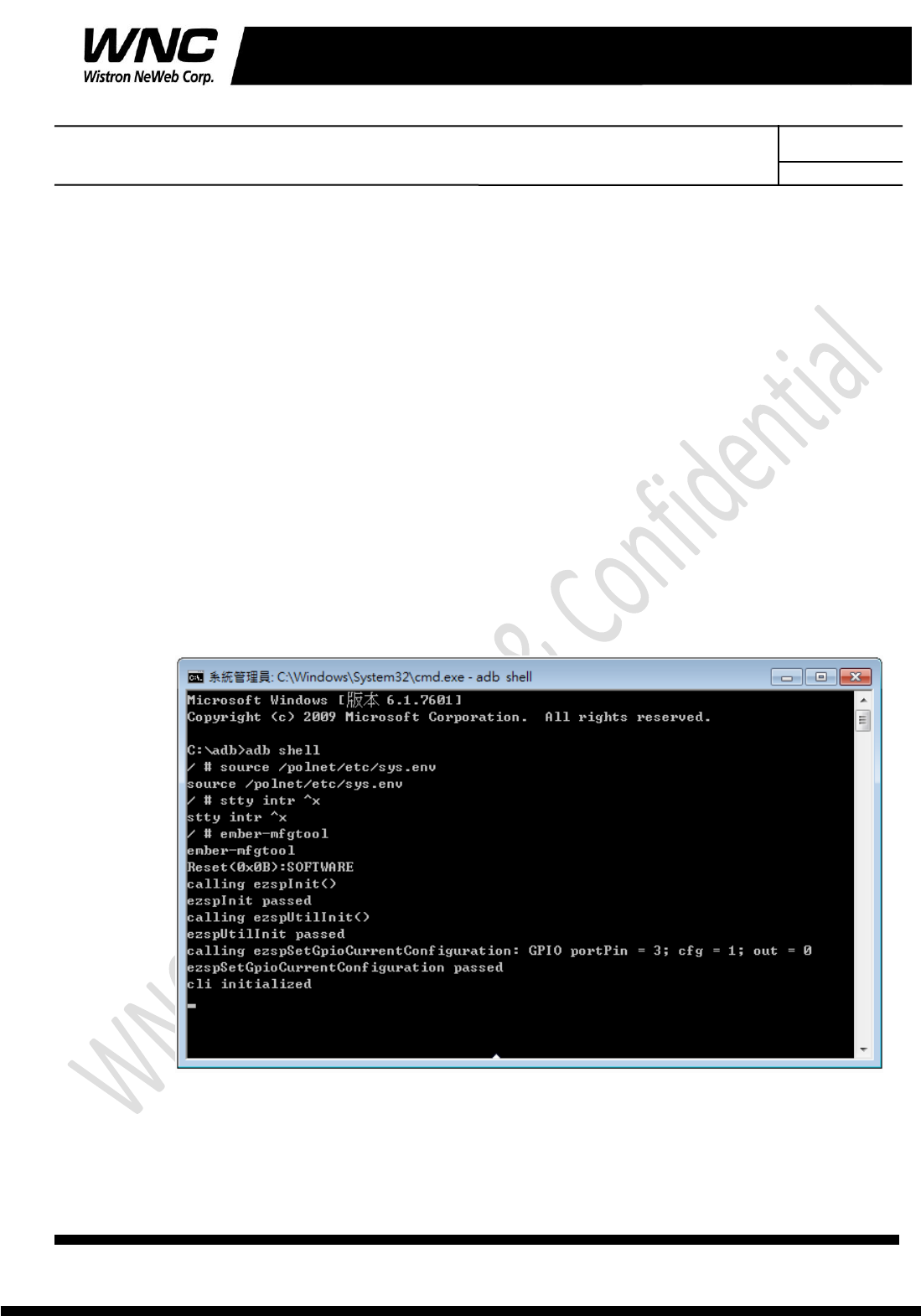
3.1 Firmware version of Application
Command in Command Prompt:
adb shell
Command in adb shell:
source /polnet/etc/sys.env
stty intr ^x
Subject: UMC-ZBCARD User Manual REV: 5.0
PAGE 16 OF 14
Wistron Neweb Corporation Proprietary & Confidential
Design Document
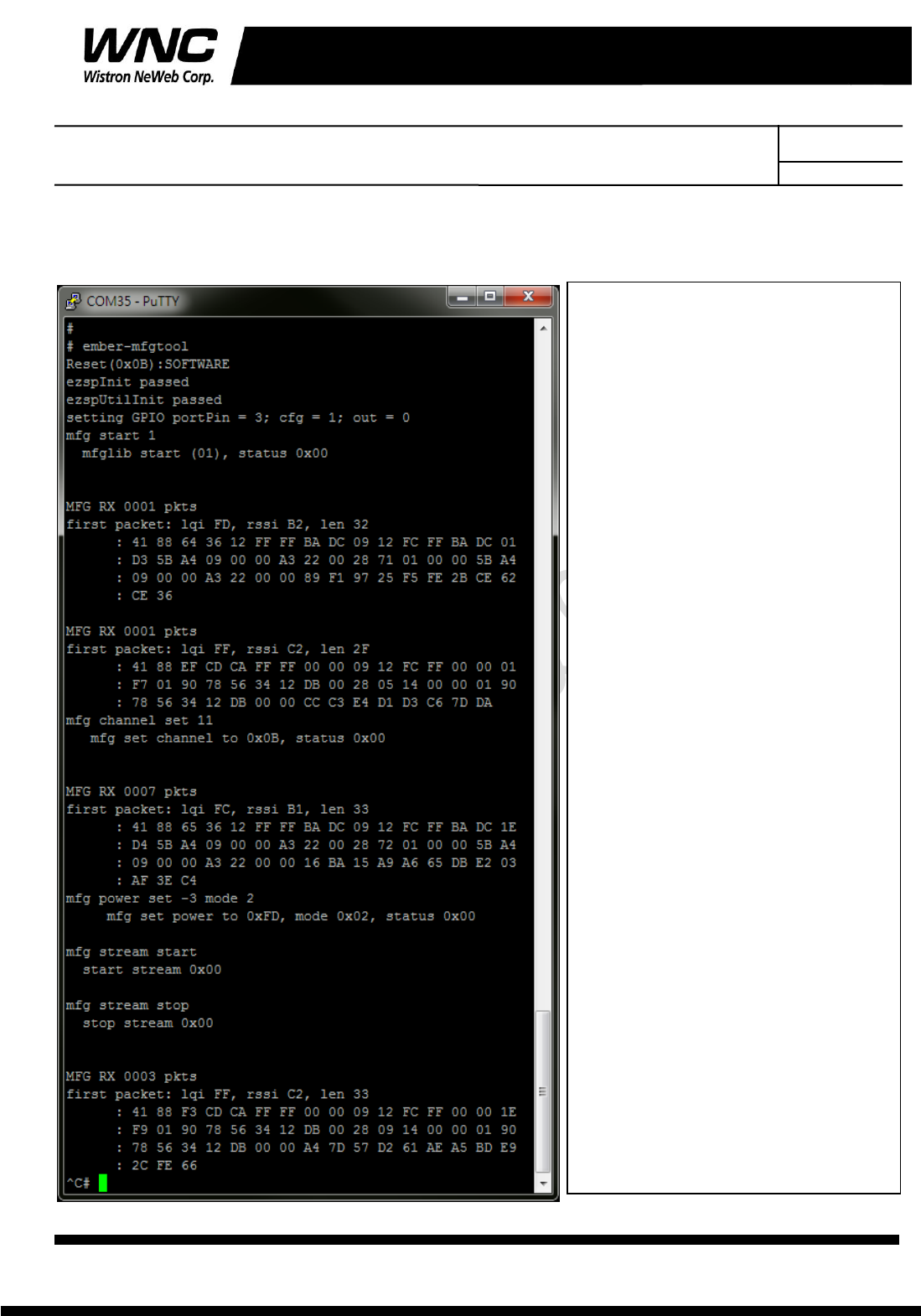
3.2 ZigBee Test Command
Enter Zigbee control mode:
ember-mfgtool
Set mfg start:
mfg start 1
Freq. channel setting:
mfg channel set 11
Channel Low : 11 -> CH11
Channel Mid : 18 -> CH18
Channel High : 25 -> CH25
Power level/mode setting:
mfg power set -3 mode 2
Single tone output:
mfg tone start
Single tone output stop:
mfg tone stop
Modulation signal output:
mfg stream start
Modulation signal output stop :
mfg stream stop
Exit:
<Ctrl>+<X>
<Enter>
Subject: UMC-ZBCARD User Manual REV: 5.0
PAGE 17 OF 14
Wistron Neweb Corporation Proprietary & Confidential
Design Document
4. Interfaces
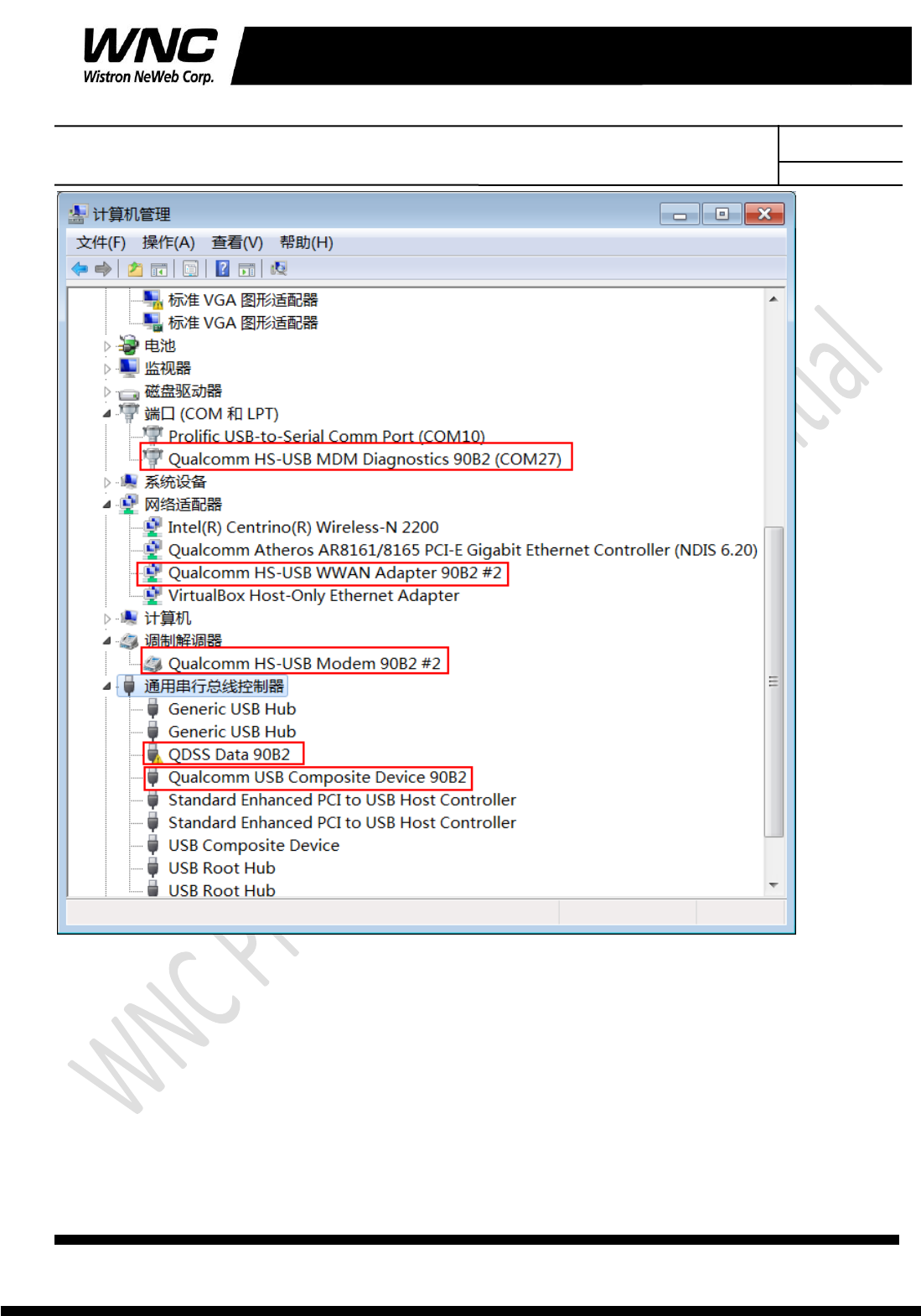
This SMCC offers following interfaces to communicate with module. Before using USB
emulated ports, it requires to install the Qualcomm’s USB driver on your windows PC in
advance. After driver installation is finished, device manager will show below USB emulated
COM ports.
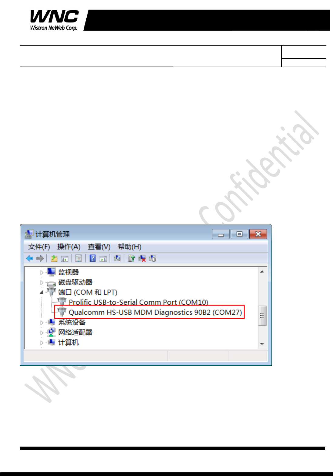
4.1 Qualcomm HS-USB MDM Diagnostics 90B2 (COM port)
This port is created for modem debugging purpose and used by Qualcomm PC tools to
communicate with the module. Qualcomm’s tool is protected by Qualcomm License.
Subject: UMC-ZBCARD User Manual REV: 5.0
PAGE 18 OF 14
Wistron Neweb Corporation Proprietary & Confidential
Design Document
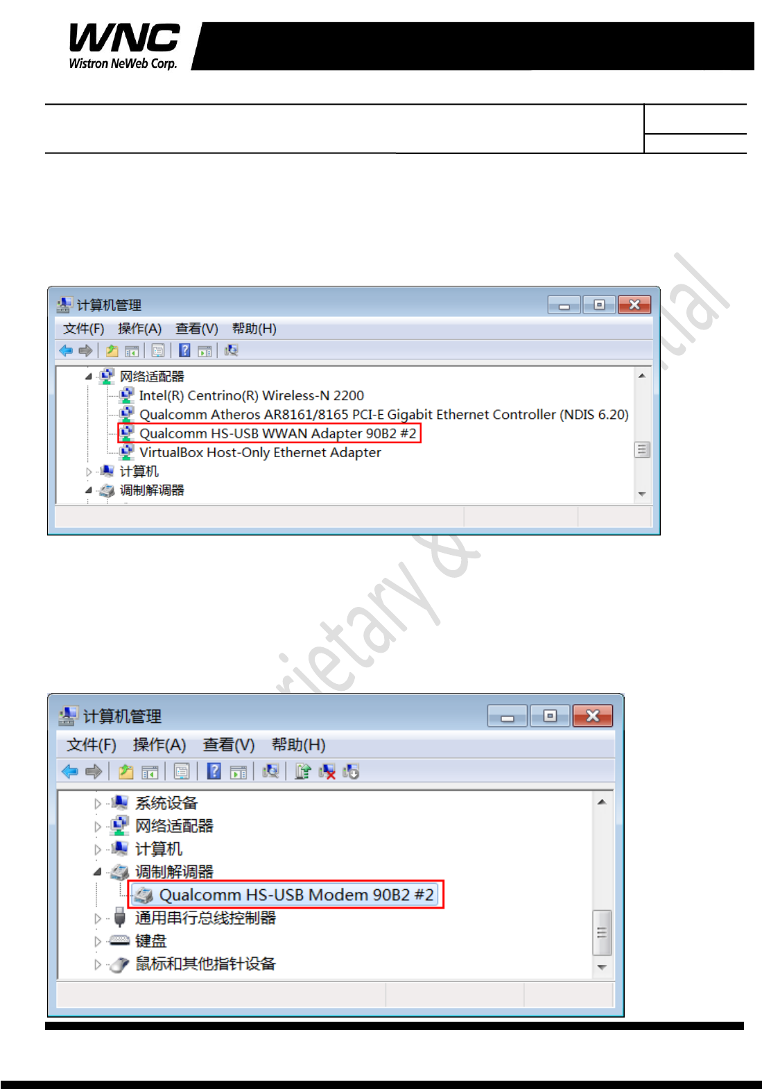
4.2 Qualcomm HS-USB WWAN Adapter 90B2
This port is created as a virtual network interface which could be used by PC to connect with
Internet.
4.3 Qualcomm HS-USB Modem 90B2
This port is also called as modem port. Testers could use PC terminal tool to connect with
the port and send AT commands to control modem directly.
Subject: UMC-ZBCARD User Manual REV: 5.0
PAGE 19 OF 14
Wistron Neweb Corporation Proprietary & Confidential
Design Document

Subject: UMC-ZBCARD User Manual REV: 5.0
PAGE 20 OF 14
Wistron Neweb Corporation Proprietary & Confidential
Design Document
5. Appendix I
Environmental Setup
1. Windows 7 x64
The environment setup was tested on Windows 7 x64 successfully.
2. USB driver
QUD.WIN.1.1 Installer will be needed to be installed for the following ports:
Qualcomm HS-USB MDM Diagnostics 90B2
Qualcomm HS-USB MDM WWAN Adapter 90B2
Qualcomm USB Composite Device 90B2
QDSS Data 90B2
Qualcomm HS-USB Modem 90B2
3. ADB driver
http://adbdriver.com/