Wistron NeWeb RM1 Mini-PCI Card User Manual manual
Wistron NeWeb Corporation Mini-PCI Card manual
Users Manual
WLAN b+g mini-PCI Module
RM1
OEM Installation Manual
(The module is sold only to the OEM integrators & the
manual is valid only for the OEM manufactures)
Version: 1.0
June 2004

1
Copyright Statement
No part of this publication may be reproduced, stored in a retrieval system, or
transmitted in any form or by any means, whether electronic, mechanical,
photocopying, recording or otherwise without the prior writing of the publisher.
Windows™ 98SE/2000/ME/XP are trademarks of Microsoft® Corp.
Pentium is trademark of Intel.
All copyright reserved.

2
Federal Communication Commission Interference Statement
This equipment has been tested and found to comply with the limits for a Class
B digital device, pursuant to Part 15 of the FCC Rules. These limits are
designed to provide reasonable protection against harmful interference in a
residential installation. This equipment generates, uses and can radiate radio
frequency energy and, if not installed and used in accordance with
the instructions, may cause harmful interference to radio communications.
However, there is no guarantee that interference will not occur in a particular
installation. If this equipment does cause harmful interference to radio or
television reception, which can be determined by turning the equipment off and
on, the user is encouraged to try to correct the interference by one of the
following measures:
- Reorient or relocate the receiving antenna.
- Increase the separation between the equipment and receiver.
- Connect the equipment into an outlet on a circuit different from that to which
the receiver is connected.
- Consult the dealer or an experienced radio/TV technician for help.
FCC Caution: To assure continued compliance, (example - use only shielded
interface cables when connecting to computer or peripheral devices) any
changes or modifications not expressly approved by the party responsible for
compliance could void the user's authority to operate this equipment.
This device complies with Part 15 of the FCC Rules. Operation is subject to the
following two conditions:
(1) This device may not cause harmful interference, and
(2) This device must accept any interference received, including interference
that may cause undesired operation.
IMPORTANT NOTE:
This module is restricted to mobile configuration. To comply with FCC RF exposure
compliance requirements, the antenna used for this transmitter must be installed to
provide a separation distance of at least 20 cm from all persons and must not be
co-located or operating in conjunction with any other antenna or transmitter. This
transmitter module must not be co-located or operating in conjunction with any
other antenna or transmitter

3
Table of Contents
Table of Contents .................................3
1. Introduction .....................................4
1.1 The WLAN 802.11b+g mini-PCI Module 4
1.2 Hardware Installation & Antenna Information 4
*Caution !!...........................................6
(1). This module cannot be bound in a tablet computer for RF exposure issues. (See label 1)6
(3). This module must be labeled with FCC ID. (See label 2) 6
(4). If the FCC ID is not visible when the module is installed inside another device, then the outside of
device must also display a label referring to the enclosed module. The exterior label can be “ Contains
Transmitter Module FCC ID:NKRRM1 ” or similar wording. (See label 3) 7
2. Features ..........................................8
3. Hardware Connections.......................9
4. Remove the Module ......................... 11
5. Basic Configuration of your Access Point12
5.1 Logging On .............................. 13
5.2 Setup Wizard............................ 13
l 5.2.1 SETTING UP LOCAL TIME ZONE AND DATE/TIME 13
l 5.2.2 DEVICE IP SETTINGS 13
l 5.2.2 DEVICE IP SETTINGS 14
l 5.2.3 CONFIGURE YOUR WIRELESS LAN CONNECTION 15
l 5.2.4 FINISH SETUP WIZARD AND SAVE YOUR SETTINGS 16
4
1. Introduction
1.1 The WLAN 802.11b+g mini-PCI Module
Thank you for purchasing the WLAN b+g mini-PCI Module that provides the easiest
way to wireless networking. This User Manual contains detailed instructions in the
operation of this product. Please keep this manual for future reference.
SYSTEM REQUIREMENTS
l Microsoft® Win™2000/ME/98 Second Edition/XP
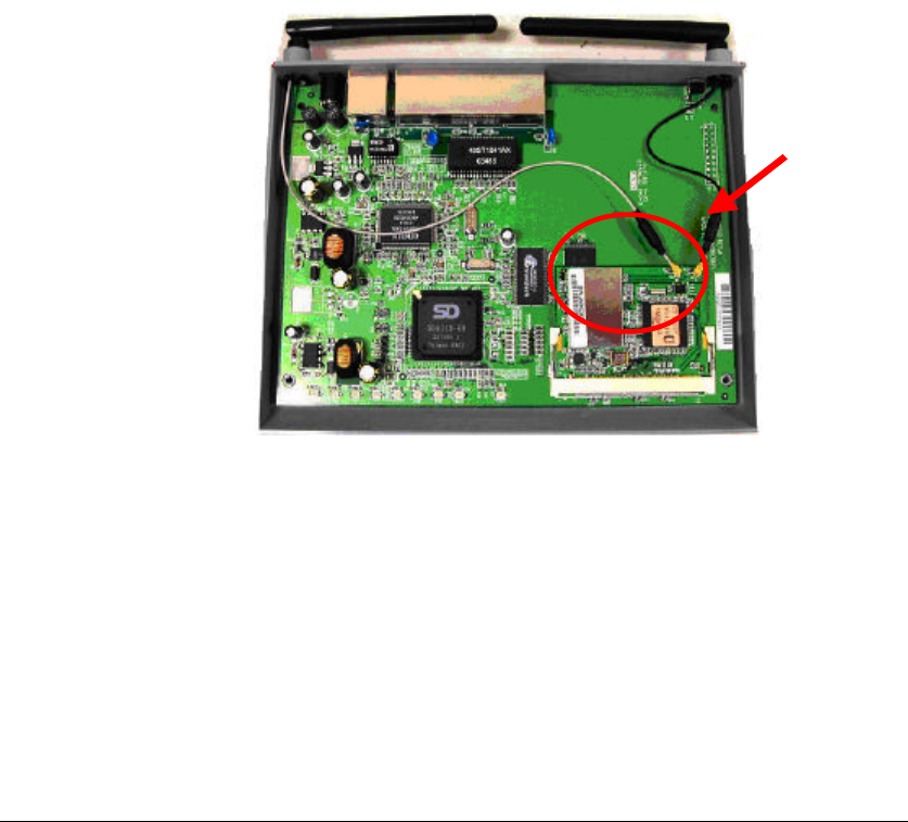
1.2 Hardware Installation & Antenna Information
l MODULE IS INSTALLED IN THE ROUTER. (SEE THE FOLLOWING DIAGRAMS).
5
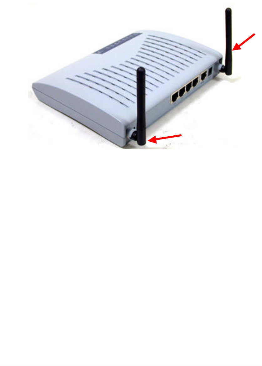
l Antennas are embedded in the two sides (see the two antennas shown
below)
Only the antenna type listed below can be used:
(1) Vendor WanShih Electronic CO. Model: Wss002
Important Note:
This module is restricted to mobile configuration. The antennas of module
should be installed and operated with minimum distance 20cm between the
radiator and all persons. This transmitter must not be co-located or operating in
conjunction with any other antenna or transmitter.
The module is for OEM installation only and can not be sold to end user directly.
Main
Aux
6
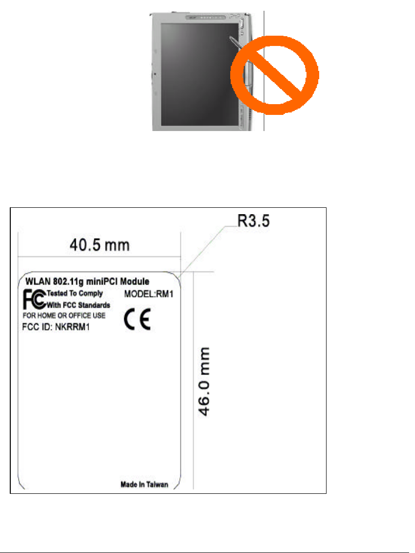
*Caution !!
(1). This module cannot be bound in a tablet
computer for RF exposure issues. (See label 1)
(3). This module must be labeled with FCC ID.
(See label 2)
Label 2
Label 1

7
(4). If the FCC ID is not visible when the module
is installed inside another device, then the
outside of device must also display a label
referring to the enclosed module. The exterior
label can be “ Contains Transmitter Module FCC
ID:NKRRM1 ” or similar wording. (See label 3)
Please put Label 3 to the enclosure of end product to
note the end user.
Label 3

8
2. Features
n Easy integration into OEM devices
n Wireless connects more PCs for Home & Office
n Supports up to 128-bit WEP, WPA, AES and CCX
n Cost effective solution
9
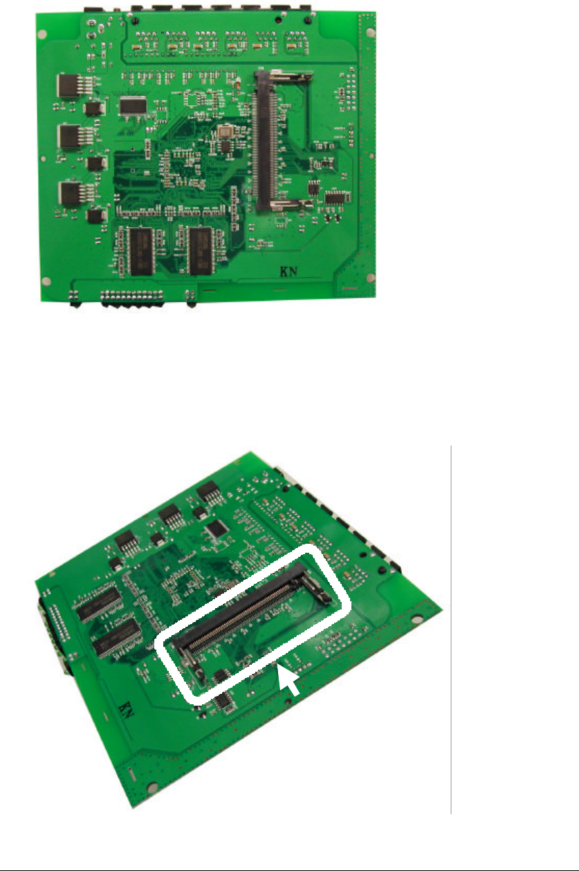
3. Hardware Connections
1. Have your Access Point Prototyping Board ready.
2. Find the mini-PCI slot on the Prototyping Board.
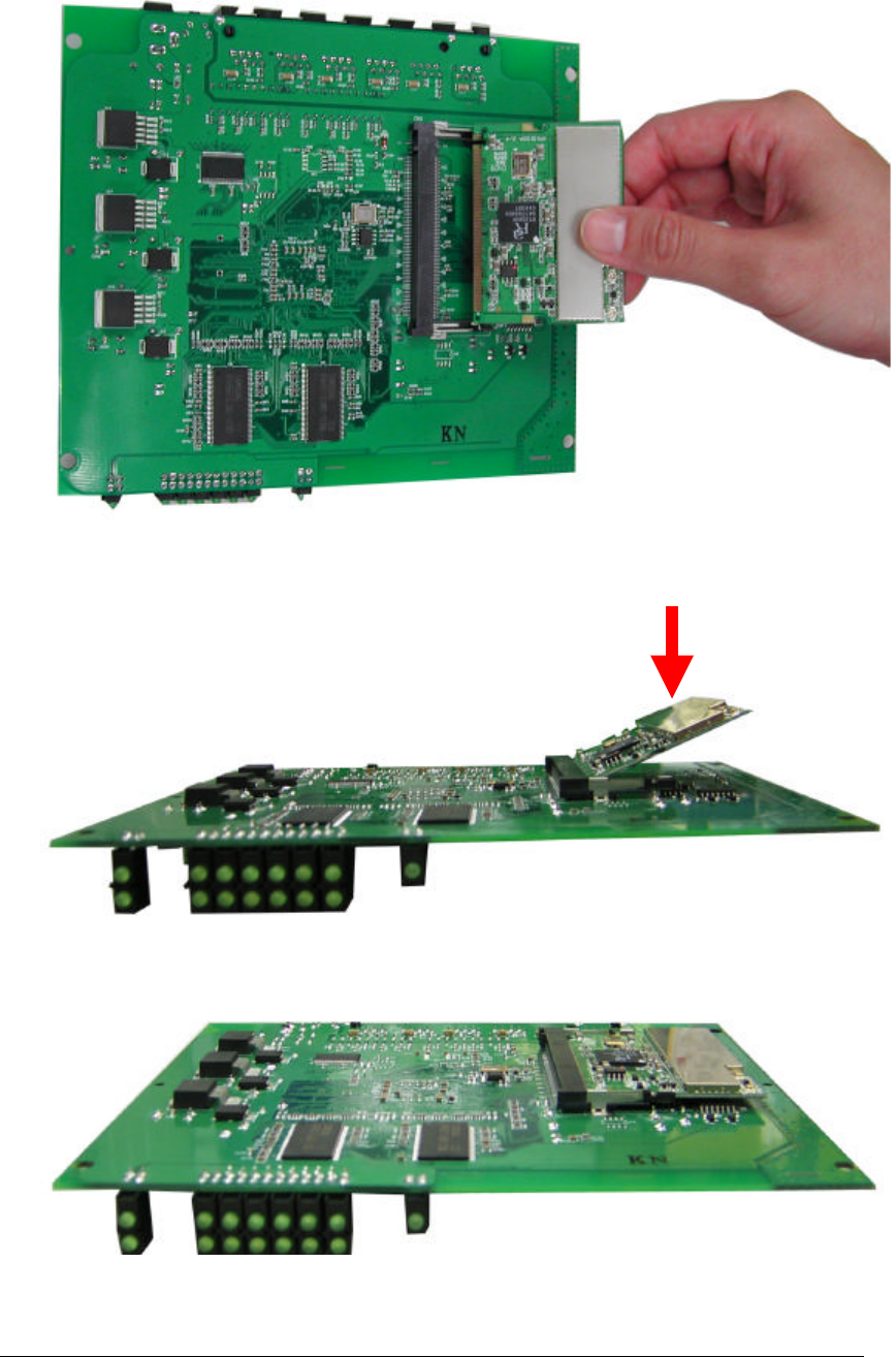
10
3. Insert the WLAN 802.11g mini-PCI Module into the mini-PCI slot on the
Prototyping Board.
4. Press down the Module until it is secured with the two latches on the Board.
5. Hardware Installation is completed.
11
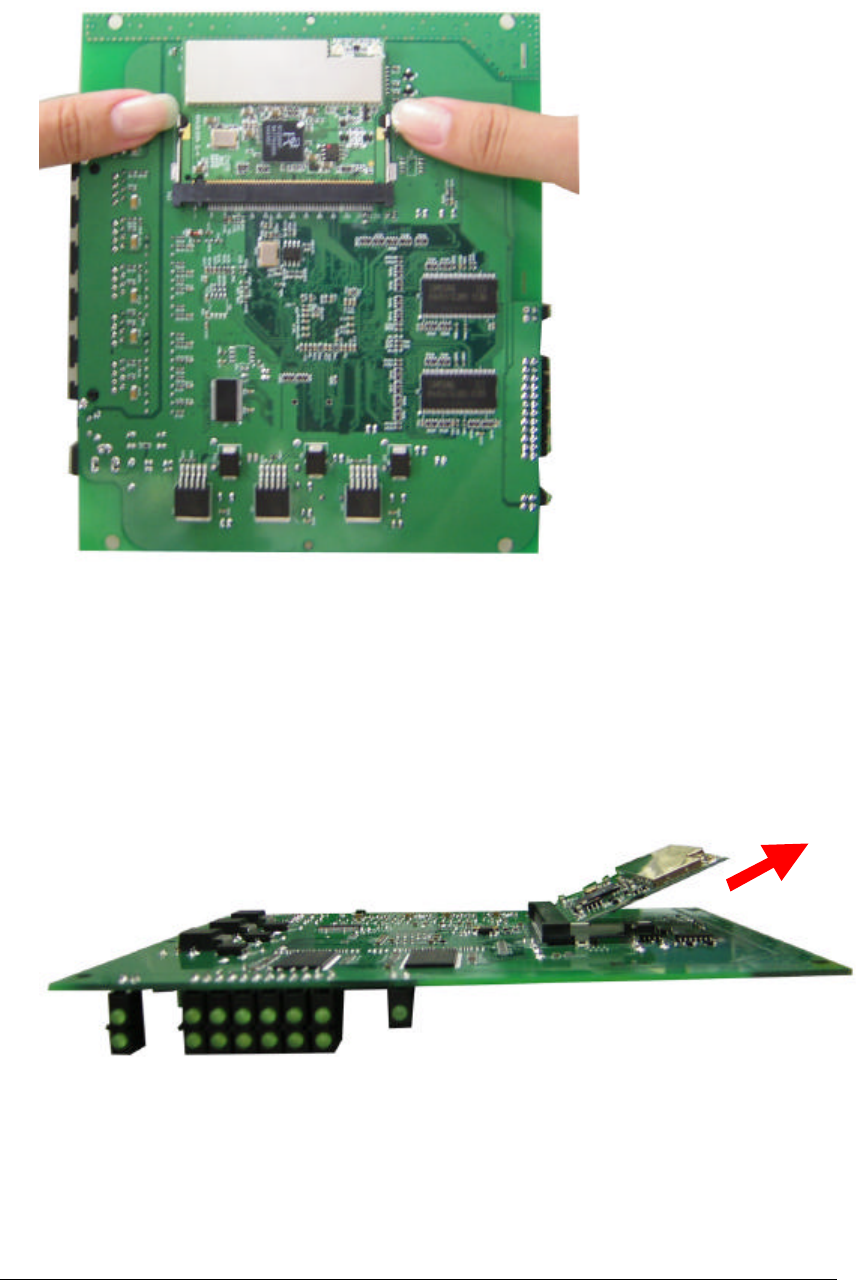
4. Remove the Module
1. Release the two latches by gently remove them aside.
2. The module pops up. Remove the Module.
12
5. Basic Configuration of your Access Point
This section gives you an example of the general basic configuration procedure for
your Access Point. It describes how to set up the Access Point for Infrastructure BSS
operation, and the configuration of the local LAN environment.
Although the Command Line Interface (CLI) may also be used to configure the
Access Point, the example we are using here is the browser-based configuration
mechanism.
Suppose the Access Point is designed that all basic configuration may be effected
through the a standard Web browser such as Internet Explorer.
From a PC or a Wireless client, enter the IP address of the Access Point as the URL in
your browser.
Note: The IP address of your PC must be in the same IP subnet as the Access
Point.
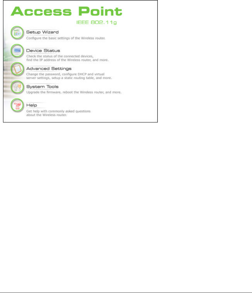
The Home Page of the Access Point screen will appear, with its main menu displayed
on the upper-side of the screen. The main menu includes the following choices: Setup
Wizard, Device Status, System Tools, Advanced Settings and Help choices, which can
be used to navigate to other menus.
13
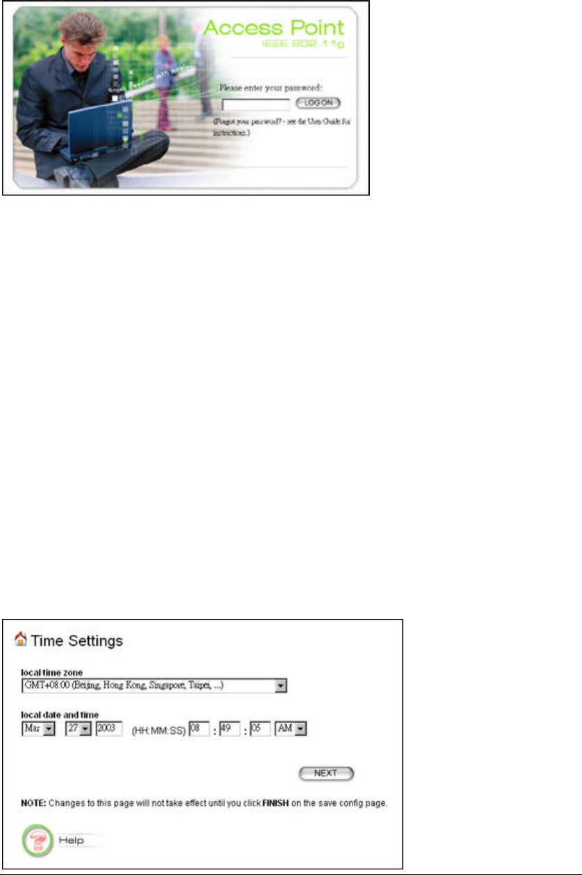
5.1 Logging On
If you attempt to access a configuration item from the browser menu, an administrator
login screen will appear, prompting you to enter the password in order to log on.
If you are logging on for the first time, you should use the factory default setting
“password”. The password is always displayed as a string of asterisks (“*”). Clicking
the LOG ON button will begin the configuration session.
5.2 Setup Wizard
The Setup Wizard will guide you through a series of configuration screens to set up
the basic functionality of the device. After you finish configuring these screens and
press the “finish” button on the last screen, all your configuration modifications will
take effect.
5.2.1 SETTING UP LOCAL TIME ZONE AND DATE/TIME
After logging in, the time settings page appears. The AP time is automatically set to
the local time of the management PC the first time a connection is made. To modify
the AP’s clock, modify the appropriate fields, and click “NEXT”.
14
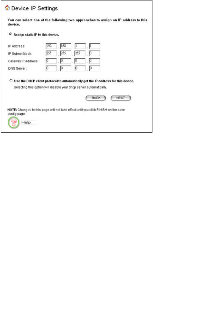
5.2.2 DEVICE IP SETTINGS
The Device IP setting screen allows you to configure the IP address and subnet of the
AP on the LAN. Although you can rely on a DHCP server to assign an IP address to
the Access Point automatically, it is recommended that you configure a static IP
address manually in most applications.
If you choose to assign the IP address manually, check the button that says “Assign
static IP to this device” and then fill in the following fields:
IP Address and IP Subnet Mask: These values default to 192.168.1.1 and
255.255.255.0, respectively. It is important to note that similar addresses fall within
the standard private IP address range and it is an essential security feature of the
device. Because of this private IP address, this device can no longer be accessed (seen)
from the Internet.
Gateway IP Address: Enter the IP address of your default gateway
DNS Server: The Domain Name System (DNS) is a server on the Internet that
translates logical names such as “www.ebay.com” to IP addresses like 209.103.14.2.
In order to do this, a query is made by the requesting device to special DNS servers to
provide the necessary information. If your system administrator requires you to
manually enter DNS Server addresses, you should enter them on this page.
Then you should press Next to get to the next screen.
If you choose to use a DHCP Server to assign IP address automatically, check the
button that says, “Use the DHCP protocol to automatically get the IP address for
15
this device”, and then press Next to the next screen. Again, as a reminder, it is
recommended that your Access Point should be assigned a static IP address in order
for you to be able to manage it later on.
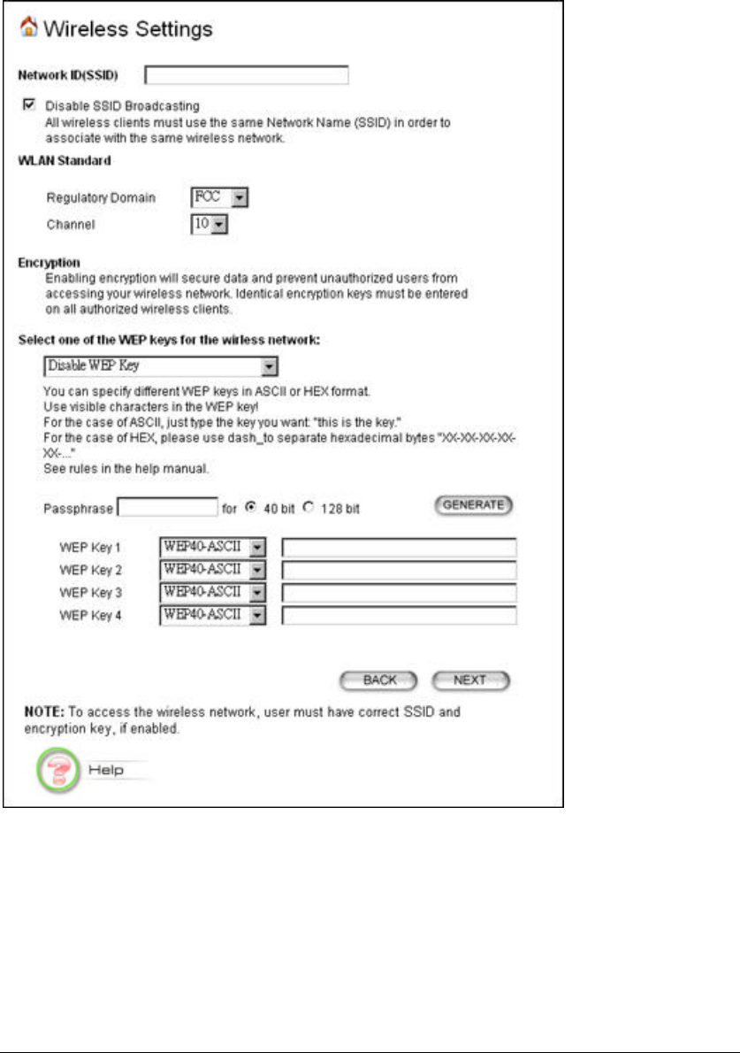
5.2.3 CONFIGURE YOUR WIRELESS LAN CONNECTION
Network Name (SSID): The SSID is the network name used to identify a wireless
network. The SSID must be the same for all devices in the wireless network. Several
Access Points on a network can have the same SSID. The SSID can be up to 30
characters long.
Disable SSID Broadcasting: An Access Point periodically broadcasts its SSID, along
with other information, which allows client stations to learn its existence while
16
searching for Access Points in the wireless network. Select Disable if you do not want
the device to broadcast the SSID.
Channel: Select the channel from the available list to match your network settings.
All devices in the wireless network must use the same channel.
Note: The available channel numbers are different from country to country.
USA and Canada: CH01~11, Europe: CH01~CH13, Japan: CH01~CH14,
France: CH10~CH13, Spain: CH01~CH13.
You can use encryption to protect your data when you are transmitting data
across wireless channels.
WEP Selection: The Access Point allows you to use data encryption to secure your
data from being eavesdropped by unauthorized wireless users. We allow up to four
40-bit encryption keys (WEP40) and four 128-bit encryption keys (WEP128) to be
configured (using either the ASCII or Hexadecimal format) and selected.
WEP Key Setting: The length of a WEP40 key must be equal to 5 and WEP128 key
equal to 13. Once you enable the WEP function, please make sure the same WEP key
is used by both the Access Point and the wireless client stations.
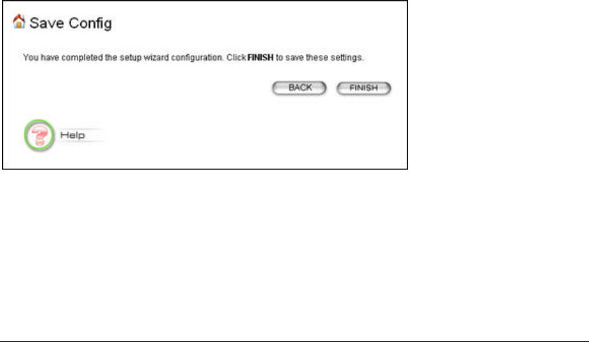
5.2.4 FINISH SETUP WIZARD AND SAVE YOUR SETTINGS
After stepping through the Wizard’s pages, you can press the FINISH button for your
modification to take effect. This will also cause your new settings to be saved into the
permanent memory in your system.
Congratulations! You are now ready to use the Access Point.

17
Note: If you change the AP’s IP address, as soon as you click on FINISH you
will no longer be able to communicate with your Access Point. You need
to change your IP address and then re-boot your computer in order to
resume the communication.