Wistron NeWeb S236 802.11 abgn USB Module User Manual DNUA 85 Manual Eng V1 20110225
Wistron NeWeb Corporation 802.11 abgn USB Module DNUA 85 Manual Eng V1 20110225
User manual.pdf
SHARP Corp.
RUNTKA863WJQZ
802.11 abgn USB Module
User Manual
Version: 1.0
1
Copyright Statement
No part of this publication may be reproduced, stored in a retrieval system, or transmitted in any
form or by any means, whether electronic, mechanical, photocopying, recording or otherwise
without the prior writing of the publisher.
Windows
™
98SE/2000/ME/XP are trademarks of Microsoft
®
Corp.
Pentium is trademark of Intel.
All copyright reserved.
2
Federal Communication Commission Interference Statement
This equipment has been tested and found to comply with the limits for a Class B digital
device, pursuant to Part 15 of the FCC Rules. These limits are designed to provide
reasonable protection against harmful interference in a residential installation. This
equipment generates, uses and can radiate radio frequency energy and, if not installed
and used in accordance with
the instructions, may cause harmful interference to radio communications. However,
there is no guarantee that interference will not occur in a particular installation. If this
equipment does cause harmful interference to radio or television reception, which can be
determined by turning the equipment off and on, the user is encouraged to try to correct
the interference by one of the following measures:
- Reorient or relocate the receiving antenna.
- Increase the separation between the equipment and receiver.
- Connect the equipment into an outlet on a circuit different from that to which the receiver
is connected.
- Consult the dealer or an experienced radio/TV technician for help.
FCC Caution: To assure continued compliance, (example - use only shielded interface
cables when connecting to computer or peripheral devices) any changes or modifications
not expressly approved by the party responsible for compliance could void the user's
authority to operate this equipment.
This device complies with Part 15 of the FCC Rules. Operation is subject to the following
two conditions:
(1) This device may not cause harmful interference, and
(2) This device must accept any interference received, including interference that may
cause undesired operation.
IMPORTANT NOTE:
This transmitter must not be co-located or operating in conjunction with any
other antenna or transmitter.
3
For product available in the USA/Canada market, only channel 1~11 can be operated.
Selection of other channels is not possible.
This device is going to be operated in 5.15~5.25GHz frequency range, it is restricted in
indoor environment only.
IMPORTANT NOTE:
Federal Communication Commission (FCC) Radiation Exposure Statement
This EUT is compliance with SAR for general population/uncontrolled exposure limits in
ANSI/IEEE C95.1-1999 and had been tested in accordance with the measurement
methods and procedures specified in OET Bulletin 65 Supplement C. This equipment
should be installed and operated with minimum distance 0.5 cm between the radiator &
your body.
This equipment complies with FCC radiation exposure limits set forth for an uncontrolled
environment. This equipment should be installed and operated with minimum distance 20cm
between the radiator & your body.

4
Table of Contents
1. INTRODUCTION 5
2. DRIVER/UTILITY INSTALLATION / UNINSTALLATION 6
2.1
I
NSTALLATION
......................................................................................................... 6
2.2
A
DDITIONAL
S
ETUP
P
ROCESSES
............................................................................. 9
2.3
U
NINSTALLATION
.................................................................................................. 10
3. CONNECTING TO AN EXISTING NETWORK 11
4. CREATING AN AD HOC NEW NETWORK 16
5. MODIFYING A WIRELESS NETWORK 20
5.1
I
NFRASTRUCTURE
M
ODE AND
A
D
H
OC
M
ODE
..................................................... 20
5.2
M
ODIFYING A
W
IRELESS
N
ETWORK
.................................................................... 21
5.3
D
EFAULT
S
ETTINGS
W
INDOWS
XP
Z
ERO
-C
ONFIGURATION
............................... 28
5.4
S
UPER
A/G
S
ETTING
.......................................................... 錯誤!
尚未定義書籤。
5
1. Introduction
Thank you for purchasing the 802.11 abgn USB Module that provides the easiest way to wireless
networking. This User Manual contains detailed instructions in the operation of this product.
Please keep this manual for future reference.
System Requirements
A laptop PC contains:
- 32 MB memory or greater
- 300 MHz processor or higher
Microsoft
®
Win
™
2000/ME/98 Second Edition/XP
6
2. Driver/Utility Installation / Uninstallation
2.1 Installation
Note! The Installation Section in this User Manual describes the first-time installation for
Windows. To re-install the driver, please first uninstall the previously installed driver. See
Chapter 2.3 “Uninstallation” in this User Manual.
Follow the steps below to complete the driver/utility installation:
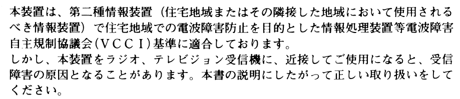
1. Insert the Installation Software CD into the CD-Rom Drive.
2. Click “Next”.
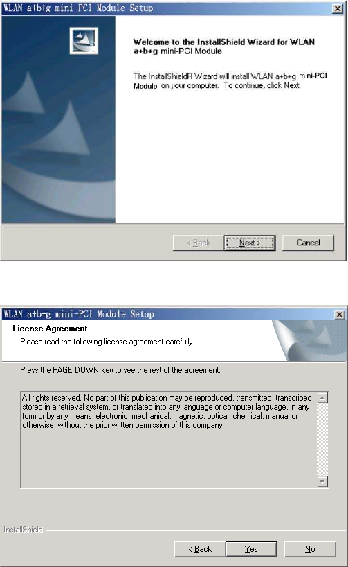
3. Read the License Agreement and click “Yes”.
7
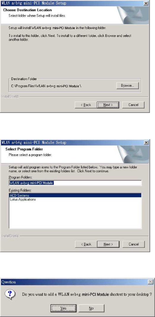
4. Click “Next” to continue or click “Browse” to choose a destination folder.
5. Click “Next”.
6. Click “Yes” to create a shortcut icon on your desktop.
8
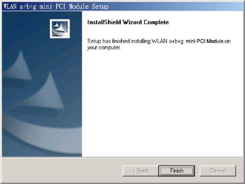
7. Click “Finish”.
8. You should now see a shortcut icon on your desktop.
9
2.2 Additional Setup Processes
During software installation procedure, each operating system may prompt different specific
options:
1. Windows 98SE: The system will request the original Windows CD during the installation
process. When the installation is finished, you’ll have to restart your computer.
2. Windows Me: Please restart your computer when the installation is finished.
3. Windows 2000/XP: Select “Install the software automatically” when the window with this
option appears, and then click “Next” to continue installation.
10
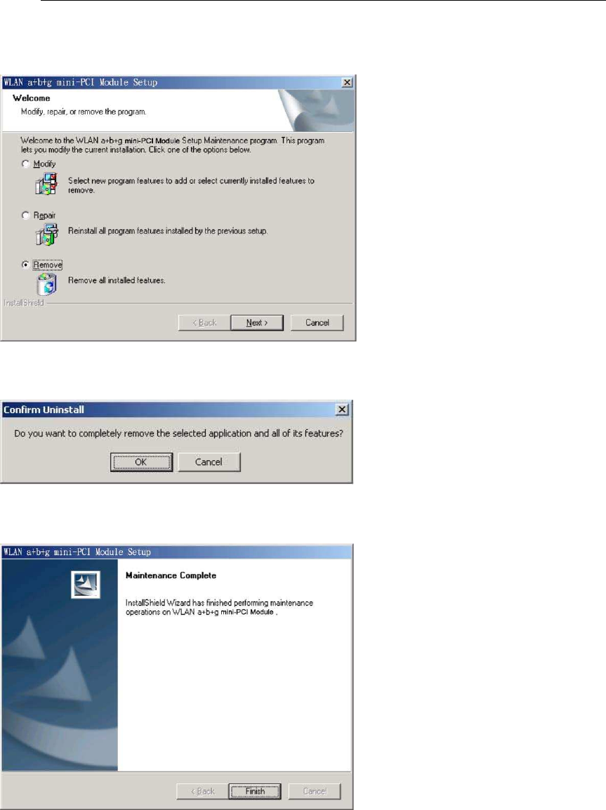
2.3 Uninstallation
Note! Before uninstallation, please close all running programs.
1. Click Start>Programs>802.11 abgn USB Module >UnInstall 802.11 abgn USB Module .
2. Choose “Remove”. Click “Next”.
3. Click “OK” to start Uninstall.
4. Click “Finish”. Uninstall is now completed.
11
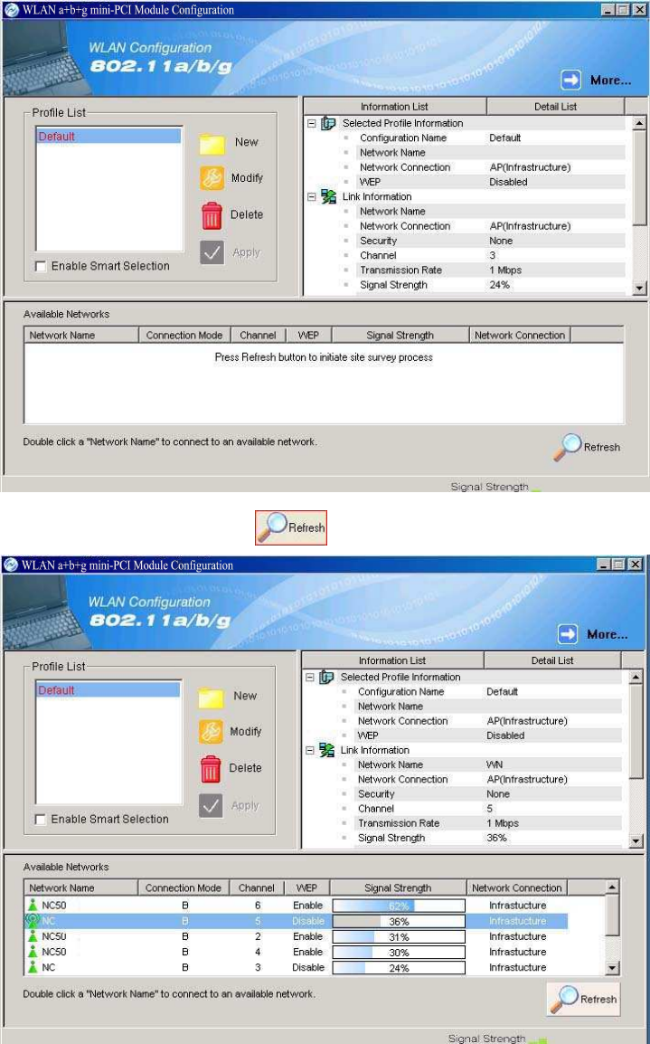
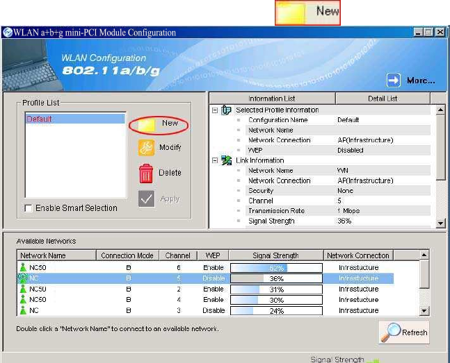
3. Connecting to an Existing Network
1. Double click the shortcut icon of 802.11 abgn USB Module on the desktop, and the
Configuration window appears.
2. Click on the Refresh button to list all available networks.
12
Note! To automatically connect to the network with the strongest signal, select Enable Smart
Selection. Any displays in Profile List.
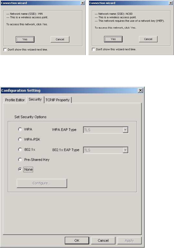
3. From the list of “Available Networks”, choose one network by double clicking the Network
Name. One of the following dialog boxes appears. Click “Yes” to continue.
4. If the chosen network has security enabled, the Security tab displays. Select the security
option used by the network. Contact the network administrator for the correct settings.
5.
If selecting WPA or 802.1X, select the EAP type, then click on the Configure button to select
the certificate.
13
6. If selecting WPA-PSK, click on the Configure button to enter the PassPhrase.
14
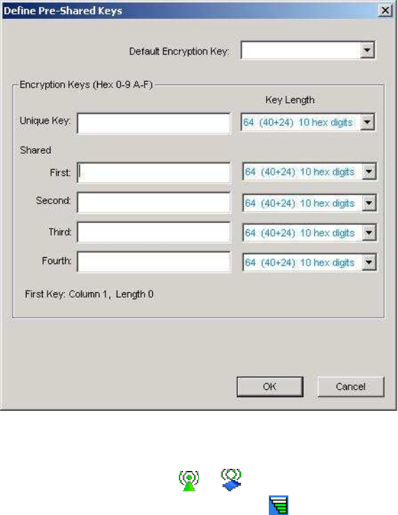
7.
If selecting Pre-Shared Key, click on the Configure button to enter the correct Encryption
Keys.
Key entry method:
a.10hex digits: User must enter 10 hexadecimal digits.
The hexadecimal define is "0-9" and "A-F".
ex: 123456abc
b.5 chars: User must enter 5 characters. ex: ab3#@
c.13 chars: User must enter 13 characters.
ex: ab3#@kf08&kdk
d.16 chars: User must enter 16 characters.
ex: ab3#@kf08&kdk456
For WEP key, please contact with MIS administrator.
8. Click on OK (or Apply if using the other tabs) when done to save the settings.
9. Once connected (the icon or in front of the name of the Connected Network), you can
check the signal strength from the icon in the Windows System Tray.
15
Additional Note for Windows XP
In Windows XP, it is recommended that you use the 802.11 abgn USB Module Configuration
Utility. Before using the Utility, please follow the steps below to disable the Windows XP Zero
Configuration:
Option 1:
1. Double click the shortcut icon to open the Utility.
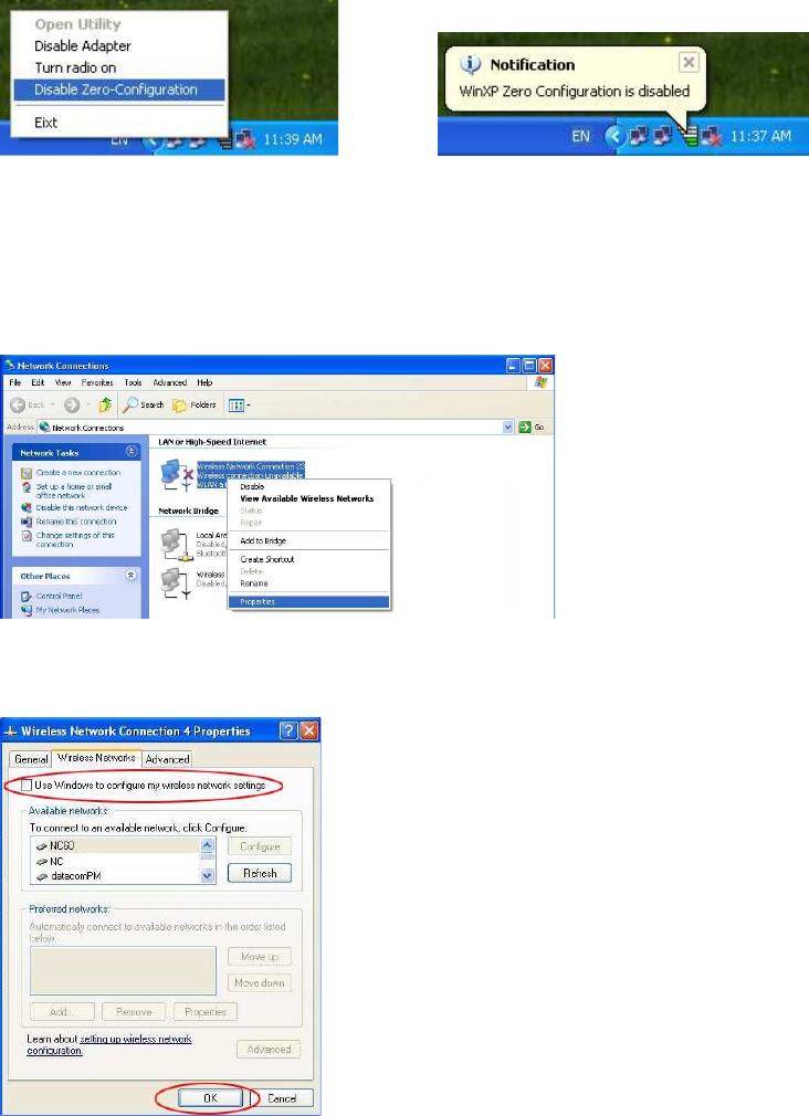
2. From the Windows System Tray, you should see the signal icon. Right-click it and select
“Disable Zero-Configuration”.
Option 2:
1. Go to “Control Panel” and double click “Network Connections”.
2. Right-click “Wireless Network Connection” of “802.11 abgn USB Module ”, and select
“Properties”.
3. Select “Wireless Networks” tab, and uncheck the check box of “Use Windows to configure
my wireless network settings”, and then click “OK”.
16
4. Creating an Ad Hoc New Network
NOTE! Ad-hoc mode is available only for 802.11b/g. It is not available for 802.11a. This is a
client product and do not have radar detection function specified by FCC. The software will not
let you to use ad-hoc under 802.11a.
1. In the Configuration window, click New .
2.
Select the “Profile Editor” tab.
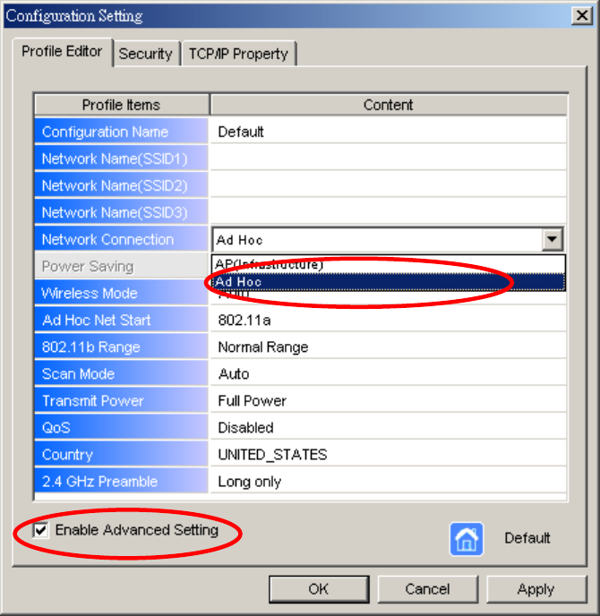
17
3. Choose the check box of Enable Advanced Setting to edit all settings.
4. If joining or creating an Ad-Hoc network, choose Ad Hoc.
5. Click OK (or Apply if using the other tabs) to save the settings.
For details of each setting, refer to Modifying a Wireless Network on page 20.
6. Click the Security tab. If not using security, select None.
18
7.
If security is used, select Pre-Shared Key and click on the Configure button.
19
8. Enter an encryption key in the Shared: First field.
9. Click OK (or Apply if using the other tabs) to save the settings. The new Network Name is
listed in the Profile List.
The driver does not allow channel selection in Ad-Hoc mode. Instead, the driver starts with an
initial channel then checks channel status. If the channel is busy, the driver automatically uses
a different channel.
For details of each setting, please see chapter 5.
20
5. Modifying a Wireless Network
5.1 Infrastructure Mode and Ad Hoc Mode
You can set the Wireless Network Adapter to work in either Infrastructure mode or Ad Hoc
mode.
NOTE! Ad-hoc mode is available only for 802.11b/g. It is not available for 802.11a. This is a
client product and do not have radar detection function specified by FCC. The software will not
let you to use ad-hoc under 802.11a.
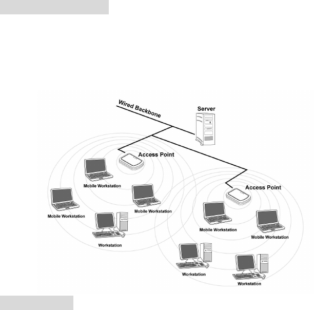
Infrastructure Mode
In infrastructure mode, devices communicate with each other by first going through an Access
Point (AP). Wireless devices can communicate with each other or can communicate with a
wired network. When one AP is connected to wired network and a set of wireless stations, it is
referred to as a BSS (Basic Service Set).
Ad Hoc Mode
Ad-hoc mode is also called “peer-to-peer mode” or “Independent Basic Service Set (IBSS)”. In
ad hoc mode, devices communicate directly with each other without using an Access Point (AP).
NOTE! Ad-hoc mode is available only for 802.11b/g. It is not available for 802.11a. This is a
client product and do not have radar detection function specified by FCC. The software will not
let you to use ad-hoc under 802.11a.
21
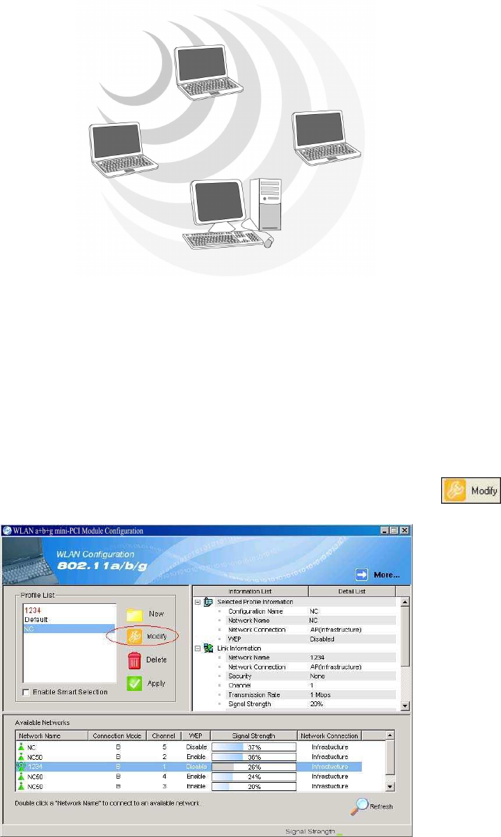
5.2 Modifying a Wireless Network
1. Open “802.11 abgn USB Module Configuration” by double clicking the shortcut icon on the
desktop.
Note! If there’s no network name listed in the “Profile List”, click Refresh button and
double click a Network Name from Available Networks. The chosen Network
Name is listed in the Profile List.
2. From the Profile List, select one Profile and click Modify button .
22
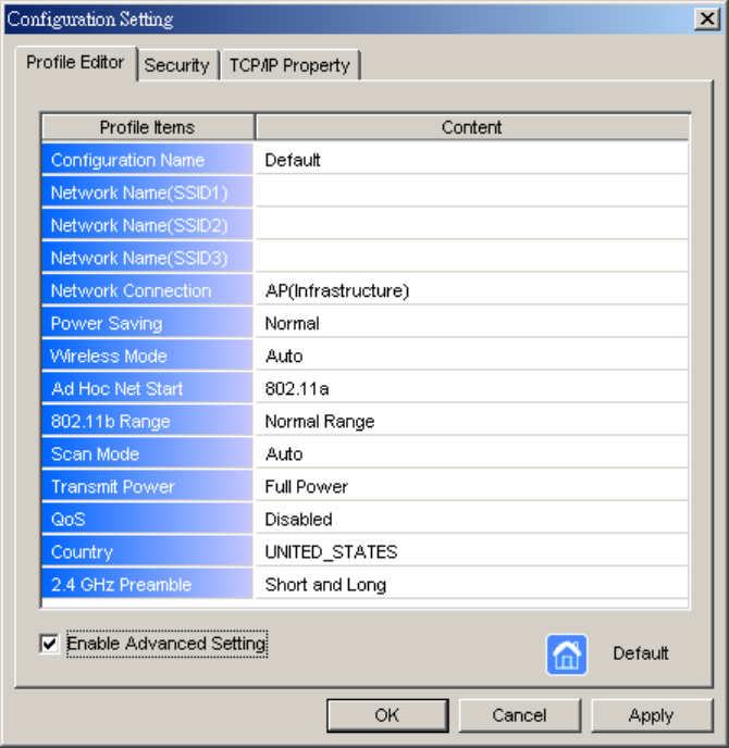
3. Select Profile Editor tab and edit the settings. Click OK to save the modifications.
Configuration Name: This name identifies the configuration. This name should be
unique.
Network Name (SSID1) (SSID2) (SSID3): The name of the wireless network. This
name cannot be longer than 32 characters. If the field is set to be “ANY” or is left
blank, your computer will connect to an AP with the best signal strength.
Network Connection: Specifies the mode of the network. Two options are
“Infrastructure” and “Ad Hoc”.
Power Saving: Minimizes power consumption while maintaining network connectivity
and high data transfer performance. In Ad Hoc mode, Power Savings function cannot
be enabled. The power management options are:
• Off: PC Card is powered up at all times.
• Normal: PC Card sleeps less often and stays asleep for a shorter period.
• Maximum: PC Card sleeps more frequently and stays asleep as much as
possible.
Wireless Mode: Three options are “802.11b”, “802.11a”, “802.11g”, “Super A”, “Super
G” or “Auto”. “Auto” allows the use of either 802.11a, 802.11g or 802.11b mode.
NOTE! Ad-hoc mode is available only for 802.11b/g. It is not available for 802.11a.
23
This is a client product and do not have rador detection function specified by FCC.
The software will not let you to use ad-hoc under 802.11a.
Ad Hoc Net Start: Specifies a band to establish an Ad Hoc network if no matching
SSID is found. Options available are the following: 802.11b and 802.11g.
NOTE! Ad-hoc mode is available only for 802.11b/g. It is not available for 802.11a.
This is a client product and do not have radar detection function specified by FCC.
The software will not let you to use ad-hoc under 802.11a.
802.11b Range: Options are Normal Range and Extended Range. This function can
let user to determine the transfer range in 802.11b mode. Extended Range can prolong
the transfer range with a lower data transmitting rate.
Scan Mode: Options are Active Scan, Passive Scan and Auto. In Active Scan, the
driver sends out the probe request frames from each channel and collects the response
frames from the responding. In Passive Scan, the driver scan each requested channel,
listening the beacons on each channel.
Transmit Power: This setting allows you to change the output power of the PC Card to
increase or decrease the coverage area.
QoS: Disables or enables the PC Card to cooperate in a network using QoS
(Quality of Service).
2.4 GHz Preamble: Allows Ad-Hoc compatibility with other 2.4 GHz devices. Two
options are Short and Long and Long only. Use Long Only when configuring the
client for an 802.11b RoamAbout AP wireless network.
24
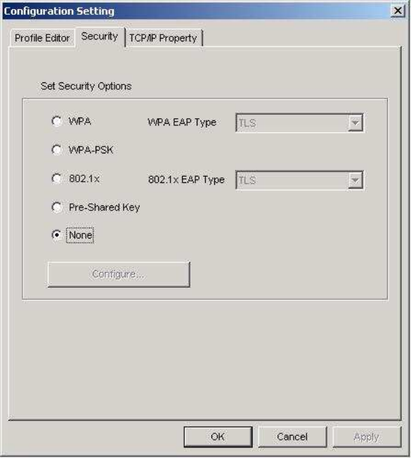
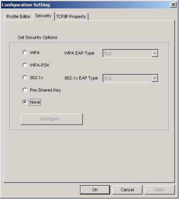
4. Select Security tab and choose the security mode.
Note! Check with your Network Administrator for the security features supported by your AP.
WPA: Enables the use of WiFi protected Access (WPA). This option requires IT
administration.
a) Select WPA to open the WPA EAP drop-down menu. The options includes TLS and
PEAP.
b) Click on the Configure button and complete the configuration information in the
Define Certificate dialog.
WPA-PSK: Enables the WPA-Pre Shared Key (PSK). Click on the Configure button
and complete the configuration information in the WPA Passphrase dialog.
802.1x: Enables 802.1x security. This option requires IT administration.
a) Select 802.1x to open the 802.1x EAP drop-down menu. The options include TLS
and PEAP.
b) Click on the Configure button and complete the configuration information in the
Define Certificate dialog.
25
Pre-Shared Key: Enables the use of pre-shared keys that are defined on the AP and the
station.
a) Select the Pre-Shared Key radio button.
b) Click on the Configure button and complete the configuration information in the
Define Certificate dialog.
None: No security.
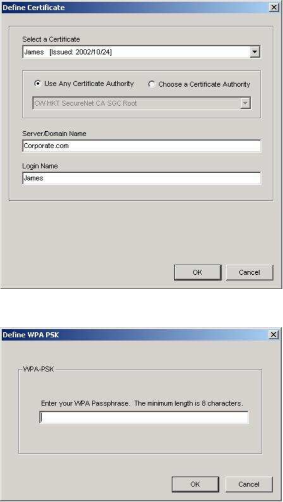
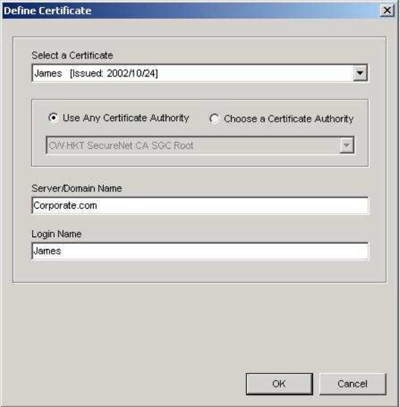
5. Define the Certificate.
Select a Certificate: Select the Certificate to Authenticate to the RADIUS server from
the drop-down menu.
Use any Certificate Authority: The Default Setting. Select this radio button to use any
Certificate Authority (CA) for authentication.
Choose a Certificate Authority: Select this radio button to choose the desired
Certificate Authority for authentication from the drop-down menu.
Server/Domain Name: The the RADIUS server name or the domain name used for the
network access.
Login Name: The username used to log into the server or domain.
Define User Information (PEAP): Click on the Define User Information button and
complete the configuration information in the Define User Information dialog.
6. If selecting WPA-PSK, click on the Configure button to enter the PassPhrase. The
26
PassPhrase must be a minimum of 8 printable ASCII characters. The PassPhrase
should be at
least 20 characters to make it more difficult for an attacker to decipher the key.
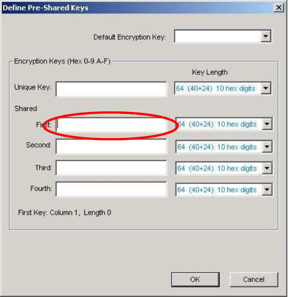
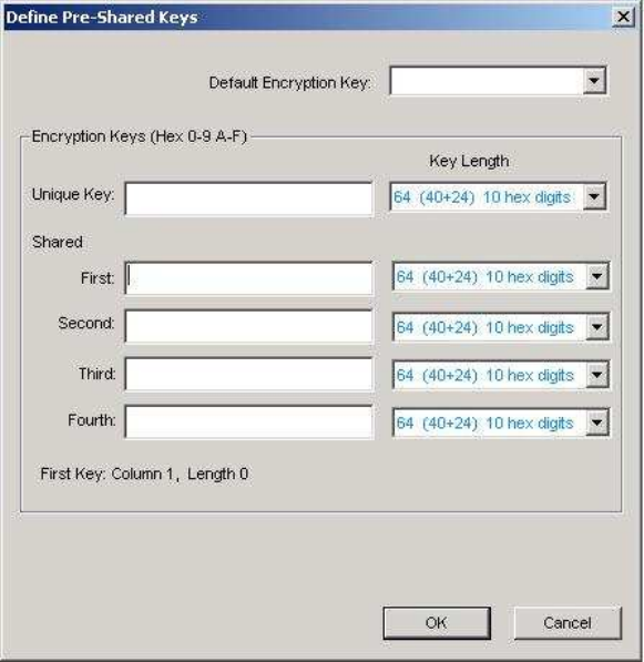
7. If selecting Pre-Shared Key, click on the Configure button to enter the Encryption
Keys.When finished, click OK. For WEP key, please contact with MIS administrator.
Key Entry Method: Determines the entry method for the key. Hexadecimal (0-9, A-F) or
ASCII text (all keyboard characters).
Default Encryption Key: Allows you to choose one encryption key (First, Second, Third,
or Fourth) as the transmit key, which encrypts transmissions from the PC Card.
Unique Key: Defines the per-session encryption key for the current network
configuration. Not used in Ad-Hoc mode.
Shared Keys: Use these fields to enter the wireless network’s encryption keys. The keys
must be in the correct position (First, Second, Third, or Fourth).
Key Length: Defines the length of each encryption key.
o For 40/64 bit (enter 10 digits for hexadecimal or 5 characters for ASCII)
o For 104/128 bit (Enter 26 digits for hexadecimal or 13 characters for ASCII)
When the length is changed, the number of available characters in the field automatically
changes. If a previously entered key is too long, the key is automatically truncated to fit. If
the key length is increased again, the key does not update to the previous value.
27
8. Click OK to save the settings.
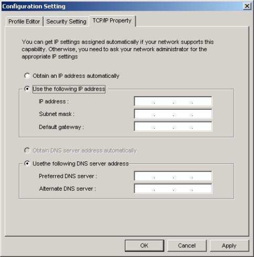
9. Select “TCP/IP Property” tab. Enter the settings and click “OK” to save the settings.
If the network uses DHCP server, choose Obtain an IP address automatically.
If the network does not use DHCP server, choose Use the following IP address to set the
relative settings. For the IP configuration information, please contact the network
administrator.
28
5.3 Default Settings Windows XP Zero-Configuration
You may also choose the default parameters and directly proceed to Windows XP
zero-configuration through the steps below:
1. Go to “Control Panel” and open “Network Connections”.
2. Right-click the Wireless Network Connection of “802.11 abgn USB Module ”, and make sure
this connection is Enabled.
3. Right-click the Wireless Network Connection of “802.11 abgn USB Module ”, and then click
“Properties”.
4. Select “Wireless Networks” tab and select “Use Windows to configure my wireless network
settings” check box.
Note! Clear the check box of “Use Windows to configure my wireless network settings” will
disable automatic wireless network configuration.
29
Appendix A: FAQ about WLAN
1. Can I run an application from a remote computer over the wireless network?
This will depend on whether or not the application is designed to be used over a network. Consult
the application’s user guide to determine whether it supports operation over a network.
2. Can I play computer games with other members of the wireless network?
Yes, as long as the game supports multiple players over a LAN (local area network).
Refer to the game’s user guide for more information.
3. What is Spread Spectrum?
Spread Spectrum technology is a wideband radio frequency technique developed by the military
for use in reliable, secure, mission-critical communications systems. It is designed to trade off
bandwidth efficiency for reliability, integrity, and security. In other words, more bandwidth is
consumed than in the case of narrowband transmission, but the trade-off produces a signal that is,
in effect, louder and thus easier to detect, provided that the receiver knows the parameters of the
spread-spectrum signal being broadcast. If a receiver is not tuned to the right frequency, a
spread-spectrum signal looks like background noise. There are two main alternatives, Direct
Sequence Spread Spectrum (DSSS) and Frequency Hopping Spread Spectrum (FHSS).
4. What is DSSS? What is FHSS? And what are their differences?
Frequency-Hopping Spread-Spectrum (FHSS) uses a narrowband carrier that changes frequency
in a pattern that is known to both transmitter and receiver. Properly synchronized, the net effect is
to maintain a single logical channel. To an unintended receiver, FHSS appears to be
short-duration impulse noise. Direct-Sequence Spread-Spectrum (DSSS) generates a redundant
bit pattern for each bit to be transmitted. This bit pattern is called a chip (or chipping code). The
longer the chip, the greater the probability that the original data can be recovered. Even if one or
more bits in the chip are damaged during transmission, statistical techniques embedded in the
radio can recover the original data without the need for retransmission. To an unintended receiver,
DSSS appears as low power wideband noise and is rejected (ignored) by most narrowband
receivers.
30
5. Would the information be intercepted while transmitting on air?
WLAN features two-fold protection in security. On the hardware side, as with Direct Sequence
Spread Spectrum technology, it has the inherent security feature of scrambling. On the software
side, WLAN offers the encryption function (WEP) to enhance security and access control.
6. What is WEP?
WEP is Wired Equivalent Privacy, a data privacy mechanism based on a 64-bit or 128-bit shared
key algorithm, as described in the IEEE 802.11 standard.
7. What is infrastructure mode?
When a wireless network is set to infrastructure mode, the wireless network is configured to
communicate with a wired network through a wireless access point.
8. What is roaming?
Roaming is the ability of a portable computer user to communicate continuously while moving
freely throughout an area greater than that covered by a single access point. Before using the
roaming function, the workstation must make sure that it is the same channel number with the
access point of dedicated coverage area.
To achieve true seamless connectivity, the wireless LAN must incorporate a number of different
functions. Each node and access point, for example, must always acknowledge receipt of each
message. Each node must maintain contact with the wireless network even when not actually
transmitting data. Achieving these functions simultaneously requires a dynamic RF networking
technology that links access points and nodes. In such a system, the user’s end node undertakes a
search for the best possible access to the system. First, it evaluates such factors as signal strength
and quality, as well as the message load currently being carried by each access point and the
distance of each access point to the wired backbone. Based on that information, the node next
selects the right access point and registers its address. Communications between end node and
host computer can then be transmitted up and down the backbone. As the user moves on, the end
node’s RF transmitter regularly checks the system to determine whether it is in touch with the
original access point or whether it should seek a new one. When a node no longer receives
acknowledgment from its original access point, it undertakes a new search. Upon finding a new
access point, it then re-registers, and the communication process continues.

FCCstatement
ExposureStatement:
ThisequipmentcomplieswithFCCradiationexposurelimitssetforthforan
uncontrolledenvironment.Thisequipmentshouldbeinstalledandoperated
withminimumdistance20cmbetweentheradiator&yourbody.
ThisdeviceisintendedonlyforOEMintegratorsunderthefollowingconditions:
1) Theantennamustbeinstalledsuchthat20cmismaintainedbetweenthe
antennaandusers,and
2) Thetransmittermodulemaynotbeco‐locatedwithanyothertransmitter
orantenna.
Aslongas2conditionsabovearemet,furthertransmittertestwillnotbe
required.However,theOEMintegratorisstillresponsiblefortestingtheir
end‐productforanyadditionalcompliancerequirementsrequiredwiththis
moduleinstalled
IMPORTANTNOTE:Intheeventthattheseconditionscannotbemet(for
examplecertainlaptopconfigurationsorco‐locationwithanother
transmitter),thentheFCCauthorizationisnolongerconsideredvalidandthe
FCCIDcannotbeusedonthefinalproduct.Inthesecircumstances,theOEM
integratorwillberesponsibleforre‐evaluatingtheendproduct(includingthe
transmitter)andobtainingaseparateFCCauthorization.
EndProductLabeling
Thistransmittermoduleisauthorizedonlyforuseindevicewheretheantenna
maybeinstalledsuchthat20cmmaybemaintainedbetweentheantennaand
users.Thefinalendproductmustbelabeledinavisibleareawiththefollowing:
“ContainsFCCID:NKR‐S236”.Thegrantee'sFCCIDcanbeusedonlywhenall
FCCcompliancerequirementsaremet.
ManualInformationTotheEndUser
The OEM integrator has to be aware not to provide information to the end user
regarding how to install or remove this RF module in the user’s manual of the
end product which integrates this module.
Theendusermanualshallincludeallrequiredregulatoryinformation/warning
asshowinthismanual.
ICstatement
ThisdevicecomplieswithRSS‐210oftheIndustryCanadaRules.Operationissubject
tothefollowingtwoconditions:(1)Thisdevicemaynotcauseharmfulinterference,
and(2)thisdevicemustacceptanyinterferencereceived,includinginterferencethat
maycauseundesiredoperation.
CedispositifestconformeàlanormeCNR‐210d'IndustrieCanadaapplicableaux
appareilsradioexemptsdelicence.Sonfonctionnementestsujetauxdeux
conditionssuivantes:(1)ledispositifnedoitpasproduiredebrouillagepréjudiciable,
et(2)cedispositifdoitacceptertoutbrouillagereçu,ycomprisunbrouillage
susceptibledeprovoquerunfonctionnementindésirable.
Caution:
(i)thedeviceforoperationintheband5150‐5250MHzisonlyforindooruseto
reducethepotentialforharmfulinterferencetoco‐channelmobilesatellitesystems;
(ii)themaximumantennagainpermittedfordevicesinthebands5250‐5350MHz
and5470‐5725MHzshallcomplywiththee.i.r.p.limit;and
(iii)themaximumantennagainpermittedfordevicesintheband5725‐5825MHz
shallcomplywiththee.i.r.p.limitsspecifiedforpoint‐to‐pointandnonpoint‐to‐point
operationasappropriate.
(iv)Usersshouldalsobeadvisedthathigh‐powerradarsareallocatedasprimary
users(i.e.priorityusers)ofthebands5250‐5350MHzand5650‐5850MHzandthat
theseradarscouldcauseinterferenceand/ordamagetoLE‐LANdevices.
Avertissement:
Leguided’utilisationdesdispositifspourréseauxlocauxdoitincluredesinstructions
précisessurlesrestrictionssusmentionnées,notamment:
(i)lesdispositifsfonctionnantdanslabande5150‐5250MHzsontréservés
uniquementpouruneutilisationàl’intérieurafinderéduirelesrisquesdebrouillage
préjudiciableauxsystèmesdesatellitesmobilesutilisantlesmêmescanaux;
(ii)legainmaximald’antennepermispourlesdispositifsutilisantlesbandes5250‐5
350MHzet5470‐5725MHzdoitseconformeràlalimitedep.i.r.e.;
(iii)legainmaximald’antennepermis(pourlesdispositifsutilisantlabande5725‐5
825MHz)doitseconformeràlalimitedep.i.r.e.spécifiéepourl’exploitationpointà
pointetnonpointàpoint,selonlecas.
(iv)Deplus,lesutilisateursdevraientaussiêtreavisésquelesutilisateursderadars
dehautepuissancesontdésignésutilisateursprincipaux(c.‐à‐d.,qu’ilsontlapriorité)
pourlesbandes5250‐5350MHzet5650‐5850MHzetquecesradarspourraient
causerdubrouillageet/oudesdommagesauxdispositifsLAN‐EL.
RadiationExposureStatement:
ThisequipmentcomplieswithICradiationexposurelimitssetforthforan
uncontrolledenvironment.Thisequipmentshouldbeinstalledandoperatedwith
minimumdistance20cmbetweentheradiator&yourbody.
Déclarationd'expositionauxradiations:
Cetéquipementestconformeauxlimitesd'expositionauxrayonnementsICétablies
pourunenvironnementnoncontrôlé.Cetéquipementdoitêtreinstalléetutilisé
avecunminimumde20cmdedistanceentrelasourcederayonnementetvotre
corps.
This device is intended only for OEM integrators under the following conditions: (For
module device use)
1)Theantennamustbeinstalledsuchthat20cmismaintainedbetweentheantenna
andusers,and
2)Thetransmittermodulemaynotbeco‐locatedwithanyothertransmitteror
antenna.
Aslongas2conditionsabovearemet,furthertransmittertestwillnotberequired.
However,theOEMintegratorisstillresponsiblefortestingtheirend‐productforany
additionalcompliancerequirementsrequiredwiththismoduleinstalled.
Cet appareil est conçu uniquement pour les intégrateurs OEM dans les conditions
suivantes: (Pour utilisation de dispositif module)
1) L'antennedoitêtreinstalléedetellesortequ'unedistancede20cmest
respectéeentrel'antenneetlesutilisateurs,et
2) Lemoduleémetteurpeutnepasêtrecoïmplantéavecunautreémetteurou
antenne.
Tantqueles2conditionsci‐dessussontremplies,desessaissupplémentairessur
l'émetteurneserontpasnécessaires.Toutefois,l'intégrateurOEMesttoujours
responsabledesessaissursonproduitfinalpourtoutesexigencesdeconformité
supplémentairesrequispourcemoduleinstallé.
IMPORTANTNOTE:
Intheeventthattheseconditionscannotbemet(forexamplecertainlaptop
configurationsorco‐locationwithanothertransmitter),thentheCanada
authorizationisnolongerconsideredvalidandtheICIDcannotbeusedonthefinal
product.Inthesecircumstances,theOEMintegratorwillberesponsiblefor
re‐evaluatingtheendproduct(includingthetransmitter)andobtainingaseparate
Canadaauthorization.
NOTEIMPORTANTE:
Danslecasoùcesconditionsnepeuventêtresatisfaites(parexemplepourcertaines
configurationsd'ordinateurportableoudecertainesco‐localisationavecunautre
émetteur),l'autorisationduCanadan'estplusconsidérécommevalideetl'IDICne
peutpasêtreutilisésurleproduitfinal.Danscescirconstances,l'intégrateurOEM
serachargéderéévaluerleproduitfinal(ycomprisl'émetteur)etl'obtentiond'une
autorisationdistincteauCanada.
EndProductLabeling
Thistransmittermoduleisauthorizedonlyforuseindevicewheretheantennamay
beinstalledsuchthat20cmmaybemaintainedbetweentheantennaandusers.The
finalendproductmustbelabeledinavisibleareawiththefollowing:“ContainsIC:
4441A‐S236”.
Plaquesignalétiqueduproduitfinal
Cemoduleémetteurestautoriséuniquementpouruneutilisationdansundispositif
oùl'antennepeutêtreinstalléedetellesortequ'unedistancede20cmpeutêtre
maintenueentrel'antenneetlesutilisateurs.Leproduitfinaldoitêtreétiquetédans
unendroitvisibleavecl'inscriptionsuivante:"ContientdesIC:4441A‐S236".
ManualInformationTotheEndUser
TheOEMintegratorhastobeawarenottoprovideinformationtotheenduser
regardinghowtoinstallorremovethisRFmoduleintheuser’smanualoftheend
productwhichintegratesthismodule.
Theendusermanualshallincludeallrequiredregulatoryinformation/warningas
showinthismanual.
Manueld'informationàl'utilisateurfinal
L'intégrateurOEMdoitêtreconscientdenepasfournirdesinformationsà
l'utilisateurfinalquantàlafaçond'installeroudesupprimercemoduleRFdansle
manueldel'utilisateurduproduitfinalquiintègrecemodule.
Lemanueldel'utilisateurfinaldoitincluretouteslesinformationsréglementaires
requisesetavertissementscommeindiquédanscemanuel.