Wistron NeWeb UPAST5 Satellite Radio PnP Receiver User Manual ST5 Installation User Guide 022108a indd
Wistron NeWeb Corporation Satellite Radio PnP Receiver ST5 Installation User Guide 022108a indd
UserManual.wiki
>
Wistron NeWeb
>
UPAST5 User Manual
users manual
Navigation menu
Upload a User Manual
Namespaces
Wiki Guide
HTML
PDF
Info
Views
User Manual
Discussion / Help
Navigation
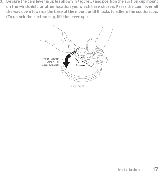
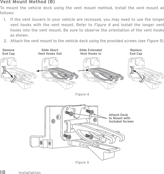
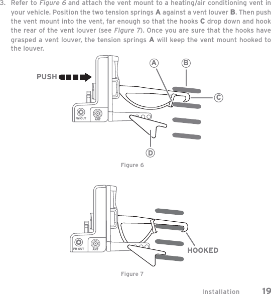
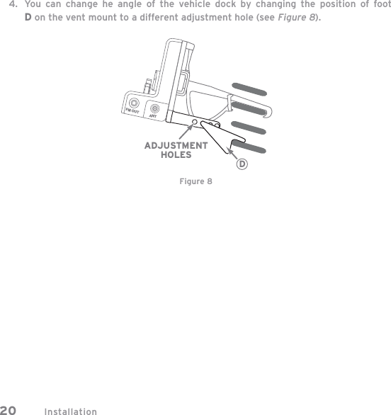
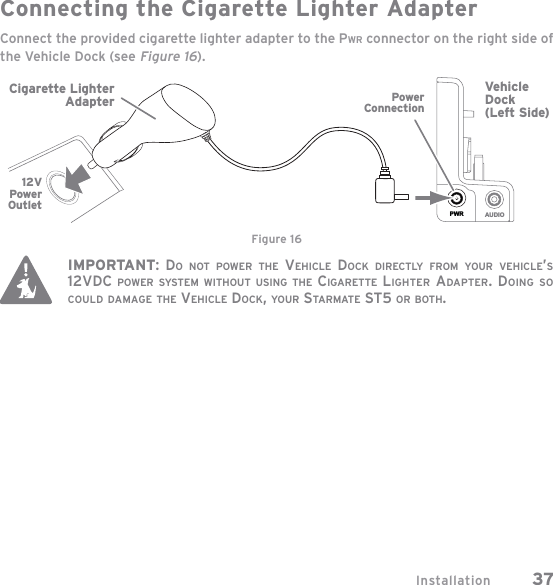
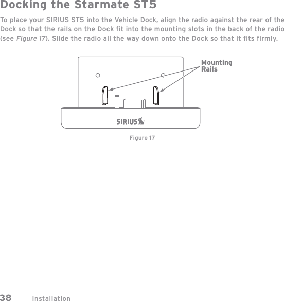
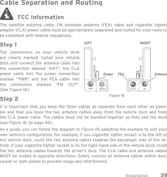
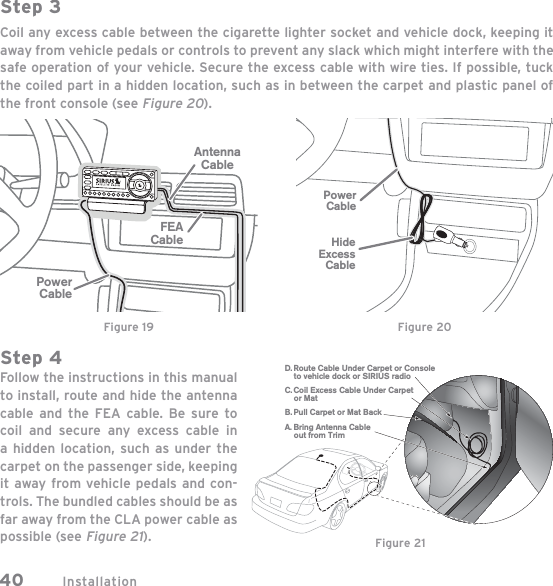
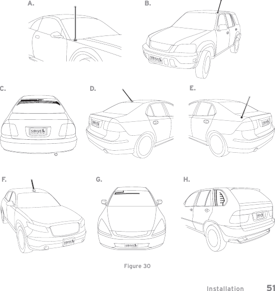
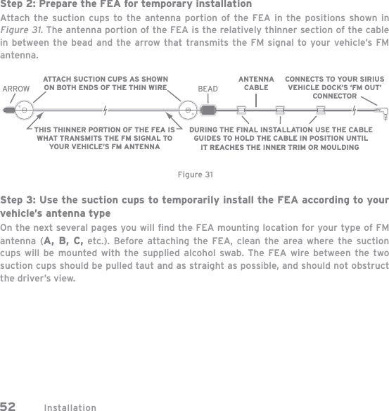
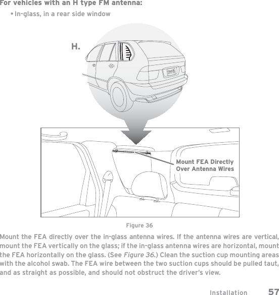
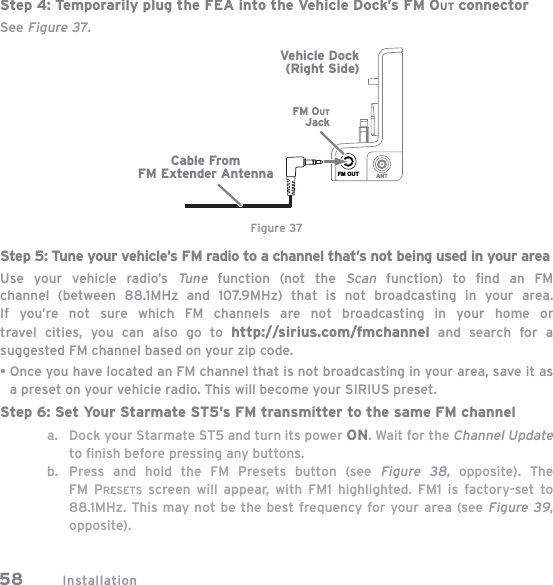
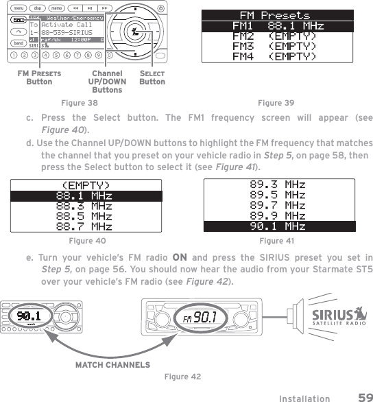
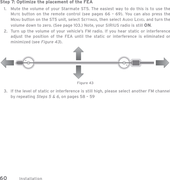
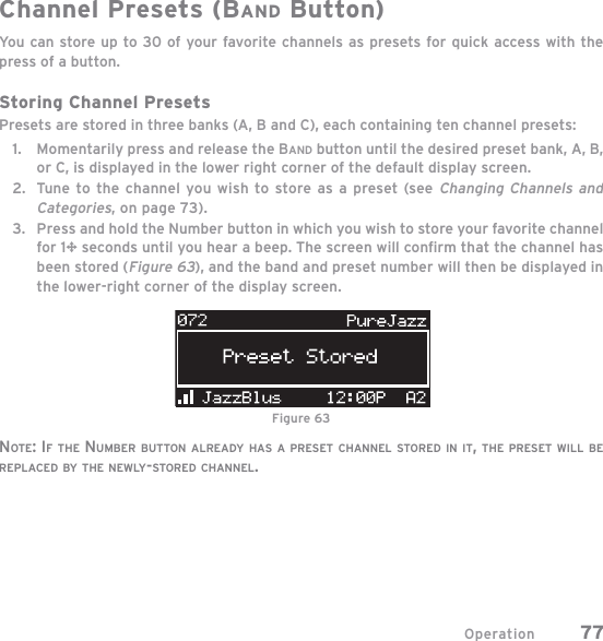
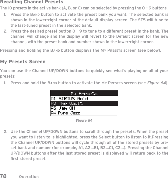
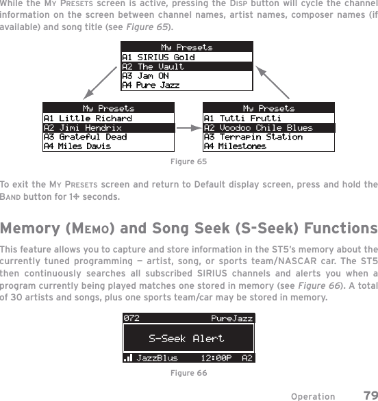
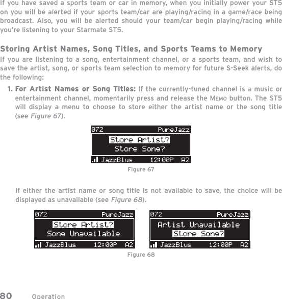
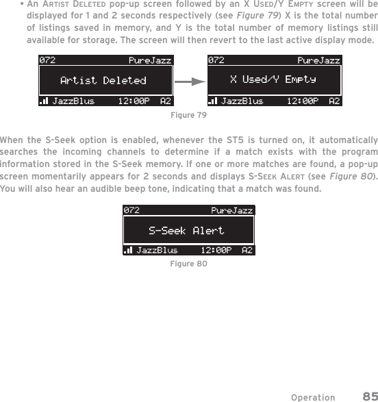
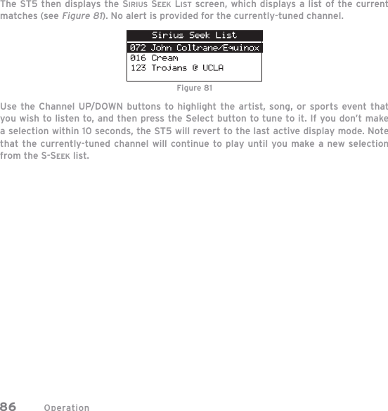
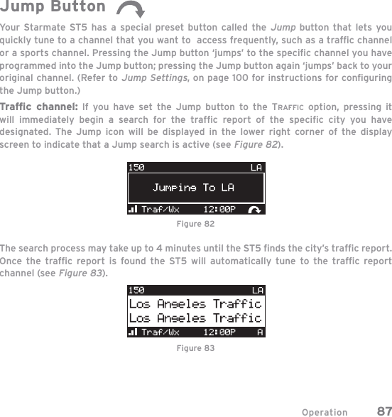
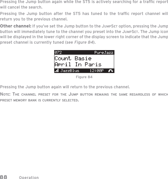
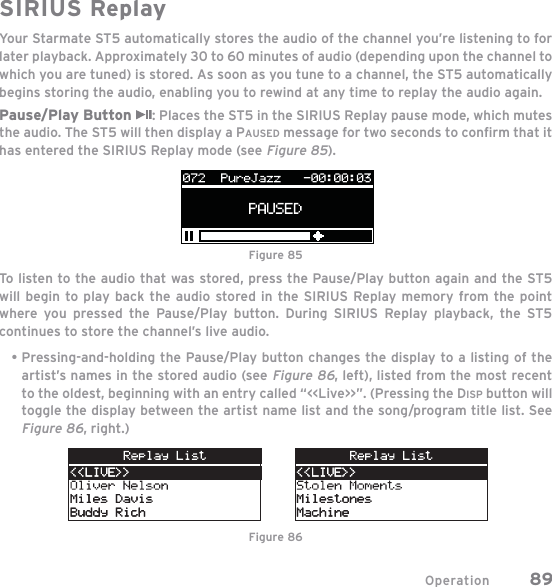
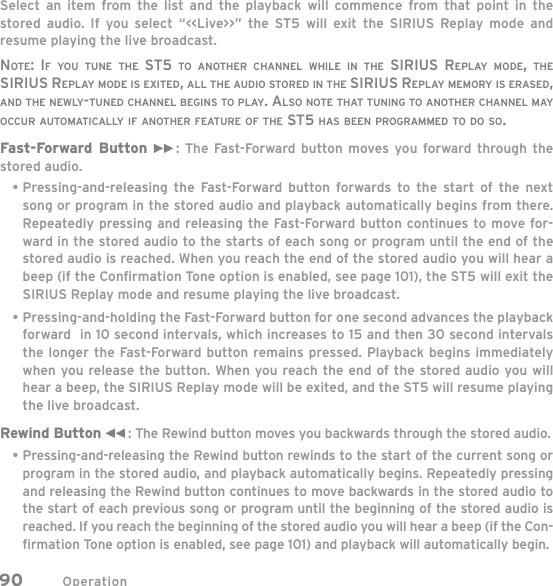
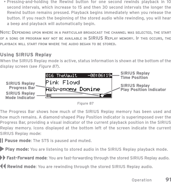
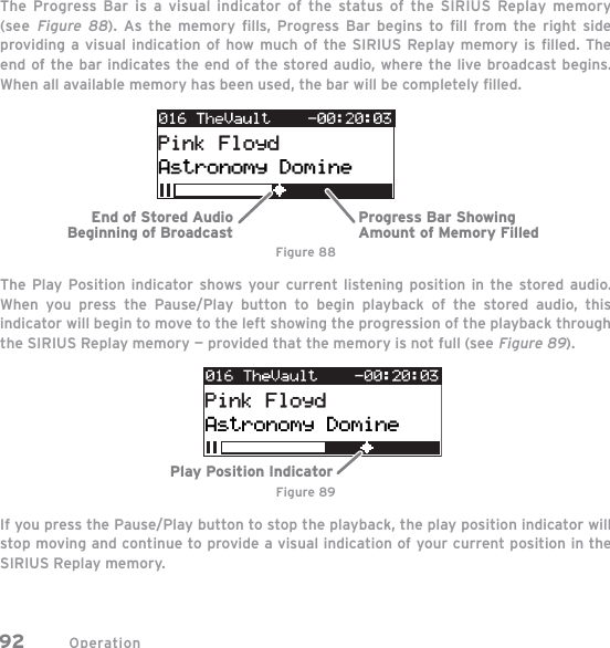
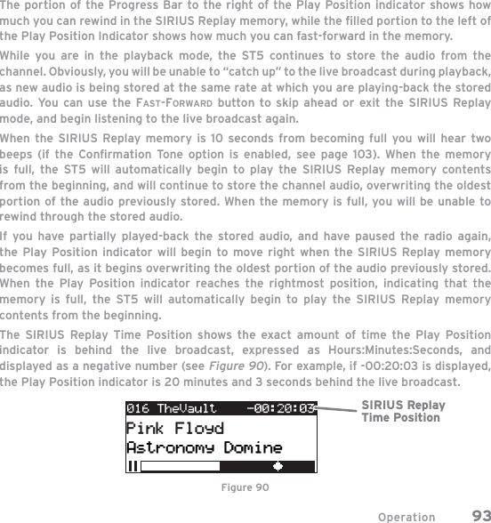
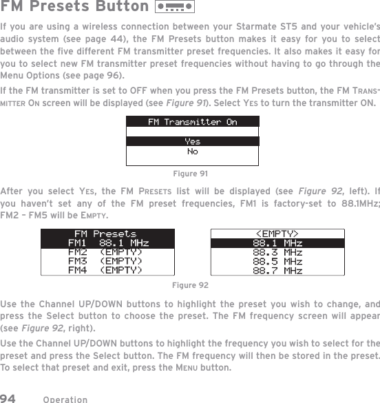
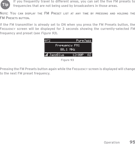
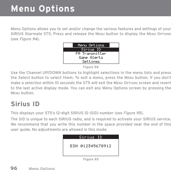
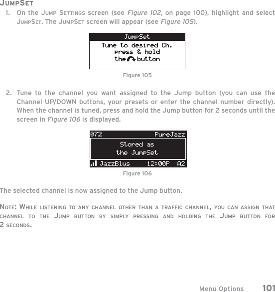
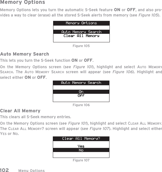
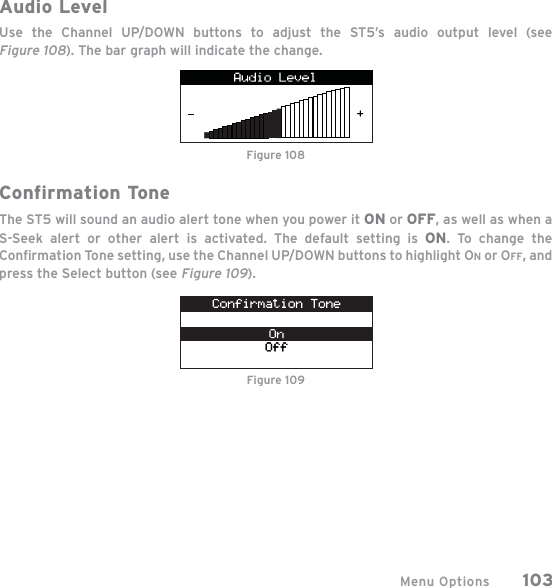
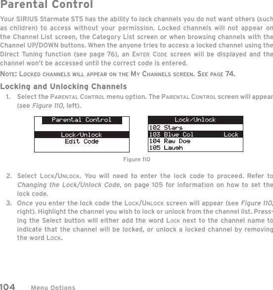
![IC StatementThis Class B or A digital apparatus complies with Canadian ICES-003.Operation is subject to the following two conditions: (1) this device may not cause interference, and (2) this device mustaccept any interference, including interference that may cause undesired operation of the device.Cet appareil numérique de la classe B or A conforme á la norme NMB-003 du Canada.Operation is subject to the following two conditions: (1) this device may not cause interference and (2) this device mustaccept any interference, including interference that may cause undesired operation of the device.Country Code StatementFor product available in the USA/Canada market, only channel 1~11 can be operated. Selection of other channels is notpossible.This device and its antenna(s) must not be co-located or operation in conjunction with any other antenna or transmitter.To reduce potential radio interference to other users, the antenna type and its gain should be so chosen that theequivalent isotropically radiated power (e.i.r.p) is not more than that permitted for successful communication.RSS-GEN issue 2(7.1.4) Transmitter AntennaThis device has been designed to operate with the antennas listed below, and having a maximum gain of [x] dB.Antennas not included in this list or having a gain greater than [x] dB are strictly prohibited for use with this device. Therequired antenna impedance is 50 ohms.RSS-GEN issue 2 (7.1.3) External AmplifiersIn accordance with Industry Canada Regulations, this radio frequency power amplifier may only be used with atransmitter with which the amplifier has been certified by Industry Canada. This Industry Canada Identification Numberfor the transmitter with which this amplifier is permitted to operate is…(XXX~XXX MHz)RSS-210 Issue 7 Annex 9 A9.5(4)The device could automatically discontinue transmission in case of absence of information to transmit, or operationalfailure. Note that this is not intended to prohibit transmission of control or signaling information or the use of repetitivecodes where required by the technology.](https://usermanual.wiki/Wistron-NeWeb/UPAST5/User-Guide-923310-Page-119.png)