Wistron NeWeb UPASV301 Satellite Radio PnP Receiver User Manual
Wistron NeWeb Corporation Satellite Radio PnP Receiver Users Manual
Users Manual

Satellite Radio Plug-n-Play Receiver
SIRIUS STRATUS
SV3 User Guide

Congratulations on the Purchase of your new SIRIUS Stratus SV3
Plug-n-Play Receiver
Your new SIRIUS Stratus SV3 Plug-n-Play Receiver lets you enjoy SIRIUS® Satellite Radio’s
digital entertainment in any vehicle where you’ve installed the included vehicle docking station.
The Stratus SV3 is also compatible with the SUPH1 SIRIUS Universal Plug and Play Home
Kit, the SUPV1 SIRIUS Universal Plug and Play Vehicle Kit, and the SUBX1 SIRIUS Plug and
Play Universal Boombox (each sold separately).
Use this manual to familiarize yourself with all of the Stratus’ features and capabilities. For the
latest information about this and other SIRIUS products and accessories, visit http://www.
sirius.com.
[ Table of Contents ]
2
Table of Contents
TABLE OF CONTENTS . . . . . . . . . . . . . . . . . . . . . . . . . . . . . . 2
WARNING AND SAFETY INFORMATION . . . . . . . . . . . . . . . . . . . . . . 4
FCC Caution . . . . . . . . . . . . . . . . . . . . . . . . . . . . . . . . . . 4
Canadian Compliance . . . . . . . . . . . . . . . . . . . . . . . . . . . . . . 4
General Precautions . . . . . . . . . . . . . . . . . . . . . . . . . . . . . . . 4
COPYRIGHTS & TRADEMARKS . . . . . . . . . . . . . . . . . . . . . . . . . 7
PACKAGE CONTENTS . . . . . . . . . . . . . . . . . . . . . . . . . . . . . . 8
INSTALLATION . . . . . . . . . . . . . . . . . . . . . . . . . . . . . . . . 10
Location . . . . . . . . . . . . . . . . . . . . . . . . . . . . . . . . . . . 10
Mounting the Receiver . . . . . . . . . . . . . . . . . . . . . . . . . . . . . 11
Installing the Antenna . . . . . . . . . . . . . . . . . . . . . . . . . . . . . 13
Connecting the Cigarette Lighter Adapter . . . . . . . . . . . . . . . . . . . . . 16
Maximizing Audio Quality From Your SIRIUS Receiver . . . . . . . . . . . . . . . 16
Wireless Connection . . . . . . . . . . . . . . . . . . . . . . . . . . . . 16
Direct Connections . . . . . . . . . . . . . . . . . . . . . . . . . . . . . 17
Subscribing to the SIRIUS Service . . . . . . . . . . . . . . . . . . . . . . . . 20
CONTROLS . . . . . . . . . . . . . . . . . . . . . . . . . . . . . . . . . 22
SIRIUS Stratus SV3 Reference Guide . . . . . . . . . . . . . . . . . . . . . . . 22
SIRIUS Stratus SV3 Docking Station Reference Guide . . . . . . . . . . . . . . . . 23
OPERATION . . . . . . . . . . . . . . . . . . . . . . . . . . . . . . . . . 24
Display Screen Information . . . . . . . . . . . . . . . . . . . . . . . . . . . 24
Changing Channels and Categories . . . . . . . . . . . . . . . . . . . . . . . . 25
Selecting Channels Directly . . . . . . . . . . . . . . . . . . . . . . . . . . . 26
FM Frequency . . . . . . . . . . . . . . . . . . . . . . . . . . . . . . . . 27
Jump Button . . . . . . . . . . . . . . . . . . . . . . . . . . . . . . . . . 28
Channel Lock . . . . . . . . . . . . . . . . . . . . . . . . . . . . . . . . . 29
MENU OPTIONS . . . . . . . . . . . . . . . . . . . . . . . . . . . . . . . 30
SIRIUS ID . . . . . . . . . . . . . . . . . . . . . . . . . . . . . . . . . . 30
FM Transmitter . . . . . . . . . . . . . . . . . . . . . . . . . . . . . . . . 31
Audio Level . . . . . . . . . . . . . . . . . . . . . . . . . . . . . . . . . 33
[ Table of Contents ] 3
Tones . . . . . . . . . . . . . . . . . . . . . . . . . . . . . . . . . . . . 33
Clock . . . . . . . . . . . . . . . . . . . . . . . . . . . . . . . . . . . . 34
Jump Settings . . . . . . . . . . . . . . . . . . . . . . . . . . . . . . . . 35
Channel Lock . . . . . . . . . . . . . . . . . . . . . . . . . . . . . . . . . 36
Signal . . . . . . . . . . . . . . . . . . . . . . . . . . . . . . . . . . . . 39
Factory Default . . . . . . . . . . . . . . . . . . . . . . . . . . . . . . . . 39
TROUBLESHOOTING . . . . . . . . . . . . . . . . . . . . . . . . . . . . . 41
SPECIFICATIONS . . . . . . . . . . . . . . . . . . . . . . . . . . . . . . . 42
WARRANTY . . . . . . . . . . . . . . . . . . . . . . . . . . . . . . . . . 43
SIRIUS ID . . . . . . . . . . . . . . . . . . . . . . . . . . . . . . . . . . 44
This device complies with Part 15 of the FCC Rules. Operation is subject to the following
two conditions: (1) This device may not cause harmful interference, and (2) this device
must accept any interference received, including interference that may cause undesired
operation.
FCC Caution: Any changes or modifications not expressly approved by the party
responsible for compliance could void the user's authority to operate this equipment.
Federal Communication Commission Interference Statement
This equipment has been tested and found to comply with the limits for a Class B digital
device, pursuant to Part 15 of the FCC Rules. These limits are designed to provide
reasonable protection against harmful interference in a residential installation.This
equipment generates, uses and can radiate radio frequency energy and, if not installed
and used in accordance with the instructions, may cause harmful interference to radio
communications. However, there is no guarantee that interference will not occur in a
particular installation. If this equipment does cause harmful interference to radio or
television reception, which can be determined by turning the equipment off and on, the
user is encouraged to try to correct the interference by one of the following measures:
.Reorient or relocate the receiving antenna.
.Increase the separation between the equipment and receiver.
.Connect the equipment into an outlet on a circuit different from that to which the
receiver is connected.
.Consult the dealer or an experienced radio/TV technician for help.
IMPORTANT NOTE:
FCC Radiation Exposure Statement:
This equipment complies with FCC radiation exposure limits set forth for an uncontrolled
environment. This equipment should be installed and operated with minimum distance 20
cm between the radiator & your body.
This transmitter must not be co-located or operating in conjunction with any other antenna
or transmitter.
[ Warning and Safety Information ]
4
Warning and Safety Information
FCC Caution
Any changes or modifications not expressly approved by the party responsible for compliance
could void the user’s authority to operate this equipment.
This device complies with part 15 of the FCC Rules.
Operation is subject to the following two conditions:
This device may not cause harmful interference, and
This device must not accept any interference received, including interference that may
cause undesired operation.
This transmitter must not be co-located or operating in conjunction with any other antenna or
transmitter.
Canadian Compliance
This Class B digital apparatus complies with Canadian ICES-003.
Cet appareil numérique de la classe B est conforme à la norme NMB-003 du Canada.
General Precautions
Liquid Crystal Precautions
If the LCD screen on the receiver is damaged, do not to touch the liquid crystal fluid. If any of
the following situations happen, take the action indicated:
1.
2.
[ Warning and Safety Information ] 5
If the liquid crystal fluid comes in contact with your skin, wipe the skin area with a cloth
and then wash the skin thoroughly with soap and running water.
If the liquid crystal fluid gets into your eye, flush the eye with clean water for at least 15
minutes. Seek medical care.
If the liquid crystal fluid is ingested, flush your mouth thoroughly with water. Drink large
quantities of water and induce vomiting. Seek medical care.
Safety Precautions
Be sure to observe the following warnings. Failure to follow these safety instructions and
warnings may result in a serious accident.
Do not operate the receiver in a way that might divert your attention from driving safely.
As a driver, you alone are responsible for safely operating your vehicle in accordance with
traffic safety laws at all times.
Do not install the unit where it may obstruct your view through the windshield, or of your
vehicle’s indicator displays.
Do not install the unit where it may hinder the function of safety devices such as an airbag.
Doing so may prevent the airbag from functioning properly in the event of an accident.
Be sure the unit is installed as described in the installation instructions which accompany
each accessory kit. SIRIUS Satellite Radio is not responsible for issues arising from instal-
lations which were not installed according to the instructions.
To avoid short circuits, do not open the unit, and never put or leave any metallic objects
(coins, tools, etc.) inside the unit.
If the unit emits smoke or unusual odors, turn the power off immediately, and disconnect
the unit from any power source.
Do not drop the unit or subject it to strong shocks.
If the unit doesn’t seem to be working properly, turn the unit off, remove the battery from
the unit, wait 10 seconds, replace the battery and then turn it on again.
The installation and use suggestions contained in this manual are subject to any restric-
tions or limitations that may be imposed by applicable law. The purchaser should check
applicable law for any restrictions or limitations before installing and/or operating this unit.
1.
2.
3.
•
•
•
•
•
•
•
•
•
[ Warning and Safety Information ]
6
Operating Temperature
The receiver is designed to operate between -20° to +85° C (-4° to +185° F). Avoid leaving
the unit in a vehicle or elsewhere where the temperature may fall outside this range. Extreme
temperatures or extreme temperature fluctuations can degrade the performance of the LCD
display screen, and possibly damage it.
Cleaning and Maintenance
If the receiver becomes dirty, turn the power off and wipe it clean with a soft cloth. Do not use
hard cloths, strong cleaning fluids, paint thinner, alcohol, or other volatile solvents to clean.
These may cause damage to the unit.

[ Copyrights & Trademarks ] 7
Copyrights & Trademarks
© 2006 SIRIUS Satellite Radio Inc. All Rights Reserved.
® “SIRIUS”, the SIRIUS dog logo, channel names and logos are trademarks of SIRIUS
Satellite Radio Inc. “NFL” and the NFL Shield logo, and the NFL Sunday Drive name and logo
are registered trademarks of the National Football League. “NHL” and the NHL Shield are
registered trademarks of the National Hockey League. “NBA” and the NBA silhouette logo are
registered trademarks of NBA Properties Inc. All other trademarks, service marks, sports team
names, album art, and logos are the property of their respective owners. All Rights Reserved.
Portions of the software on this receiver are licensed under the eCos License. Distribution of
eCos requires that the eCos source code be made available to Sirius Satellite Radio custom-
ers. The eCos License and eCos source code are available to the public at http://www.sirius.
com/ecoslicense.
Sirius Satellite Radio reserves all rights to all receiver software not covered under the eCos
license. This includes all portions of receiver software that were not distributed to Sirius as
part of the eCos operating system.
Hardware, subscription and activation fee required. For full Terms & Conditions, visit
http://sirius.com. Prices and programming are subject to change. Not available in HI and AK.
Equipment and subscription sold separately. Installation required with some equipment.
[ Package Contents ]
8
Package Contents
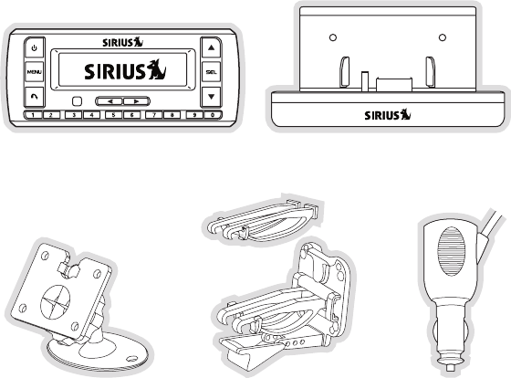
The following items are included with your purchase of the SIRIUS Stratus SV3 receiver:
Stratus SV3 ReceiverStratus SV3 Receiver Vehicle Docking StationVehicle Docking Station
Adhesive Dash MountAdhesive Dash Mount Vent Mount &
Extended Vent Hooks
Vent Mount &
Extended Vent Hooks
Cigarette Lighter
Adapter
Cigarette Lighter
Adapter
[ Package Contents ] 9
Satellite Radio Plug-n-Play Receiver
SIRIUS STRATUS
SV3 User Guide
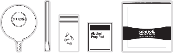
Unpack your SIRIUS Stratus SV3 receiver carefully and make sure that everything shown is
present. If anything is missing or damaged, or if your the receiver fails to operate, notify your
dealer immediately. It is recommended that you retain the original carton and packing materi-
als in case you need to ship your receiver in the future.
Antenna
Cover/Tail
Antenna
Cover/Tail
Alcohol
Swab
Alcohol
Swab
ScrewsScrewsMagnetic
Antenna
Magnetic
Antenna
User GuideUser Guide
[ Installation ]
10
Installation
Installation of your SIRIUS Stratus SV3 receiver is easy:
Choose a location in your vehicle where you will mount the receiver, either on the dash
or the vent.
Mount the receiver on the on the dash using the adhesive mount, or on the vent using
the vent mount.
Install the magnetic antenna on the roof of the vehicle, and route the antenna cable to
the receiver.
Connect the power cord for the receiver to your vehicle’s cigarette lighter.
Subscribe to the SIRIUS service and begin enjoying the SIRIUS entertainment!
Location
Choose a location in your vehicle where the receiver will not block your vision, interfere with
the vehicle controls, or obstruct the air bag. If you are using the adhesive mount, the location
should be suitable flat, smooth surface. The location should be easily reachable and provide
good visibility of the receiver.
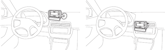
Figure 1 illustrates the dash mount option (A), and the vent mount option (B).
A. B.
1.
2.
3.
4.
5.
Figure 1Figure 1
[ Installation ] 11
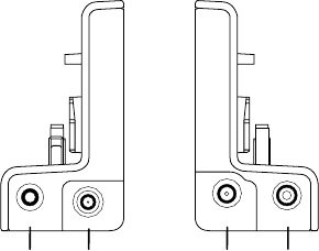
Mounting the Receiver
Attach the desired mounting device, dash or vent mount, to the vehicle docking station by
sliding the flat portion of the mount into the slot on the back top edge of the vehicle docking
station. Gently slide the mounting device in until it snaps into place.
Dash Mount Option (A)
If you choose the dash mount option, be sure to select your mounting position carefully. Once
the mount has been adhered to a surface, it will not be possible to remove it and adhere it
again.
Clean the selected mounting surface area in the vehicle with the alcohol swab. Unscrew the
adhesive foot from the mount. Peel the protective material off the adhesive on the foot and
press the foot firmly against the vehicle surface.
The adhesive mount should then be allowed to adhere for a minimum of 2-4 hours before use.
Best adhesion occurs after 24 hours.
Vent Mount Option (B)
To mount the vehicle dock using the vent mount option, install the vent mount as follows:
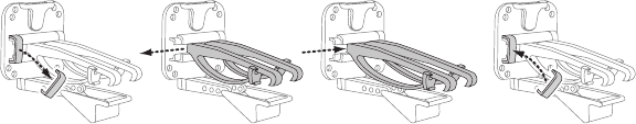
If the vent louvers in your vehicle are recessed, you may need to use the longer vent
hooks with the vent mount. Refer to Figure 2 and install the longer vent hooks into the
vent mount. Be sure to observe the orientation of the vent hooks as shown.
Slide Short
Vent Hooks Out
Remove
End Cap
Slide Extended
Vent Hooks In
Replace
End Cap
1.
Figure 2Figure 2
[ Installation ]
12
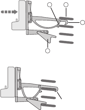
Refer to Figure 3 and attach the vent mount to a heating/air conditioning vent in your
vehicle. Position the two tension springs A against a vent louver B. Then push the vent
mount into the vent, far enough so that the hooks C drop down and hook the rear of the
vent louver (Figure 4). Once you are sure that the hooks have grasped a vent louver, the
tension springs A will keep the vent mount hooked to the louver.
C
B
A
D
PUSH
HOOKED
2.
Figure 3Figure 3
Figure 4Figure 4
[ Installation ] 13
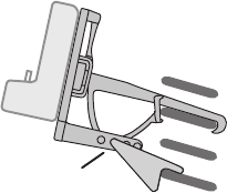
The angle of the docking station may be changed by changing the position of foot D on
the vent mount (Figure 3) to a different adjustment hole. (Figure 5)
A
DJUSTMENT HOLES
Installing the Antenna
The optimum mounting location for the magnetic antenna is on the roof of the vehicle, with a
minimum unobstructed area of 12 inches by 12 inches, and exactly 6½ inches from the rear
roof edge of the vehicle (the length of the rubber antenna cable cover/tail). It is important to
avoid any obstructions that will block the SIRIUS signal, obstructions such as a roof rack,
a sunroof, roof mounted cargo containers, or other antennas. For convertible vehicles, the
antenna should be installed on the trunk lid.
For best performance, it is recommended that the antenna be installed with the rubber
antenna cable cover/tail. This rubber antenna cable cover/tail provides two benefits: first, it
positions the antenna the recommended distance from the rear window, rear door/hatch, or
trunk edge to give the antenna the best view of the sky. Secondly, it conceals and protects
the exposed antenna cable. The rubber antenna cable cover/tail has adhesive strips that hold
it securely in place.
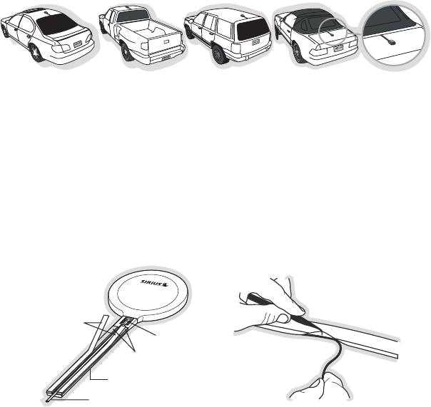
The following illustrations show the recommended mounting locations of the antenna for
several types of vehicles. (Figure 6) Follow these recommendations for best performance from
the antenna.
3.
Figure 5Figure 5
[ Installation ]
14
Sedan/Coupe. Mount the antenna along the rear center-line of the vehicle roof, located at the
rear of the roof near the rear window.
Pickup Truck. Mount the antenna along the rear center-line of the cab roof, located at the
rear of the roof near the rear window.
SUV/Mini-Van. Mount the antenna along the rear center-line of the vehicle roof, located at the
rear of the roof near the rear door/hatch.
Convertible. Mount the antenna along the center-line of the trunk lid, with the rubber antenna
cable cover/tail directed toward the rear window.
When you have selected a suitable mounting location, clean the area where the antenna and
rubber antenna cable cover/tail will be mounted with the supplied alcohol swab.
Rubber Antenna
Cover/Tail
Protective
Strips
Adhesive
Strain
Relief
Cable
Figure 7Figure 7
Figure 8Figure 8
figure 6figure 6
[ Installation ] 15
Connect the rubber antenna cable cover/tail to the antenna cable, making sure that the strain-
relief on the antenna sits into the rubber antenna cable cover/tail groove. (Figure 7) Route the
antenna cable through the wire channel in the rubber antenna cable cover/tail. Do not remove
the protective strips yet.
Temporarily position the antenna and rubber antenna cable cover/tail in the selected mounting
area and route the cable from the antenna to the vehicle’s interior by tucking it underneath the
rubber molding around rear window, as shown in Figure 8.
Route the cable from the lowest point of the rear window into the trunk. Take advantage of
any existing cable channels or wiring conduits. For SUVs, mini-vans and 5-door vehicles, bring
the cable into the vehicle under the rubber molding for the tailgate, and continue under the
interior trim.
From the trunk, or rear of the vehicle, route the cable around the passenger compartment and
to the front of the vehicle, to the receiver. Take care not pull the cable across sharp edges
that could damage it, and keep it away from areas where it might entangle feet. Coil any
excess antenna cable in a location where it can be hidden.
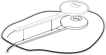
Once the antenna cable is routed through the vehicle, and you are satisfied with the cable
routing, peel the protective material from the adhesive strips and press the rubber antenna
cable cover/tail firmly into place on the vehicle. Double check that the location of the antenna
and rubber antenna cable cover/tail are correct, and continue to press firmly down on rub-
Figure 9Figure 9
[ Installation ]
16
ber antenna cable cover/tail for another 30 seconds. (Figure 9) At room temperature (68
degrees), maximum adhesion usually occurs within 72 hours. During this period, avoid car
washes and other contact with the antenna and rubber antenna cable cover/tail.
Connect the antenna cable to the ANT connection at the rear of the dock. (Refer to Figure 21
on page 23 for the location of this connector.)
Connecting the Cigarette Lighter Adapter
Connect the cigarette lighter power adapter to the receiver, and plug it into your vehicle.
(Refer to Figure 21 on page 23 for the location of this connector.)
Maximizing Audio Quality From Your SIRIUS Receiver
There are two primary ways to connect your SIRIUS satellite radio. The following procedures
will help you obtain the best performance.
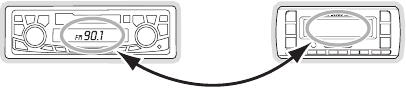
Wireless ConneCtion
Your SIRIUS radio contains an FM transmitter. The FM transmitter sends the audio from your
SIRIUS radio to your vehicle radio. (Figure 10)
90.1
To tune your transmitter:
Turn off your SIRIUS radio and tune through the FM channels on your vehicle radio to
locate an FM channel that is not broadcasting in your area. If you use an FM channel
that is being used by a local broadcaster, it will interfere with the performance of your
1.
Figure 10Figure 10

[ Installation ] 17
SIRIUS radio. Once you have located an FM channel that is not broadcasting in your
area, save it as a preset on your vehicle radio. This will become your SIRIUS preset.
Turn on your SIRIUS radio. Press and hold the Menu button to access the FM
channel number list on your SIRIUS radio. Tune to the channel that matches the SIRIUS
preset on your vehicle radio. Refer to the Menu Options/FM Frequency section of this
manual for more detailed instructions on how to do this.
Note: The FM transmitter in your SIRIUS radio is automatically set to FM channel 88.1. This
may not be the best channel in your area.
Tip: If you regularly travel between cities with different active FM channels, you may need
to find channels that are not broadcasting in each city. Several SIRIUS receiver models can
store multiple FM transmit channels, so you can easily switch to the best FM channel for
each city. You will also want to set the FM channels that are not broadcasting in each city as
presets on your vehicle radio.
If you’re not sure which FM channels are not broadcasting in your home or travel cities, you
can also go to http://SIRIUS.com/fmchannel and search for a suggested FM channel based
on your zip code.
DireCt ConneCtions
Direct connection provides better audio performance than a wireless connection and removes
the possibility of interference from local FM broadcasters.
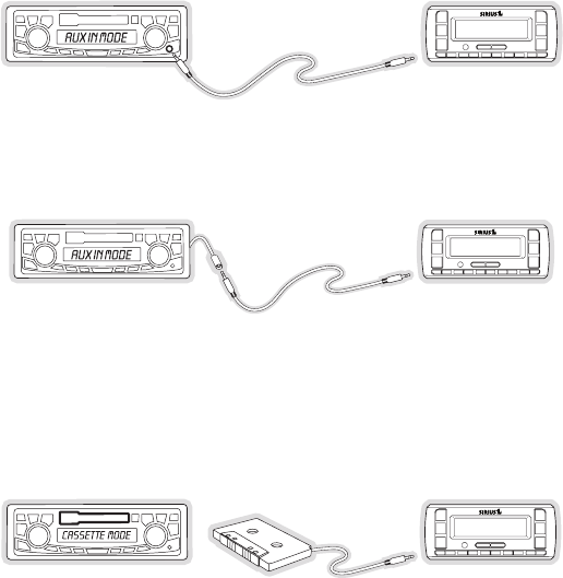
Direct Wired Audio Connection
If your vehicle radio offers an “AUX IN” or “LINE IN” connection, it is the best audio connec-
tion available. If the “AUX IN” or “LINE IN” connector is located on the front of your vehicle
radio, this is also the easiest connection. (Figure 11)
Purchase an audio cable that matches the connection type of your vehicle radio and your
SIRIUS radio at your local electronics retailer. Your SIRIUS radio requires a 1/8” stereo
male connector. Your local electronics retailer can help you determine the proper con-
nection for your car radio.
Plug one end of the cable into the AUDIO jack on your SIRIUS radio. (Refer to Figure 21
on page 23 for the location of this connector.) Plug the other end into your “AUX IN” or
“LINE IN” jack on your vehicle radio.
2.
1.
2.
[ Installation ]
18
FM OFF
NOTE: Refer to your vehicle radio manufacturer’s guidelines for correct installation.
NOTE: If the “AUX IN” or “LINE IN” connection is on the back of your vehicle radio, you may
want to consider professional installation. (Figure 12)
FM OFF
Cassette Adapter
If your vehicle radio has a cassette player:
Purchase a Cassette Adapter at your local electronics retailer.
Connect the adapter between the AUDIO jack on your SIRIUS radio (refer to Figure
21 on page 23 for the location of this connector) and the vehicle radio’s cassette slot.
(Figure 13)
FM OFF
NOTE: Refer to the cassette adapter manufacturer’s guidelines for correct use.
1.
2.
Figure 11Figure 11
Figure 12Figure 12
Figure 13Figure 13
[ Installation ] 19
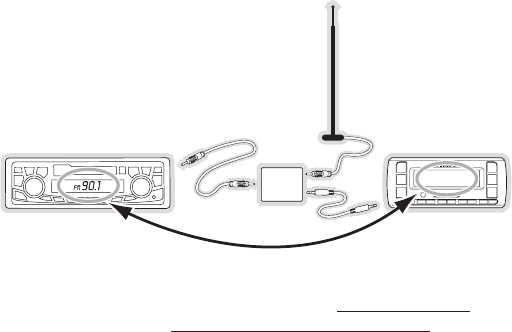
SIRIUS FM Direct Adapter
If your vehicle radio does not have an “AUX IN” or “LINE IN” jack, the SIRIUS FM Direct Adap-
tor provides a wired connection between your SIRIUS radio and your vehicle radio, eliminating
the outside static and interference you sometimes experience when using a wireless FM
connection. (Figure 14)
90.1
FM
DIRECT
ADAPTER
Professional installation may be required. See your local SIRIUS retailer. The SIRIUS FM
Direct Adaptor is available at your local SIRIUS retailer or at http://shop.sirius.com.
For the latest information refer to http://www.SIRIUS.com/vehicleinstallation.
Figure 14Figure 14
[ Installation ]
20
Subscribing to the SIRIUS Service
Before you can listen to the SIRIUS service, you need to subscribe to the SIRIUS Satellite
Radio service. To subscribe, do the following:
Be sure that the receiver is correctly installed, and that the antenna is oriented to receive
the SIRIUS signal.
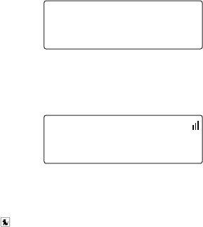
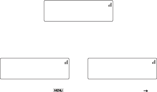
Turn on the receiver. After the startup sequence, it will update the SIRIUS channel line-
up. Wait until the channel updates have completed before pressing any buttons. (Figure
15)
Channel Updates
20% Completed
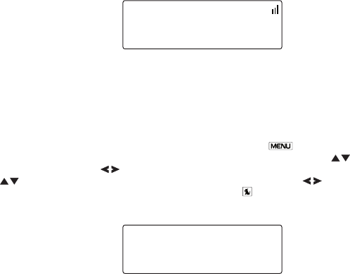
Once the channels have been updated, the display will change to
To Activate Call 1-888-539-SIRIUS and will tune to channel 184. (Figure 16) You will
not be able to listen to other channels until you activate your SIRIUS subscription.
To Activate Call
1-888-539-SIRIUS
184 Traf/Wx
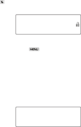
In order to subscribe, you will need your receiver’s unique 12-digit SIRIUS ID number
(SID). (Figure 17) You can display the SID by tuning to channel 000 by using the chan-
nel up/down buttons on receiver. You can also tune to channel 000 by momentarily
pressing the Select button, then entering 000 at the prompt. (The SID number is
also available on the receiver’s packaging.) Write the SID number down in the space
provided near the end of this user guide.
1.
2.
3.
4.
Figure 15Figure 15
Figure 16Figure 16

[ Installation ] 21
SID
123456789012
000 SiriusID
Have your credit card handy and contact SIRIUS on the Internet at:
https://activate.siriusradio.com/
and follow the prompts to activate your subscription. You can also call SIRIUS toll-free
at: 1-888-539-SIRIUS (1-888-539-7474).
When you have successfully subscribed to the SIRIUS service, and the receiver has
been updated with your subscription information, Sub Updated, Press Any Key will be
displayed. (Figure 18) To continue, press any key on the receiver.
Sub Updated
Press Any Key
184 Traf/Wx
You are now ready to begin enjoying SIRIUS Satellite Radio’s digital entertainment, and can
tune to other channels!
5.
6.
Figure 17Figure 17
Figure 18Figure 18
[ Controls ]
22
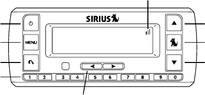
Controls
SIRIUS Stratus SV3 Reference Guide
Figure 1 and the section following identify and describe the buttons of the SV3 receiver.
1
2
3
4
5
6
8
7
6
Hank Williams, J
All My Rowdy Fri
019 BuzzSaw
Power Button: Turns the receiver’s power On and Off.
Menu Button: Used to access menu options to make setup and feature changes. Press-
ing and holding displays the FM Frequency menu option.
Jump Button: Jumps to a pre-selected traffic/weather channel.
Preset/Direct Tune Buttons (0-9): Sets and selects preset channels. Also used to
directly tune channels by entering the channel number.
Category Previous/Next Buttons: Navigates through the category (genre) list screen
which displays SIRIUS channel categories.
Channel Up/Down Buttons: Navigates through channels and display screens.
Select Button: Selects items highlighted on the display screen. When at the default
display screen, a press and release will display a prompt to enter a channel number.
Signal Strength Display: Displays the signal strength of the satellite signal.
1.
2.
3.
4.
5.
6.
7.
8.
Figure 1Figure 1
[ Controls ] 23
SIRIUS Stratus SV3 Docking Station Reference Guide
Figure 2 and the section following identify and describe the connectors of the SV3 receiver.
1 2 3 4
FM OUT ANT AUDIO
5VDC
FM OUT Connector: FM output for use with the optional FM Direct Adapter.
ANT Antenna Connector: Connection for the provided magnetic antenna.
DC5V Power Connector: Power connection for the cigarette lighter adapter.
AUDIO OUT Connector: Optional audio output connection for connecting to your
vehicle’s audio system if you are not using the FM transmitter.
1.
2.
3.
4.
Figure 2Figure 2
[ Operation ]
24
Operation
Display Screen Information
When you have successfully activated your SIRIUS subscription, and the receiver has re-
ceived the subscription information from the SIRIUS signal, the default display screen will be
displayed. (Figure 1)
Artist Name
Song Title
001 Channel
When the receiver is powered on, the previously selected channel will automatically begin
playing.
You can select to have the channel name (Figure 1), category name (Figure 2), or time (Figure
3) displayed on the default display screen.
Elvis Presley
One Night
013 Pop
Elvis Presley
One Night
013 10:49
To change the display, press the Menu button, then select Display Options Mode
and choose the desired display option.
Figure 1Figure 1
Figure 2Figure 2
Figure 3Figure 3
[ Operation ] 25
Changing Channels and Categories
Pressing the Channel Up/Down buttons will cause the receiver to immediately tune to
the next or previous channel.
Pressing the Category Previous/Next buttons will cause the receiver to display a catego-
ry and a list of channels in the category. (Figure 4) Use the Channel Up/Down buttons to
navigate through the list, and press the Select button to choose a selected channel.
>001 Sirius Hits
002 StarLite
Pop
Use the Category Previous/Next buttons to scroll through the categories. (Figures 5 & 6)
>014 Classic Vin
015 Classic Rew
Rock
>033 Area 33
034 Boombox
Elec/Dnc
Figure 4Figure 4
Figure 5Figure 5
Figure 6Figure 6

[ Operation ]
26
Selecting Channels Directly
A channel may be directly selected by entering the channel number using 0-9 buttons on the
receiver.
To enter a channel number, momentarily press and release the Select button. At the display
prompt (Figure 7), enter the three digit channel number.
Enter Channel
# ___
031 Margvlle
Channel Presets
You can store up to 10 of your favorite channels as presets for quick recall access by press-
ing the 0–9 buttons.
Storing Channel Presets
To store a favorite channel as a preset, do the following:
Tune the receiver to the channel you wish to store as a preset.
Press and hold for 1 second the numbered preset button (0–9) in which you wish to
store your favorite channel. An audible beep will be heard and the preset number you
selected will then be displayed to confirm that the channel has been stored. (Figure 8)
P3 Stored
072 PureJazz
Note: If the preset button already has a channel stored in it, the preset will be replaced by the
newly stored channel.
1.
2.
Figure 7Figure 7
Figure 8Figure 8
[ Operation ] 27
Selecting Presets
Press and release one of the 0–9 buttons to select a preset channel. If no channel has been
saved in the selected preset, the PRESET EMPTY message will be displayed. (Figure 9)
Preset Empty
035 Chill
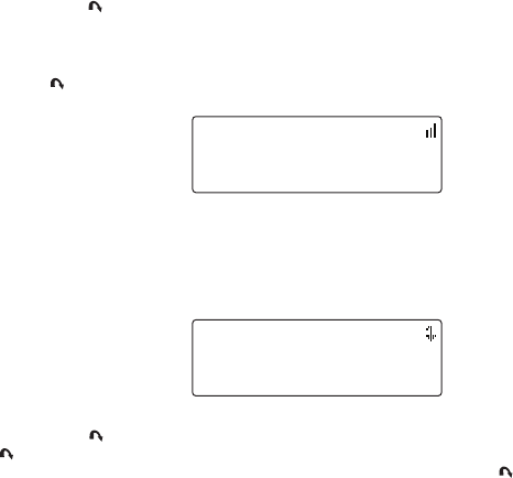
FM Frequency
When the FM transmitter in your SIRIUS receiver is turned on, an FM radio tuned to the same
FM frequency as your SIRIUS receiver will receive the SIRIUS audio.
To quickly access the FM frequency menu, press and hold the Menu button. The current
FM frequency is displayed. (Figure 10) To change the FM frequency, use the Channel
Up/Down buttons and Category Previous/Next buttons to adjust the FM frequency. The
Category Previ-
ous/Next buttons adjust in 1 MHz increments. Press the Select button to set the new FM
frequency.
88.1 MHz
FM Frequency
Note: The FM frequency is 88.1 MHz by default. This frequency may not be suitable for your
area.
Figure 9Figure 9
Figure 10Figure 10
Channel Up/Down buttons adjust in 0.2 MHz increments and the
[ Operation ]
28
Jump Button
Pressing the Jump button will jump to a traffic/weather channel which you have chosen for
your area. This button allows you to quickly tune the traffic/weather for your area and then
tune back to the original channel by pressing the button again. (Figure 11)
Refer to the Jump Settings section in the Menu Options section for information on configur-
ing the Jump button for traffic/weather in your area.
Jump to NYC
022 1st Wave
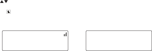
If your traffic/weather report is not immediately available, the display will indicate that a
jump is pending. (Figure 12) Once your local traffic/weather report is ready, the receiver will
automatically tune to the traffic/weather channel. You may have to wait a few minutes for your
desired report.
NYC Pending
022 1st Wave
Pressing the Jump button while a jump is pending will cancel the jump. Pressing the
Jump button after the receiver has tuned to the traffic/weather report will return to the
channel to which you had been listening immediately prior to pressing the Jump button.
Figure 11Figure 11
Figure 12Figure 12
[ Operation ] 29
Channel Lock
Channels may be locked so that they can only be accessed by entering a 4-digit code. Chan-
nels which have been locked will not appear in the channel lists, and cannot be selected using
the Channel Up/Down buttons.
Locked channels can only be selected by using the direct entry method, by momentarily press-
ing the Select button and entering the channel number at the prompt by using the 0–9
buttons. (Figure 13) You will then be prompted to enter the 4-digit channel lock code before
you can access the channel. (Figure 14)
Enter Channel
# ___
031 Margvlle
# ____
Enter Code
For more information on how to set the channel lock code, and how to lock or unlock chan-
nels, refer to the Channel Lock section on page 36.
Figure 13Figure 13
Figure 14Figure 14
[ Menu Options ]
30
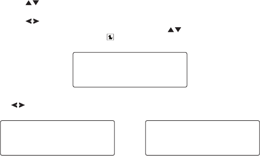
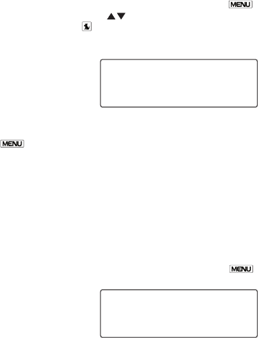
Menu Options
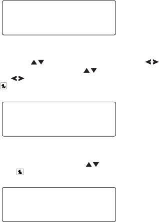
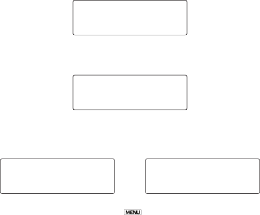
To enter the Menu Options page of the receiver, press the Menu button. (Figure 1) To
select a menu option, use the Channel Up/Down buttons to display the option you wish
to adjust, and press the Select button. If a selection is not made within 10 seconds, the
receiver will exit the menu options mode, and revert to the last active display mode.
>Sirius ID
FM Transmitter
Menu Options
To exit menu options, or any of the other menu option screens, repeatedly press and release
thee Menu button until you are returned to the default display screen.
The following sections explain each of the menu options in the order in which they are dis-
played on the Menu Options screen.
SIRIUS ID
The Sirius ID menu option displays your 12 digit Sirius ID (SID) number. (Figure 2) The SID is
unique to every receiver and is required to activate your service. It is recommended that you
write this number in the space provided near the end of this user guide. No adjustments are
allowed in this mode. To exit the Sirius ID menu, press the Menu.
123456789012
Sirius ID
Figure 1Figure 1
Figure 2Figure 2
[ Menu Options ] 31
FM Transmitter
The FM Transmitter menu option provides for turning the FM transmitter On and Off, and
changing the FM frequency which the receiver will broadcast on. (Figure 3) By default, the FM
transmitter is on and the FM frequency is set to 88.1 MHz. This frequency may not be suitable
for your area.
>FM Frequency
FM On/Off
FM Transmitter
FM Frequency
To change the FM frequency, use the Channel Up/Down buttons and Category
Previous/Next buttons to adjust the FM frequency. The Channel Up/Down buttons adjust
Category Previous/Next buttons adjust in 1 MHz incre-
ments. (Figure 4) Press the Select button to set the new FM frequency.
88.1 MHz
FM Frequency
FM On/Off
To turn the receiver’s FM transmitter On or Off, use the Channel Up/Down buttons to
select your choice and press the Select button. (Figure 5)
>On
Off
FM On/Off
Figure 3Figure 3
Figure 4Figure 4
Figure 5Figure 5
in 0.2 MHz increments and the
[ Menu Options ]
32
Settings
The Settings menu provides for changing the brightness and contrast of the display screen,
and the display mode of the display screen. (Figure 6)
>Brightness
Contrast
Display Options
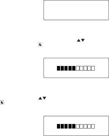
Brightness
The Brightness menu option adjusts the overall intensity of the LCD display to help with
viewing in different lighting conditions. Use the Channel Up/Down buttons to adjust the
brightness and press the Select button to set your choice. (Figure 7) The bar graph will
move to indicate the change.
- +
Brightness
Contrast
The Contrast menu option adjusts the relationship between the background and the text on
the LCD display. Use the Channel Up/Down buttons to adjust the brightness and press
the Select button to set your choice. (Figure 8) The bar graph will move to indicate the
change.
- +
Contrast
Figure 6Figure 6
Figure 7Figure 7
Figure 8Figure 8
[ Menu Options ] 33
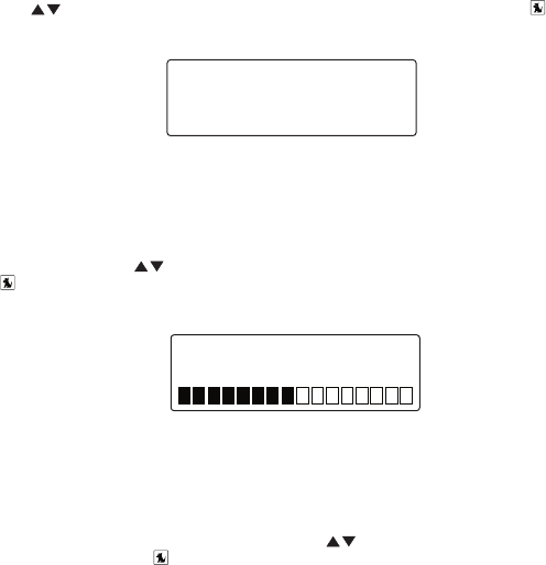
Mode
The Mode menu option provides for changing the default display screen to display either the
channel name, category name, or time. Refer to the Display Screen Information section on
page 24 for examples.
Use the Channel Up/Down buttons to select the desired mode and press the Select
button to set your choice. (Figure 9)
>Channel Name
Category Name
Mode
Audio Level
The Audio Level menu option adjusts the level of the audio output of the receiver. To adjust
the audio level, use the Channel Up/Down buttons to change the audio level and press
the Select button to set your choice. (Figure 10). The bar graph will move to indicate the
change.
-
+
Audio Level
Tones
The Tones menu option is for selecting whether an audio tone will be heard as you navigate
menus and lists. To turn the tones on or off, use the Channel Up/Down buttons to select
your choice and press the Select button to set your choice. (Figure 11).
Figure 9Figure 9
Figure 10Figure 10

[ Menu Options ]
34
>On
Off
Tones
Clock
The Clock menu option provides for adjustment of the clock format, the time zone, and day-
light savings time function. (Figure 11)
The time data for the receiver’s clock is provided via the SIRIUS signal, and will update based
on the data received from the signal.
>Format
Time Zone
Clock
Format
The Format menu option is for changing the clock display format of the receiver to 12 hour
or 24 hour format. Use the Channel Up/Down buttons to select the desired format and
press the Select button to set your choice. (Figure 12)
>12 Hour
24 Hour
Format
Figure 11Figure 11
Figure 11Figure 11
Figure 12Figure 12
[ Menu Options ] 35
Time Zone
The Time Zone menu option is for changing the time zone of the receiver. Use the Chan-
nel Up/Down buttons to select the desired time zone and press the Select button to set
your choice. (Figure 13)
>Eastern
Atlantic
Time Zone
Daylight Savings Time
The Daylight Savings Time menu option is for turning the Daylight Savings Time feature On
or Off. Use the Channel Up/Down buttons to select on or off and press the Select
button to set your choice. (Figure 14)
>Yes
No
DST Observed
Jump Settings
The Jump menu option is used to select a city for Traffic and Weather reports when the
Jump button is pressed. Use the Channel Up/Down buttons to select a city and press
the Select button to set your choice. (Figure 15)
DC
>NYC
Choose Traffic
Figure 13Figure 13
Figure 14Figure 14
Figure 15Figure 15

[ Menu Options ]
36
Channel Lock
The Channel Lock menu option provides the ability to lock out with password protection any
channels you do not want others to access without your permission. A locked channel will not
appear in the channel list.
When access to a locked channel is attempted using the direct channel entry method, the
Enter Code screen is displayed and the channel cannot be accessed until the correct code is
entered.
Lock/Unlock
The Lock/Unlock menu option is used for selecting specific channels to either lock or unlock.
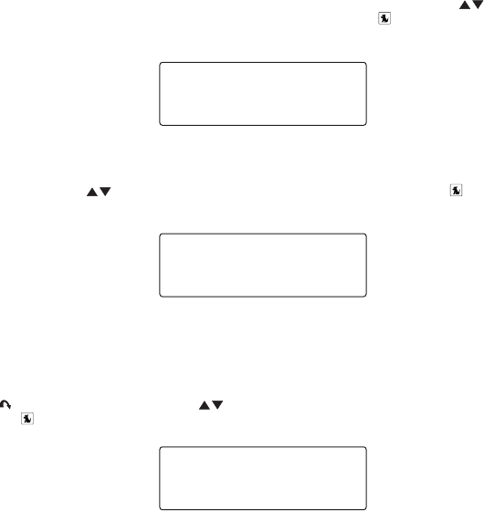
To lock or unlock a channel:
If this is the first time that Channel Lock is being used, you will be prompted to create
and enter a four digit numerical code. (Figure 16) This code can be any four digit num-
ber from 0000 to 9999. Then you will be prompted again to confirm the code you just
entered. (Figure 17) If you should exit this prompt without entering a code, you will be
prompted to set a code next time you enter the Lock/Unlock menu option.
# ____
New Code
# ____
Confirm Code
If a code has been previously set, the Enter Code prompt will be displayed. Enter your
four digit code and press the Select button to continue. (Figure 18)
# ____
Enter Code
When the correct code has been entered, a you will enter a list of channels. Use the
Channel Up/Down buttons to navigate to the channel you wish to lock or unlock,
1.
2.
Figure 16Figure 16
Figure 17Figure 17
Figure 18Figure 18
[ Menu Options ] 37
and press the Select button. A locked channel will have the lock icon displayed to the
right of the channel number and name. (Figure 19)
>108 Maxim
110 Court TV
Lock/Unlock
You can continue to select channels for locking or unlocking until you are finished. To exit the
Lock/Unlock menu option press the Menu button.
Edit Code
The Edit Code menu option is used to change a previously selected channel lock code. (The
first time the Edit Code menu option is selected you will be prompted to enter a four digit
code as described in the previous section.) (Figures 16 & 17)
To edit the channel lock code:
At the prompt, enter the current four digit channel lock code. (Figure 20) If you do not
enter the correct code, a message will be displayed alerting you that the wrong code
was entered (Figure 24), and you will be prompted again to enter the code again. (If you
have forgotten your Parental Control code, call SIRIUS Customer Service for help.)
# ____
Enter Code
When the correct code is entered, you will be prompted to enter the new channel lock
code. (Figure 21)
1.
2.
Figure 19Figure 19
Figure 20Figure 20
[ Menu Options ]
38
# ____
New Code
You will then be prompted to confirm the new channel lock code by entering it again.
(Figure 22)
# ____
Confirm Code
If you confirmed the correct channel lock code, a confirmation screen is displayed.
(Figure 23) If you entered the wrong code, you will be alerted and you will have to repeat
the process again. (Figure 24)
Code Saved
Confirm Code
Wrong Code
Confirm Code
To exit the Edit Code menu option press the Menu button.
3.
4.
Figure 21Figure 21
Figure 22Figure 22
Figure 23Figure 23
Figure 24Figure 24

[ Menu Options ] 39
Signal
The Signal menu option provides a visual display of the strength of the SIRIUS signal from the
satellite antenna and also from terrestrial (ground) transmitters. (Figure 25)
SAT - +
TER - +
Signal
To exit the Signal menu option press the Menu button.
Factory Default
The Factory Default menu option will restore most every feature of the receiver to the original
factory settings. The following is a list of all features affected by the Factory Default option:
All Presets are cleared
Receiver set to Normal Tuning Mode
Display brightness set to 50%
Display Contrast set to 50%
FM Transmitter set to On
FM Frequency set to 88.1 MHz
Jump setting is cleared
Top line display mode set to Channel Name
Audio level set to -3db
Confirmation Tone set to On
Note that the Channel Lock feature is not affected by the Factory Default option. If a code
has been set for the channel lock, the code will not be reset by the Factory Default feature,
preventing circumvention of the channel lock feature. Channels which have been locked will
remain locked.
•
•
•
•
•
•
•
•
•
•
Figure 25Figure 25

[ Menu Options ]
40
When you perform a Factory Default, you will be prompted twice to confirm that you really
want to proceed. (Figures 26 & 27)
Yes
>No
Restore?
Yes
>No
Are You Sure?
If you choose to proceed, the receiver will confirm that the factory defaults are being restored.
(Figure 28) When the Factory Default is complete, the receiver will display Call 1-888-539-
SIRIUS to Subscribe, the preview channel. The receiver is still subscribed to the SIRIUS
service.
Restoring
Figure 26Figure 26
Figure 27Figure 27
Figure 28Figure 28

[ Troubleshooting ] 41
Troubleshooting
Symptom Solution
Receiver does not
power on
Blown fuse, or the power cable is not properly connected.
Check for a bad fuse and check power cable connection
Receiver displays: No
Antenna
The satellite antenna is not connected to the receiver.
Check the satellite antenna connection to the receiver.
Receiver displays:
Acquiring Signal
No satellite signal is being received.
Check for obstacles over or around the satellite antenna.
Change the vehicle location to eliminate nearby obstacles
(bridges, overpasses, tress, buildings, etc.).
Audio static or loss of
clarity
The FM frequency contains static.
Locate a quiet FM frequency on your vehicle radio and set the FM
transmitter frequency of the receiver to match.
If using the AUDIO OUT connector, check the cable connections.
No sound The audio cables are not connected, or the FM radio is set to the
wrong frequency. Check the audio cables at the receiver and the
radio. Tune the FM radio to the same FM frequency the receiver
is tuned.
[ Specifications ]
42
Specifications
Satellite Frequencies . . . . . . . . . . . . . . . . . . . . . . . . . . . . . . . . . . . . . .2322.293/2330.207 MHz
Terrestrial Frequencies .............................................2326.250MHz
Receiver Power Requirements. . . . . . . . . . . . . . . . . . . . . . 4.9–5.6 Volts, Negative Ground, DC
Cigarette Lighter Adapter Power Requirements . . . . . . . . . . 9–16 Volts, Negative Ground, DC
Audio Output ............................................550mVrms (+/- 50mVrms)
Total Harmonic Distortion (THD)............................................<0.2%
Signal-to-noise (S/N)........................................... Greater than 73dB
Fuse Requirement ......................................................2A ATC
Receiver Dimensions (Length x Width x Depth) . . . . . . . . . . . 114.3mm x 48.26mm x 15.24mm
(4.5” x 1.9” x 0.6”)
Receiver Weight...................................................85.0g (3.0 oz.)
Antenna Type............................................... Low Profile Magnetic
Antenna Cable Length . . . . . . . . . . . . . . . . . . . . . . . . . . . . . . . . . . . . . . .21’ (single micro-cable)
Connector Type ................................................ SMB (right-angle)
Audio Interface...........................................1/8” / 3.5mm Stereo Jack
FM Out Interface ....................................................2.5mm Jack
Note: Features and Specifications are subject to change without notice.
[ Warranty ] 43
Warranty
12 Month Warranty
SIRIUS Satellite Radio Inc. (the “Company”) warrants to the original retail purchaser of this product
that should this product or any part thereof, under normal use and conditions, be proven defective in
material or workmanship within 12 months from the date of original purchase, such defect(s) will be
repaired or replaced with new or reconditioned product (at the Company’s option) without charge for
parts and repair labor. To obtain repair or replacement within the terms of this Warranty, the product
is to be delivered with proof of warranty coverage (e.g. dated bill of sale), specification of defect(s),
transportation prepaid, to the location shown below under WARRANTY RETURN.
This Warranty does not extend to the elimination of externally generated static or noise, to correction
of antenna problems, to costs incurred for installation, removal or reinstallation of the product, or to
damage to tapes, compact discs, speakers, accessories, or vehicle electrical systems.
This Warranty does not apply to any product or part thereof which, in the opinion of the Company,
has suffered or been damaged through alteration, improper installation, mishandling, misuse, neglect,
accident, or by removal or defacement of the factory serial number/bar code label(s). THE EXTENT
OF THE COMPANY’S LIABILITY UNDER THIS WARRANTY IS LIMITED TO THE REPAIR OR
REPLACEMENT PROVIDED ABOVE AND, IN NO EVENT, SHALL THE COMPANY’S LIABILITY
EXCEED THE PURCHASE PRICE PAID BY PURCHASER FOR THE PRODUCT.
This Warranty is in lieu of all other express warranties or liabilities. ANY IMPLIED WARRANTIES, IN-
CLUDING ANY IMPLIED WARRANTY OF MERCHANTABILITY, SHALL BE LIMITED TO THE DURA-
TION OF THIS WRITTEN WARRANTY. ANY ACTION FOR BREACH OF ANY WARRANTY HERE-
UNDER INCLUDING ANY IMPLIED WARRANTY OF MERCHANTABILITY MUST BE BROUGHT
WITHIN A PERIOD OF 48 MONTHS FROM DATE OF ORIGINAL PURCHASE. IN NO CASE SHALL
THE COMPANY BE LIABLE FOR ANY CONSEQUENTIAL OR INCIDENTAL DAMAGES FOR
BREACH OF THIS OR ANY OTHER WARRANTY, EXPRESS OR IMPLIED, WHATSOEVER. No
person or representative is authorized to assume for the Company any liability other than expressed
herein in connection with the sale of this product. Some states do not allow limitations on how long
an implied warranty lasts or the exclusion or limitation of incidental or consequential damage so the
above limitations or exclusions may not apply to you. This Warranty gives you specific legal rights and
you may also have other rights which vary from state to state.
WARRANTY RETURN: To obtain repair or replacement within the terms of this Warranty, please re-
turn product to an authorized retailer or call Customer Service at 1-800-869-5590; proof of purchase
and description of defect are required. Products to be returned to an approved warranty station must
be shipped freight prepaid.

[ SIRIUS ID ]
44
SIRIUS ID
Write down the SIRIUS ID (SID) of your SIRIUS Stratus SV3 in the space provided below.
SID: _______________________________________

SIRIUS Customer Service: 1-888-539-7474
customercare@sirius-radio.com
SIRIUS Satellite Radio Inc.
1221 Avenue of the Americas
New York, NY 10020
1-888-539-7474
http://www.sirius.com

SIRIUS Satellite Radio Inc.
1221 Avenue of the Americas
New York, NY 10020
(800) 869-5590
http://sirius.com
SIRIUS Stratus SV3 (081906a)
49.UPASV.001