Wistron NeWeb VWL10 Cantenna User Manual UserMan NKR VWL10
Wistron NeWeb Corporation Cantenna UserMan NKR VWL10
UserMan_NKR-VWL10
CA10002
User’s Manual
This document provides instructions for installing the antenna and describes the requirements
and specifications of this product. The antenna can be mounted on a vertical or horizontal
surface, or on a slope. Read this document carefully before installing to ensure your safety and
product performance.
Contents
FEDERAL COMMUNICATION COMMISSION (FCC) INTERFERENCE STATEMENT ............ 3
BEFORE YOU START .................................................................................................... 3
IMPORTANT SAFETY INSTRUCTIONS .......................................................................... 3
UNPACKING INFORMATION ........................................................................................ 5
WIRING PLAN ............................................................................................................. 6
SELECTING AN INSTALLATION LOCATION .................................................................. 6
INSTALLING THE CANTENNA ...................................................................................... 7
LED INDICATORS ...................................................................................................... 11
PRODUCT SPECIFICATIONS ...................................................................................... 11
Federal Communication Commission (FCC)
Interference Statement
This equipment has been tested and found to comply with the limits for a Class B digital device,
pursuant to Part 15 of the FCC Rules. These limits are designed to provide reasonable
protection against harmful interference in a residential installation. This equipment generates,
uses and can radiate radio frequency energy and, if not installed and used in accordance with
the instructions, may cause harmful interference to radio communications. However, there is
no guarantee that interference will not occur in a particular installation. If this equipment does
cause harmful interference to radio or television reception, which can be determined by turning
the equipment off and on, the user is encouraged to try to correct the interference by one of
the following measures:
- Reorient or relocate the receiving antenna.
- Connect the equipment into an outlet on a circuit different from that to which the
receiver is connected.
- Consult the dealer or an experienced radio/TV technician for help.
- Install an approved low pass filter
FCC Caution: Any changes or modifications not expressly approved by the party responsible for
compliance could void the user's authority to operate this equipment.
This device complies with Part 15 of the FCC Rules. Operation is subject to the following two
conditions: (1) This device may not cause harmful interference, and (2) this device must accept
any interference received, including interference that may cause undesired operation.
Radiation Exposure Statement:
This equipment complies with FCC radiation exposure limits set forth for an uncontrolled
environment. This equipment should be installed and operated with minimum distance 20cm
between the radiator & your body.
Before You Start
Carefully follow the warnings and safety notices in this manual. Please pay special attention to
the following indications of potentially hazardous situations:
Warning:
Indicates a hazardous situation, which, if not avoided, could result in serious injury or even
death.
Caution:
Indicates a situation, which, if not avoided, could damage this product or other devices.
Note:
Indicates additional information to alert the user to possible issues and to help the user
understand, use and maintain the product.
Important Safety Instructions
Caution:
These servicing instructions are for use by qualified service personnel only. To reduce the risk of
electric shock do not perform any servicing other than that contained in the operating
instructions unless you are qualified to do so.

Warning:
For your safety, follow these important safety precautions:
1) Read these instructions.
2) Keep these instructions.
3) Heed all warnings.
4) Follow all instructions.
5) Do not use this unit near water.
6) Clean only with dry cloth.
7) Do not block any ventilation openings. Install in accordance with the manufacturer’s
instructions.
8) Do not install near any heat sources such as radiators, heat registers, stoves, or other
apparatus (including amplifiers) that produce heat.
9) Do not defeat the safety purpose of the polarized or grounding-type plug. A polarized plug
has two blades with one wider than the other. A grounding type plug has two blades and a
third grounding prong. The wide blade or the third prong are provided for your safety. If
the provided plug does not fit into your outlet, consult an electrician for replacement of the
obsolete outlet.
10) Protect the power cord from being walked on or pinched particularly at plugs, convenience
receptacles, and the point where they exit from the unit.
11) Only use attachments/accessories specified by the manufacturer.
12) Use only with the cart, stand, tripod, bracket, or table specified by the manufacturer, or
sold with the unit. When a cart is used, use caution when moving the cart/unit
combination to avoid injury from tip-over.
13) Unplug this unit during lightning storms or when unused for long periods of time.
14) Refer all servicing to qualified service personnel. Servicing is required when the unit has
been damaged in any way, such as power-supply cord or plug is damaged, liquid has been
spilled or objects have fallen into the unit, the unit has been exposed to rain or moisture,
does not operate normally, or has been dropped.
Warning:
When installing the product, you must take extreme care not to come into contact with electric
power lines. You risk serious injury or even death if the product is located near overhead
power lines, electric lights or power circuits. Be sure to maintain a safe distance before you
start any installation procedures. We recommend that you maintain a minimum distance of 20
feet (about 6 meters) from all power lines.
If any part of the product comes into contact with a power line, stay away from the product and
all its related components. DO NOT REMOVE IT YOURSELF. Call your local power company for
assistance.
Warning:
For your personal safety, follow these important safety precautions:
1. Do not install the product on a wet or windy day.
2. Perform as many of the installation procedures as possible on the ground.
3. When installing the product, if you accidentally drop any part of it, do not try to catch it. Let
it fall.
4. Installation of the product is usually performed by two or more people. Ensure that all
participants are well-trained and understand the tasks that they are assigned.
5. Do not use a metal ladder, or if you do make sure it has rubber feet installed. Metal ladders
can be deadly as they conduct electricity.
6. Wear shoes with rubber soles.
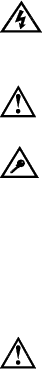
Unpacking Information
Thank you for purchasing
this product. Before
installation, please confirm
you have collected all
required items:
Note: Not all
accessories are included
inside one the same carton.
Consult your dealer if any of
them are missing.
The Cantenna
Cantenna pedestal
Cantenna Mounting plate
Screw pack 1:
5/16”-18UNCx15mm (4PCS)
Screw pack 2:
#10-32UNF*1/2" L FLANGE (1PCS)
825A807624-S 5/16"-9T*3” (2PCS)
825A805124-S 5/16"-9T*2” (4PCS)
Power Inserter
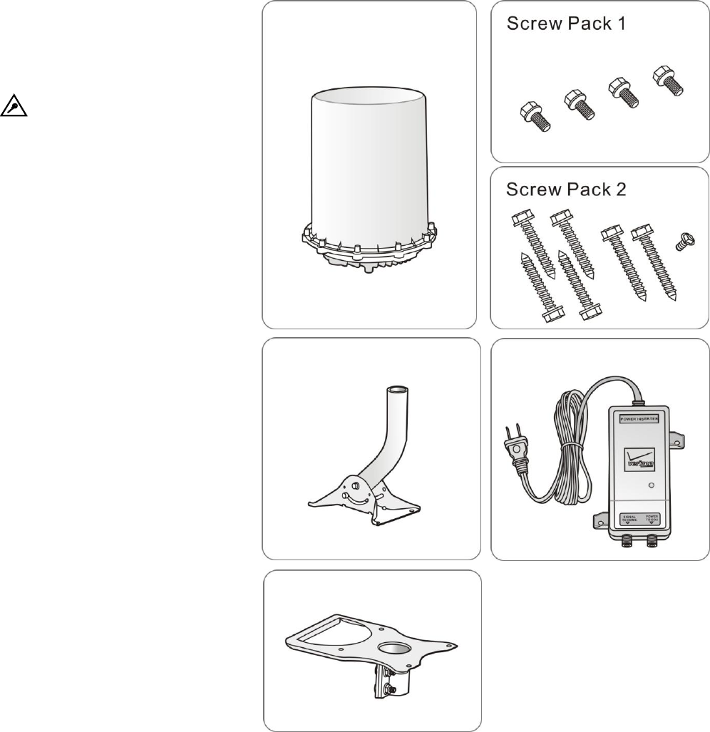
Wiring Plan
Basic connection:
In this example, the Cantanna
connects directly to the power
inserter and then to the Home
Service Gateway without
connecting home coaxial
network.
Selecting an Installation Location
The product is designed to be installed vertically on a flat surface. The surface can be horizontal,
vertical or a slope. See following notes before choosing an installation location:
Note:
Ensure that there is enough space for adjusting the antenna angles.
Antenna performance could be influenced by nearby obstacles, especially metal objects
and meshes.
Install the antenna away from wireless devices that operates in 700 GHz. Those devices
may cause signal interference due to operating in the same frequencies.
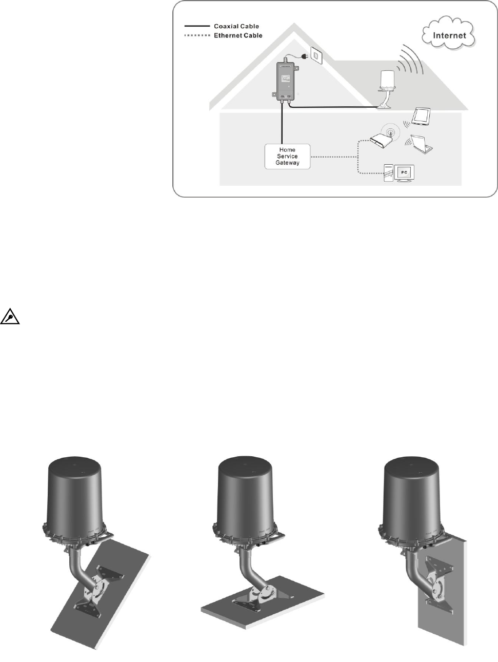
Installing the Cantenna
1. With the protection pulp, take the product out of the box. Place the product upside down on
a flat surface
2. Install the mounting plate with the product using the 4
screws in screw pack 1 (5/16” 18UNCx15mm.) Fully tighten
the four screws.
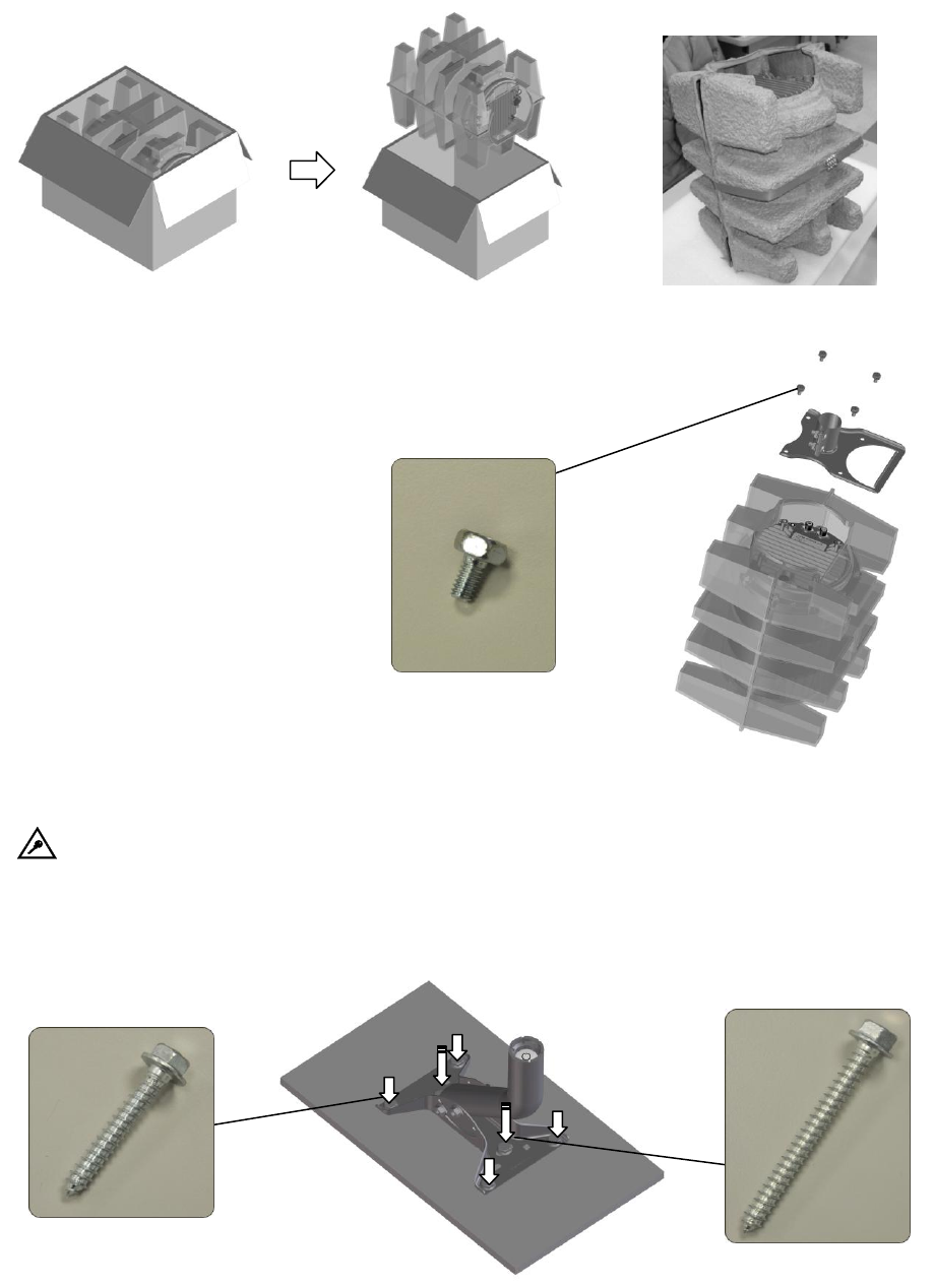
3. Install the pedestal to the location you selected using the screws in screw pack 2.
Note: 825A807624-S 5/16"-9T*3” (2PCS) and 825A805124-S 5/16"-9T*2” (4PCS)
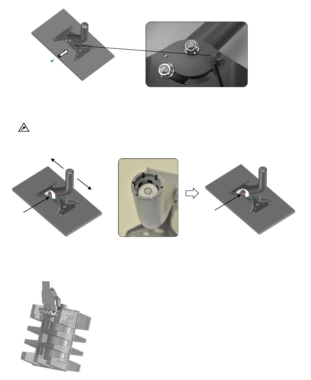
4. Tighten the grounding screw and securely ground the wire.
5. Adjust the angle of the pedestal mast. Use the spirit level and confirm the bubble is
perfectly located at the center position. Fully tighten the mast screws after confirming the
mast angle.
Note: You may also need to fine-tune the height of the pedestal screws that you
installed in step3 for obtaining a perfectly horizontal position.
6. Grip the mounting plate and take the product to the installation location.
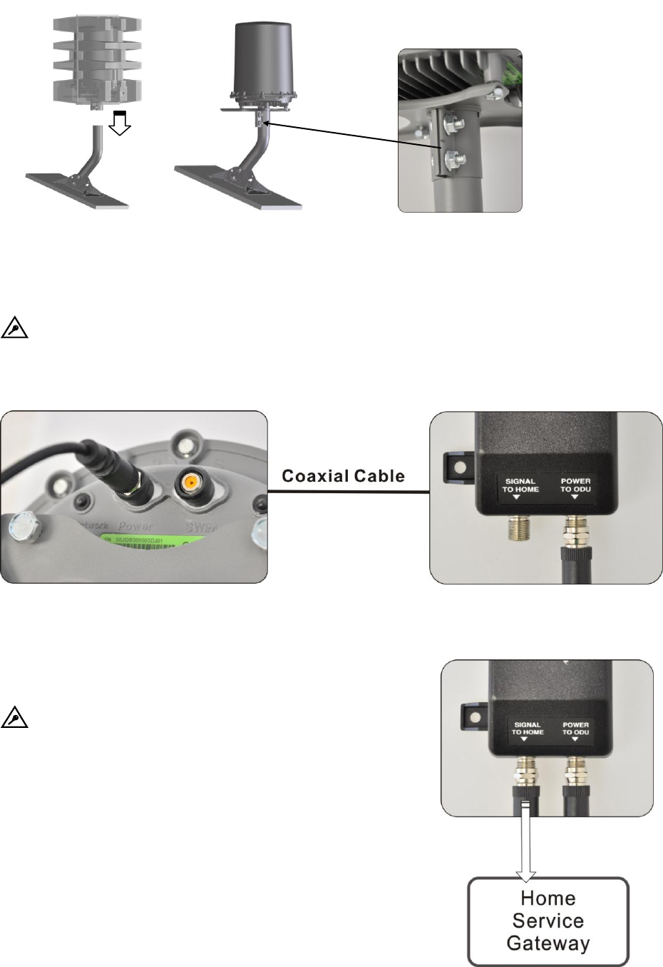
7. Attach the Cantenna to the pedestal and remove the protection pulp. Tighten the 2 bolts on
the mounting plate.
8. Connect one end of a coax cable to the Power port of the Cantenna. Run the cable from
the Cantenna to the power inserter and attach the cable to the “POWER TO ODU” port of
the power inserter.
Note: This step demonstrates the basic connection method. You can also choose to
attach the coax cable from the Cantenna to your home coaxial network first, and then
attach the power inserter to your home coaxial network in some other locations.
9. Connect a coaxial cable from the SIGNAL TO HOME port
of the power inserter to your home service gateway.
Note: If you have attached the Cantenna to your
home coaxial network instead of connecting it to the
power inserter directly, skip this step and attach the home
service gateway to your coaxial network directly.
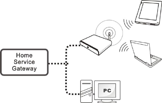
10. Plug the power inserter to a wall power socket.
11. Connect your Ethernet compatible devices to the home
service gateway for accessing the Internet.
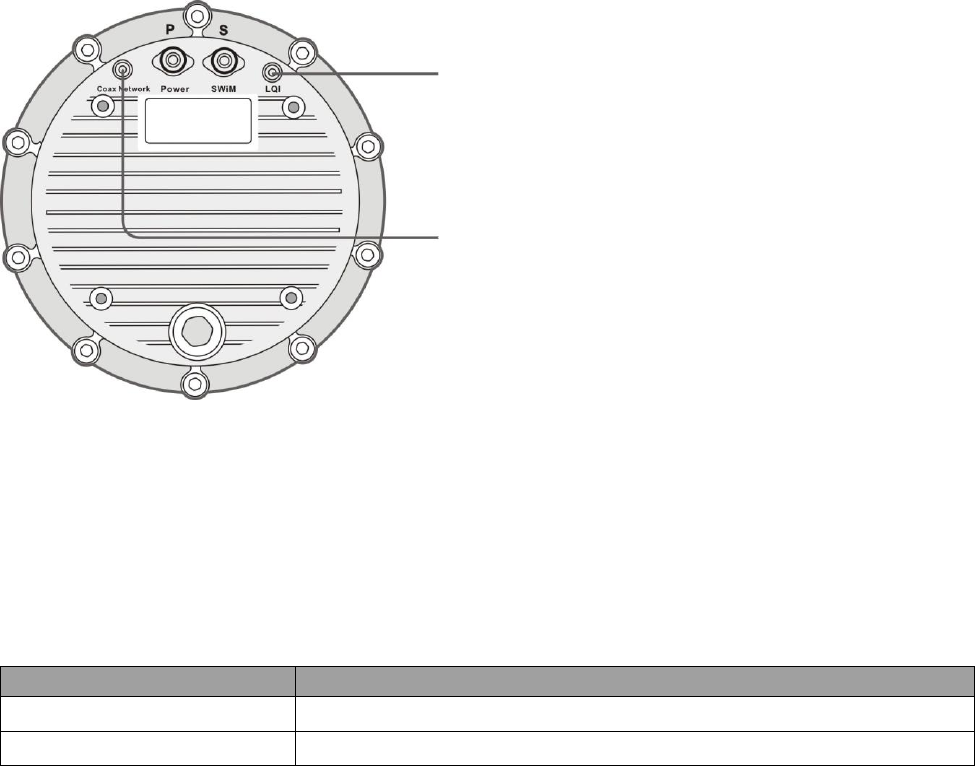
LED Indicators
Product Specifications
Items
Description
Power Input
DC 15~20.5V, 1.2A
Operating Temperature
60 degree C
LQI
Red: Low LTE signal strength
Blue: Medium LTE signal stregth
Green: High LTE signal strength
Coax Network
Red: Power supply connected
Green: Valid connection to Home service
gateway.