Wistron NeWeb WLD71-T3 LTE Router User Manual
Wistron NeWeb Corporation LTE Router
User manual

WLD71-T3 LTE Router
User Manual

1
Safety Precautions
Please read this user’s manual before operating this product.
The information contained in this document is subject to
change without notice. Features or specifications may be
different depending on the type of product model purchased.
Safe Use of This Product
Carefully follow the warnings and safety notices presented
within this manual. Please pay special attention to the
following indications of potentially hazardous situations:
Warning:
Indicates a hazardous situation, which, if not avoided, could
result in serious injury.
Caution:
Indicates a situation, which, if not avoided, could damage this
product or other devices.
Note:
Indicates additional user information to make the user aware
of possible problems and to help the user understand, use and
maintain the product.
This product needs only an occasional wipe with a dry
cloth.
Avoid high moisture conditions and keep away from liquids
and humidity.
Do not install or use the product where it is exposed to
direct sunlight or heat.
2
Care must be taken when using the device in close
proximity to personal medical devices, such as pacemakers
and hearing aids.
Do not use this product in environments with a potential
explosion hazard.
The product must be placed horizontally on a hard flat
surface. Do not place the product where it may be subject
to physical shock or vibration or where the product may
drop, topple, slide or shake, which may cause personal
injury or damage to the product.
If lightning is expected, or the product is not going to be
used for a long period of time, unplug the power cord from
the unit.
The use of electronic transmitting devices in aircraft,
hospitals and petrol stations is forbidden. Please follow the
rules and warnings in these conditions.
The product must ONLY be used with the power supply
cord and power adapter supplied by the manufacturer.
Openings on the housing of the product are required for
ventilation. Do not block or obstruct the airflow through
these openings.
Do not operate the product on a soft surface such as a
carpet, rug, bed, etc.
3
FEDERAL COMMUNICATIONS COMMISSION
INTERFERENCE STATEMENT
This equipment has been tested and found to comply with the
limits for a Class B digital device, pursuant to part 15 of the FCC
Rules. These limits are designed to provide reasonable
protection against harmful interference in a residential
installation. This equipment generates, uses and can radiates
radio frequency energy and, if not installed and used in
accordance with the instructions, may cause harmful
interference to radio communications. However, there is no
guarantee that interference will not occur in a particular
installation. If this equipment does cause harmful interference
to radio or television reception, which can be determined by
turning the equipment off and on, the user is encouraged to try
to correct the interference by one or more of the following
measures:
Reorient or relocate the receiving antenna.
Increase the separation between the equipment and
receiver.
Connect the equipment into an outlet on a circuit different
from that to which the receiver is connected.
Consult the dealer or an experienced radio/ TV technician
for help.
4
RF Exposure Warning
This equipment must be installed and operated in accordance
with provided instructions and the antenna(s) used for this
transmitter must be installed to provide a separation distance
of at least 20 cm from all persons and must not be co-located
or operating in conjunction with any other antenna or
transmitter. End-users and installers must be provided with
antenna installation instructions and transmitter operating
conditions for satisfying RF exposure compliance.
CAUTION:
Any changes or modifications not expressly approved by the
grantee of this device could void the user's authority to
operate the equipment.
This device complies with Part 15 of the FCC Rules. Operation is
subject to the following two conditions: (1) this device may not
cause harmful interference, and (2) this device must accept any
interference received, including interference that may cause
undesired operation.
5
Table of Contents
1. UNPACKING INFORMATION .......................................... 7
2. INTRODUCTION ............................................................. 8
2.1 REAR PANEL ............................................................... 8
2.2 LED DEFINITIONS ........................................................ 9
3. INSTALLATION ............................................................. 11
4. CONNECT DEVICES TO THE ROUTER............................. 13
5. WEB USER INTERFACE ................................................. 15
5.1 ACCESSING THE WEB USER INTERFACE .......................... 15
5.2 WEB USER INTERFACE INTRODUCTION .......................... 16
6. HOME .......................................................................... 17
7. WI-FI ............................................................................ 18
7.1 WLAN SETTINGS ...................................................... 18
7.2 WLAN ADVANCED SETTINGS ...................................... 20
7.3 WLAN MAC FILTER .................................................. 20
7.4 WPS SETTINGS ......................................................... 21
7.5 CONNECTED DEVICES ................................................. 23
8. SETTINGS ..................................................................... 24
8.1 QUICK SETUP ............................................................ 25
8.2 DIAL-UP .................................................................. 28
8.3 ETHERNET ................................................................ 34
8.4 SECURITY ................................................................. 38
6
8.5 DHCP ..................................................................... 48
8.6 STATISTICS ............................................................... 49
8.7 VOICE ..................................................................... 51
9. SYSTEM ....................................................................... 52
9.1 DEVICE INFORMATION ................................................ 52
9.2 MODIFY PASSWORD .................................................. 53
9.3 DIAGNOSIS ............................................................... 54
9.4 RESTORE DEFAULTS ................................................... 55
9.5 REBOOT................................................................... 56
9.6 DATE AND TIME ........................................................ 56
9.7 SMS ....................................................................... 58
10. UPDATE................................................................... 59
10.1 ONLINE UPDATE........................................................ 59
10.2 LOCAL UPDATE ......................................................... 59
11. SPECIFICATIONS ...................................................... 60
7
1. Unpacking Information
Thank you for purchasing this product. Before installation,
please confirm you have all required items on hand:
WLD71-T3 LTE Router × 1
Power Adaptor: AC 90 V–264 V (47 Hz–63 Hz) input,
DC 12 V output (1 A) × 1
Ethernet Cable × 1
Telephone Cable × 1
Quick Start Guide × 1
User Manual × 1
Warranty Card × 1
8
2. Introduction
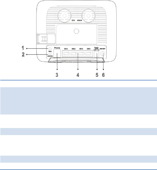
2.1 Rear Panel
1. Reset
Reset the Router by pressing this button.
2. Wi-Fi/WPS
Connect to other WPS-compatible devices by
pressing this button.
Wi-Fi function is turned on/off by a long press
(for 5 seconds).
WPS association window is activated by a short
press (less than 3 seconds).
3. Phone
Connect to the telephone line.
4. Ethernet
ports 1–4
Connect to your devices such as a PC and laptop.
Note: Eth1 also functions as a WAN port for
connecting to a DSL or cable modem.
5. 12 V
Connect to the power adapter
6. ON/OFF
Press to turn the power on or off.
9
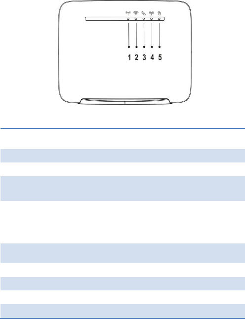
2.2 LED Definitions
1. 4G/3G/2G
Network
Cyan
Connected to 4G network
Blue
Connected to 3G network
Green
Connected to 2G network
Blinking
red (2 Hz)
Connection failure
Red
Failure during POST
(power-on self-test), or
error due to hardware or
firmware problems
2. Signal
Strength
Blue
Good coverage
Green
Minimum coverage
Red (2 Hz)
Poor coverage
3. Telephone
Blue
Off-hook
Off
On-hook

10
4. Wi-Fi/WPS
Blue
Wi-Fi interface on
Blinking
blue (2 Hz)
WPS setup process
Off
Wi-Fi interface off
5. Internet
Blue
Internet connection in
progress
Off
No internet connection
11
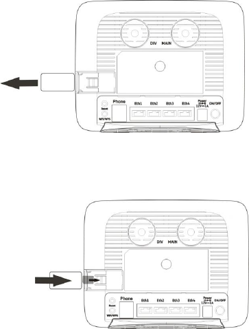
3. Installation
1. Open the SIM card slot cover.
2. Insert a SIM card into the SIM card slot, and slide the cover
back over the SIM card slot.
12
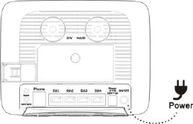
3. Connect the Router to the power adapter and plug the
power adapter into a wall outlet.
Note: Always use the adapter that comes with the Router
for the power supply.
4. Turn on the power switch of the Router.
13
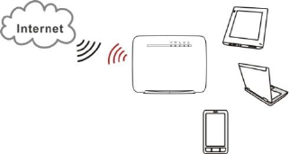
4. Connect devices to the Router
You can wirelessly connect devices to the Router or use RJ-45
Ethernet cables to connect via its LAN ports.
Note:
The DHCP server
in the Router is
turned on as a
default setting.
When connecting
a computer to
the Router,
please ensure that the computer is set up to obtain an IP
address automatically.
To connect devices to the Router wirelessly:
1. Enable the Wi-Fi function of devices such as your laptop,
tablet PC, or smartphone.
14
2. If your device supports WPS, press the WPS button on the
Router and then press the WPS button on your device to
establish a connection. If not, skip this step and complete
the steps below.
3. When the device finishes searching for Wi-Fi networks,
select the SSID of the Router.
Note: Each Router is configured with a default SSID and its
own unique password. Look for the label showing the SSID
and password information on the housing of the Router.
4. Enter the password from the label to associate your device
with the Router and connect to the Internet.
15
5. Web User Interface
5.1 Accessing the Web User Interface
The Web User Interface allows you to configure the Router
using your web browser.
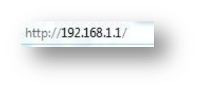
1. Ensure that the computer you use is connected to the
Router.
2. Open your web browser and type
192.168.1.1
in the address field.
3. An authentication screen will appear. Use the default
username and password printed on the label on the
housing of the Router.
4. The Web UI page will appear. Click the items on the
banner to access different management functions.
5. We recommend you change the password for greater
system security. Please access the Web UI and then go to
System Modify Password.
16
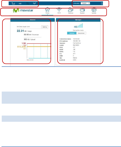
5.2 Web User Interface Introduction
1. Basic
Information
Provides information including:
Signal strength of the connected
mobile network, connection mode,
number of connected devices, and
unread SMS.
2. Language/Web
UI Log-out
Click the drop-down list to select a
preferred language.
3. Management
Function
Click the icon to access each
management function.
4. Internet Usage
Display of data usage
5. Connection
Information
Provides information including:
Name of the mobile network
service provider, connection mode,
cell ID, and LTE signal strength
indicators
1
2
3
4
5
17
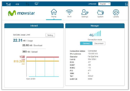
6. Home
This page displays basic system information including a
summary of the Internet, system, Wi-Fi, and Local Area
Network (LAN).
Internet:
Indicates Internet data usage, including total data usage
(download/upload); click Setting to view the data plan.
Manager:
Displays the connection mode, signal strength, and connection
information
18
7. Wi-Fi
Click the Wi-Fi icon on the top menu, and the following content
will appear. The side menu indicates the current displayed
menu.
Select the Wi-Fi profile for which you wish to change security
settings.
Note:
The Wi-Fi profile supports establishment of four local
wireless networks with different SSIDs. Each profile has its
own security mode.
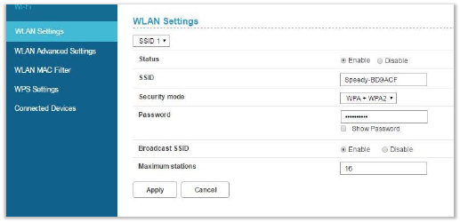
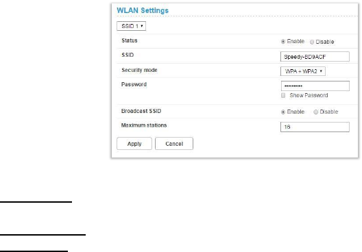
7.1 WLAN Settings
Status: Choose to Enable or Disable the SSID function.
19
SSID: The Service Set Identifier (SSID) is the name of the
wireless network broadcasting from this system. In order for
computers to connect to the local network over a wireless link,
they must select
this network
name from the
list of detected
wireless netw
orks in the area.
Security mode:
Select one
security method
from the
drop-down
menu.
None (Open): This mode allows all Wi-Fi devices to connect to
the Router without any security protection.
WPA2 Personal: Use for WPA2-level encryption.
WPA+WPA2: Enables both WPA- and WPA2-level wireless
protected access modes.
Password: Specify a password for your wireless network.
Show password: Displays the password when the check box is
selected.
Broadcast SSID: Select Enable if you want to broadcast this
SSID. The SSID will be displayed when you search for available
networks. Select Disable if you do not want to broadcast this
SSID.
Maximum stations: The maximum number of guest Wi-Fi
clients allowed on the Router.
20
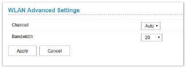
7.2 WLAN Advanced Settings
Channel: This specifies the frequency the radio uses to
transmit the wireless frames. Select a channel from the list of
channels or choose Auto to allow the system to determine the
best channel to use.
Bandwidth: You can then specify the bandwidth for each
channel. Click Apply to activate your settings.
7.3 WLAN MAC Filter
For detailed instructions on the WLAN MAC Filter, please refer
to section 8.4.
21
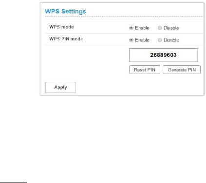
7.4 WPS Settings
WPS (Wi-Fi Protected Setup) is a computing standard for easy
and secure setup of a wireless connection. This function allows
rapid wireless connection between the Router and other
WPS-compatible devices.
<WPS Settings>
WPS mode:
Select Enable or Disable to enable or turn off the WPS
function.
WPS PIN mode:
Enable: Select Enable to connect using the PIN method:
1. Click Generate PIN to generate a PIN. Then enter the PIN
for another WPS-compatible device. Click Reset PIN to
reset the PIN.
2. Click Apply to apply the changes.
22
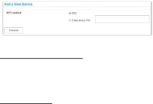
<Add a New Device>
WPS method:
PBC (Push-button configuration)
1. Select PBC.
2. Press the WPS button on the WPS-compatible device
that supports WPS connectivity.
3. Click Connect to establish a wireless connection.
Enter the device PIN
1. Enter the 8-digit numeric PIN of the WPS-compatible
device.
2. Click Connect to establish a wireless connection.
23
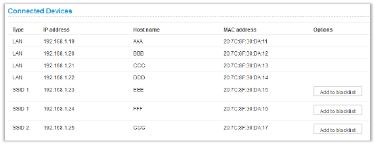
7.5 Connected Devices
The Connected Devices function presents a list of devices that
are currently connected to the Router, as well as the devices’
respective connection types.
When a wireless device is connected via Wi-Fi, you can click
the Add to blacklist button to add this device to the access
control list of MAC addresses. Connection to this device will
then be blocked.
24
8. Settings
Click the Settings icon on the top menu, and the following
content will appear. The side menu indicates the current menu
link.
25
8.1 Quick Setup
Click Quick Setup on the side menu to start configuring the
basic settings for using the Router. Detailed instructions can be
referenced in other sections of the manual.
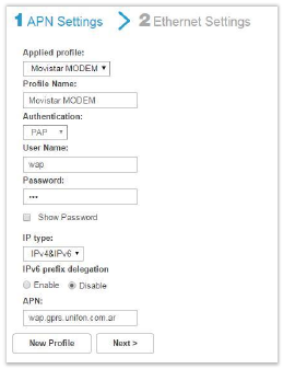
1 APN Settings > 2 Ethernet Settings
For detailed instructions on the APN Settings, please refer to
section 8.2.
26
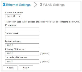
2 Ethernet Settings > 3 WLAN Settings
Select a connection mode and enter its related information to
complete the settings. Refer to section 8.3 for detailed
descriptions.
27
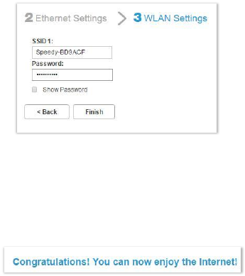
2 Ethernet Settings > 3 WLAN Settings
Specify a name and password for your wireless network, then
click Finish.
The statements below indicate that all the necessary settings
have been performed:
28
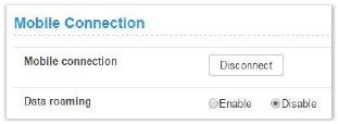
8.2 Dial-up
<Mobile Connection>
Mobile connection: Your mobile connection status is displayed
here. Click Disconnect to disable mobile data connection.
Data roaming: Click Enable to activate the data roaming
function. Click Disable to stop data roaming.
29
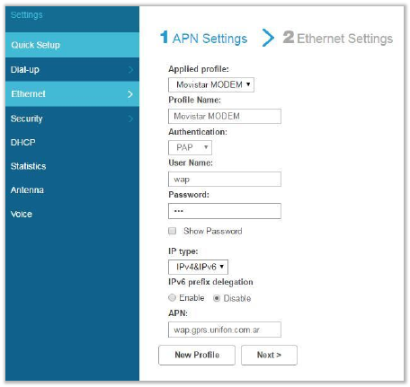
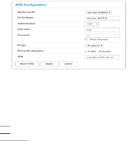
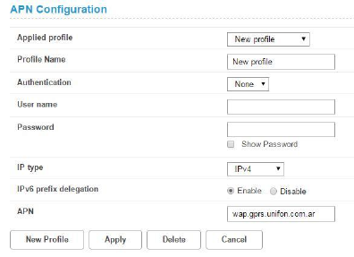
<APN Configuration>
Applied profile: Select a profile from the drop-down list.
Profile Name: Specify a profile name for the selected profile.
Authentication: Select an authentication type for the profile.
User name: The user name that you registered for the service.
Password: The password that you registered for the service.
IP type:
IPv4: Use Internet Protocol version 4 (IPv4).
IPv6: Use Internet Protocol version 6 (IPv6).
IPv4 & IPv6: Use both IPv4 and IPv6.
IPv6 prefix delegation: Click Enable to enable prefix delegation.
Click Disable to stop the prefix delegation function.
APN: Specify the Access Point Name (APN).
After the settings are completed, click Apply.
To create a new profile, click New Profile. The following
window will then appear:
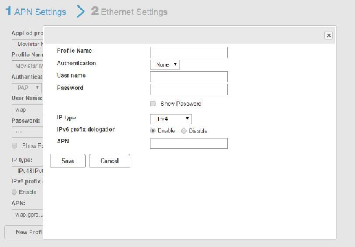
30
After you enter the related information, click Save.
If you want to delete a particular profile, select the profile you
want to delete and then click Delete.
31
32
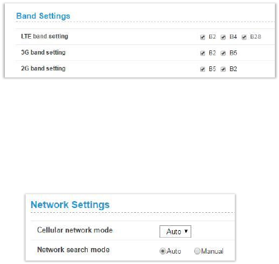
<Band Settings>
The section enables you to perform settings for the LTE band,
3G band, and 2G band. Select the appropriate check boxes and
click Apply to apply the changes.
<Network Settings>
Cellular network mode: Select your operator’s network mode
to log in to the network.
Network search mode: Select Auto or Manual to search the
network.
33
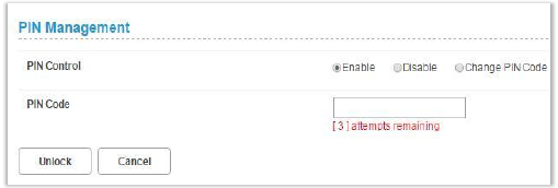
<PIN Management>
PIN Control: Select Enable to enable PIN protection.
Select Disable to disable PIN protection.
Change PIN Code: Select this function to change your PIN.
Please note that PIN can only be set when PIN control is
enabled.
34
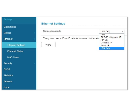
8.3 Ethernet
Ethernet Settings
You can select a connection mode for your Internet connection
according to your application situation.
<Auto>
In Auto mode, the Router selects the best network access
mode based on the network environment.
1. Select Auto from the Connection mode drop-down list.
2. Set Point-to-Point Protocol over Ethernet (PPPoE) and the
Dynamic IP parameters.
35
< PPPoE + Dynamic IP >
The PPPoE + Dynamic IP mode enables you to access the
Internet using a PPPoE dial-up connection or a dynamic IP
address.
1. Select PPPoE + Dynamic IP from the Connection mode
drop-down list.
2. Set Point-to-Point Protocol over Ethernet (PPPoE) and
Dynamic IP parameters.
< PPPoE>
This option is normally used by the DSL modem users to enter
authentication information. You will need to have the user
name and password provided by your network service provider
for the PPPoE dial-up connection.
1. Select PPPoE from the Connection mode drop-down list.
2. Enter the user name and password provided by your
network service provider.
3. Set the MTU. The default MTU size is 1480. Please do not
edit the number unless absolutely necessary.
<Dynamic IP>
This option is suitable for Internet services that do not require
account authentication, for example, in most cable-modem
usage scenarios.
1. Select Dynamic IP from the Connection mode drop-down
list.
2. Select the Set DNS server manually check box.
36
3. Enter Primary DNS server and Secondary DNS server.
4. Set the MTU. The default MTU size is 1480. Please do not
edit the number unless absolutely necessary.
<Static IP>
This option is suitable for services that use a fixed IP address.
1. Select Static IP from the Connection mode drop-down list.
2. Enter the IP address, subnet mask, gateway address, and
DNS address (optional) provided by your network service
provider.
3. Set the MTU. The default MTU size is 1480. Please do not
edit the number unless absolutely necessary.
<LAN Only>
This option is suitable when the client is connected with a
network cable but without Ethernet connection.
1. Select LAN only from the Connection mode drop-down
list.
37
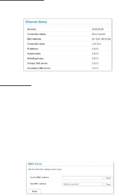
Ethernet Status
The section displays basic Ethernet status. To change the
connection status, go to Settings Ethernet Settings.
MAC Clone
Some ISPs may register the MAC address of your computer
when dialing up to the Internet for the first time via modem. If
you add a router into your network to share your Internet
connection, the ISP will not accept that policy. Therefore, you
need to create a MAC clone on the router.
At the Host MAC address field, click Clone to clone your PC’s
MAC address as the WAN MAC address of the router. The same
MAC address will be cloned to the Current MAC address field.
Click Apply to save the settings.
38
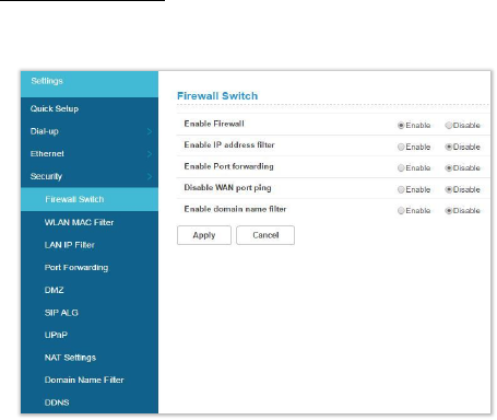
8.4 Security
Firewall Switch
A firewall is used to prevent traffic from entering and/or
leaving the areas of your network.
Enable Firewall: The Router has a built-in firewall. To disable
the firewall, select Disable.
Enable IP address filter: To limit the Internet access on some
specified computers through the router, enable the IP Address
Filter.
Enable Port forwarding: Port Forwarding can be used to
translate the common service port to a custom port inside your
local network such as web or FTP.
Disable WAN port ping: Disabling WAN port ping will make the
Router drop any ICMP ping requests (which is usually used for
39
network diagnostic purposes) to prevent DoS (Denial of Service)
attacks.
Enable domain name filter: Domain name filter can be used to
block computers from accessing certain websites through the
router.
Click Apply to activate your settings.
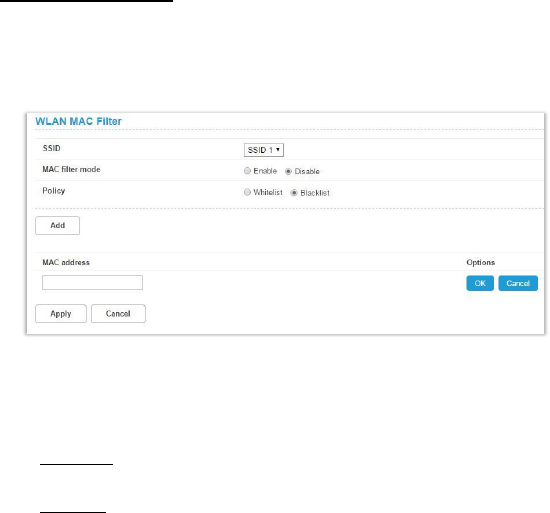
WLAN MAC Filter
Enabling the WLAN MAC Filter function allows you to block or
allow computer devices from establishing a wireless link to the
Router. The filtering is based on the wireless computer’s
unique hardware ID (MAC address).
1. Select an SSID and choose a corresponding MAC filter
mode (Enable or Disable).
2. Select a policy for the MAC filter mode:
Whitelist: Only devices with its MAC address listed here
are allowed to connect to this Router via Wi-Fi.
Blacklist: Devices with its MAC address listed in the table
40
will be blocked when attempting to connect to this Router
via Wi-Fi.
To add a MAC address to the Blacklist or Whitelist, click Add
and enter the MAC address. Then click OK and Apply.
41
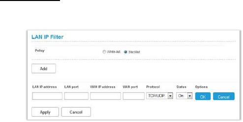
LAN IP Filter
Turn the LAN IP Filter on to limit the Internet access on some
specified computers.
1. In the Policy field, select Whitelist or Blacklist if you would
like to allow or ban connections, respectively, of a certain
device.
2. Click Add and type the IP address of the device in the
LAN IP address field.
3. Type the value range of the LAN port in the LAN port field.
4. Type the value range of the WAN port in the WAN port
field.
5. At the Protocol drop-down list, select a protocol. The
service uses the following layer-4 protocols: TCP, UDP, and
ICMP.
6. At the Status drop-down list, select On or Off as the status
of the service.
7. At Options, click OK to complete entry of the information.
Click Cancel to undo the changes.
8. Click Apply to confirm your settings.
42
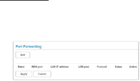
Port Forwarding
Port Forwarding can be used to open certain ports of a device
to communicate with an Internet service. If a computer in your
LAN is configured as a Web server, a designated port must also
be opened for devices from the Internet to communicate with
this server.
Name: The name of the service for which the port forwarding
rule has been created
WAN port: Type the value range of the WAN port.
LAN IP address: The IP address of the computer on the local
network to which the traffic will be forwarded
LAN port: Type the value range of the LAN port.
Protocol: The layer-4 protocol that the service uses. This can
be TCP, UDP, or both. If you are unsure, select the TCP/UPD
option.
Status: Select On or Off as the status of the service.
1. To add a port mapping rule, click Add.
2. Enter the relevant information for which the port
forwarding rule has been created.
3. Select the protocol it uses from the Protocol drop-down
list, then select On or Off.
4. Click Apply to save your changes.
43
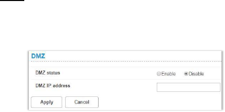
DMZ
DMZ (De-Militarized Zone) allows you to specify a DMZ host IP
to redirect requests to a virtual DMZ host in order to enhance
the security of the local area network.
DMZ status: If this function is enabled, threats from external
networks will be directed to the DMZ instead of the network.
DMZ IP address: The IP address of the host DMZ.
To designate a device as a DMZ host, enter its IP address in the
DMZ IP Address text field. Click Apply to apply the changes, or
click Cancel to undo your configuration.
44
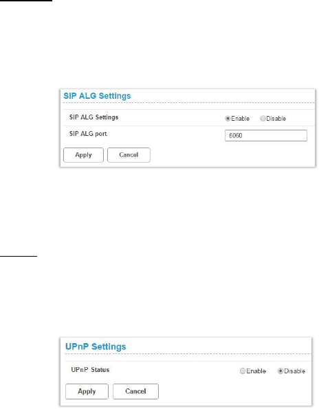
SIP ALG
The Session Initiation Protocol (SIP) is used to begin, change, or
end a session, and an Application Layer Gateway (ALG) is
a security component for checking the status of data packages.
To complete an SIP ALG, enable the SIP ALG Settings function.
1. Select Enable to enable the SIP ALG.
2. In SIP ALG port, specify the SIP port number provided by
your Internet service provider. Click Apply.
UPnP
For devices that support Universal Plug and Play (UPnP),
enabling the UPnP function will allow automatic port
forwarding that helps your UPnP devices communicate with
the Internet.
1. At the UPnP Status, select Enable to enable the UPnP port
mapping function.
2. Click Apply to apply the settings.
45
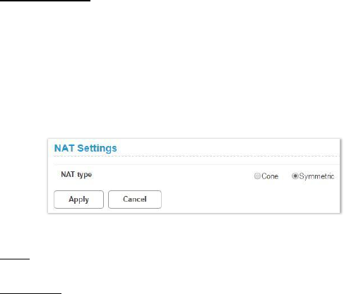
NAT Settings
Network Address Translation (NAT) is a technique which allows
several computers on a LAN to share an Internet connection.
The computers on the LAN use a “private” IP address range
while the WAN port is configured with a single “public”
IP address.
Along with connection sharing, NAT also hides internal
IP addresses from computers on the Internet.
NAT Type:
Cone: Based on a cone NAT type, the port is permanently open
and allows inbound connections from any external host.
Symmetric: Each request from the same internal IP address
and port to a specific destination IP address and port is
mapped to a unique external source IP address and port. Even
if the same internal host sends a packet with the same source
address and port but to a different destination, a different
mapping is used. Only an external host that receives a packet
from an internal host can send a packet back.
Select an NAT type, and then click Apply. Click Cancel to undo
the settings.
46
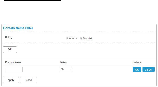
Domain Name Filter
A domain name filter can be used to block computers from
accessing certain websites through the router.
1. At the Policy field, select Whitelist or Blacklist to allow or
block a domain name.
2. Click Add to create an entry, and type in the domain name
in the Domain Name text field.
3. Select On or Off from the Status drop-down list.
4. At Options, click OK to complete entry of the information.
Click Cancel to undo the changes.
5. Click Apply to activate your settings.
47
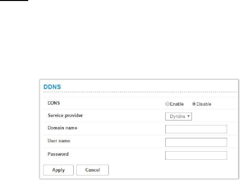
DDNS
Dynamic DNS (DDNS) is an Internet service that allows routers
with varying public IP addresses to be located using Internet
domain names. To use DDNS, you must set up an account with
a DDNS provider such as DynDNS.org and fill in the required
account details including the Domain Name, Username, and
Password on this page.
Service provider: Select the DNS service that you are
subscribed to.
Domain name: Enter the domain name of the DDNS account.
User name: Enter the username of the DDNS account. This will
be provided by the DDNS service provider.
Password: Enter the password for the DDNS account.
Click Apply to apply the changes, or click Cancel to undo your
configurations.
48
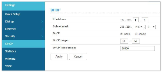
8.5 DHCP
DHCP assigns LAN IP addresses for connected devices. You can
specify an IP address range for the Router to assign from.
IP address: Specify an IP address range for the Router to assign
from.
Subnet mask: The subnet mask along with the previously
configured IP address defines the network. The default value
for subnet mask is 255.255.255.0.
DHCP: Select Enable or Disable to activate the function.
DHCP range: Type a DHCP range in the fields.
DHCP lease time(s): You can specify a period of time after
which an assigned IP address will be retrieved from devices
due to the fact that there has been no network activity during
the time specified.
Click Apply to apply the settings.
49
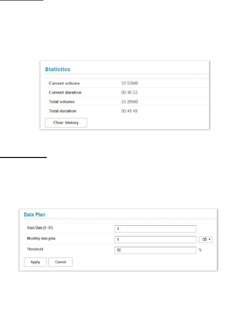
8.6 Statistics
Statistics
Here you can view the statistics of the router, including total
traffic volume/duration and current traffic volume/duration of
the last packets statistic interval.
To reset the statistics, click Clear history.
Data Plan
You can set the monthly traffic statistics and view the network
traffic of the month. Set the monthly traffic statistics
parameters and click Apply to apply the settings.
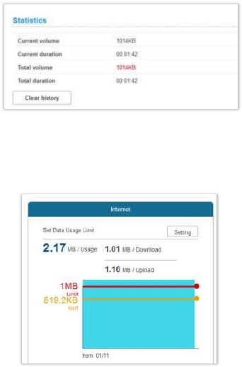
Note: When your data usage exceeds the defined threshold,
the total volume will be highlighted in red text.
50
Meanwhile, the blue area that indicates current data usage will
exceed the defined threshold indicated by a red line.
51
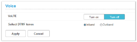
8.7 Voice
VoLTE: Select Turn on to activate VoLTE on the router. Select
Turn off to use CSFB (Circuit-Switched Fallback).
DTMF (Dual Tone Multi-Frequency) tones are used during a call
to signal to a far-end device; these signals may be for
navigating a menu system, entering data, or for other types of
manipulation. For the Select DTMF tones, select Inband or
Outband. It is recommended that you do not change the
default settings.
52
9. System
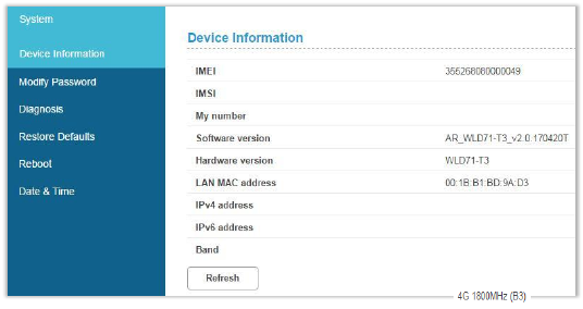
9.1 Device Information
This page displays relevant information of the Router including:
IMEI, IMSI, your number, software version, hardware version,
LAN MAC address, IPv4 address, and IPv6 address.
53
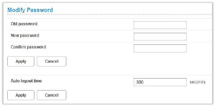
9.2 Modify Password
You can change the password used for accessing this Web UI
and adjust the session expiration time.
To modify your password, type the old password first. Then
input a new password and re-type the password in the Confirm
password field. Click Apply to apply the settings.
To adjust the login time-out on the Web UI, input a time range
between 30 seconds–600 seconds at the Auto logout time field.
Click Apply to set your preferences.
54
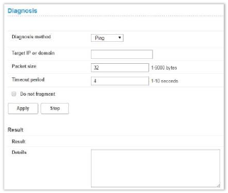
9.3 Diagnosis
If the Router cannot connect to the Internet, you can perform a
diagnosis to find out the possible causes.
<Ping>
Select Ping from the Diagnosis method drop-down list.
1. Enter the IP address or domain name in the Target IP or
domain text field.
2. Set the Packet size.
3. Set the Timeout period.
4. Select or clear Do not fragment.
5. Clear Do not fragment if you set Packet size to a value
greater than its default value.
6. Click Apply. The diagnostics results will then be displayed
in the Result area at the bottom of the page.
55
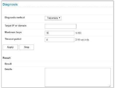
<Traceroute>
Select Traceroute from the Diagnosis method drop-down list.
1. Enter the IP address or domain name in the Target IP or
domain text field.
2. Set the Maximum hops.
3. Set the Timeout period.
4. Click Apply. The diagnostics results will then be displayed
in the Result area at the bottom of the page.
9.4 Restore Defaults
To reset all the Router’s settings to the factory default, click
Restore.
56
9.5 Reboot
To restart the device, click Reboot.
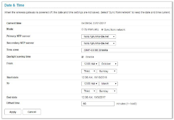
9.6 Date and Time
Network Time Protocol (NTP) is a protocol that is used to
synchronize the computer clock time among a network of
computers. This page allows you to set the date, time, and NTP
(Network Time Protocol) servers. Accurate time across a
network is important for logging and execution of scheduled
57
upgrades and scheduled policies. Setting the system time
correctly is also required to enable the firewall schedules to
function properly.
Current time: Displays the current time of the Router.
Mode: You can set the computer clock time manually or
choose to synchronize the time automatically.
Primary NTP server: Select an NTP server from the drop-down
list to sync.
Secondary NTP server: The second NTP server to sync in case
the first server does not respond. Select one from the
drop-down list.
Time zone: Select the local time zone.
Daylight saving time: Check Enable to turn on the daylight
saving function.
From: Specify the start time to apply daylight savings time.
Start date: Enter the start date on which you wish the
synchronization to start.
To: Specify the end date in which you wish the synchronization
to end.
End date: Enter the end date on which you wish the
synchronization to end.
Offset time: Specify a value between 1–1440 (minutes) as the
offset time.
If you want to configure the time manually, select Manual and
enter the local time.

58
9.7 SMS
In this section, you can write new messages and view messages
saved in your Inbox, Outbox, and Drafts. You may also view the
SMSs stored on your SIM.
1. New Message
You can compose new messages
in this section.
2. Inbox
The section displays relevant
information related to the
messages stored in your Inbox.
3. Outbox
The section displays relevant
information related to the
messages that have been
delivered.
4. Drafts
The section lists the uncompleted
messages temporarily saved.
5. SIM SMS
The section displays relevant
information of SMSs stored on
your SIM.
6. SMS Settings
The section enables you to select
SMS over IMS or SMS over SGs.
59
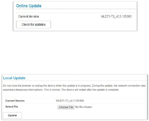
10. Update
10.1 Online Update
Firmware will be continually updated as more features are
added and known issues are resolved.
This section shows the current version of your firmware and
helps you upgrade the firmware to the latest version online.
Click Check for updates to see if updates are available.
10.2 Local Update
This section allows you to select a file locally to perform an
update. At the Select File field, click Choose File and select the
update package saved on your computer.
60
11. Specifications
Hardware and Port Characteristics
Button: Power/Reset/WPS
SIM Card Slot: 3FF (Micro)
Power Adapter: DC 12 V/1 A
Ethernet Port: 4 × Fast Ethernet LAN
RJ11 Port (6P2C) × 1
LGA Modules (Cat. 4)
LTE: 2/4/28, 3G: 2/5 GSM: 2/5
@ supported 20 MHz bandwidth
LTE Antenna
Internal antennas × 2
WLAN
IEEE 802.11b/g/n–compliant
Antenna:
Two internal antennas for Wi-Fi 2.4 G
Environmental
Ambient Operating Temperature: –10 °C to +50 °C
Ambient Operating Humidity: 5% to 95%
Storage Temperature: –25 °C to +70 °C
Dimensions
168 mm × 131.2 mm × 59.1 mm