Wistron NeWeb XRAGP3 Second Generation RFID Smart Reader User Manual

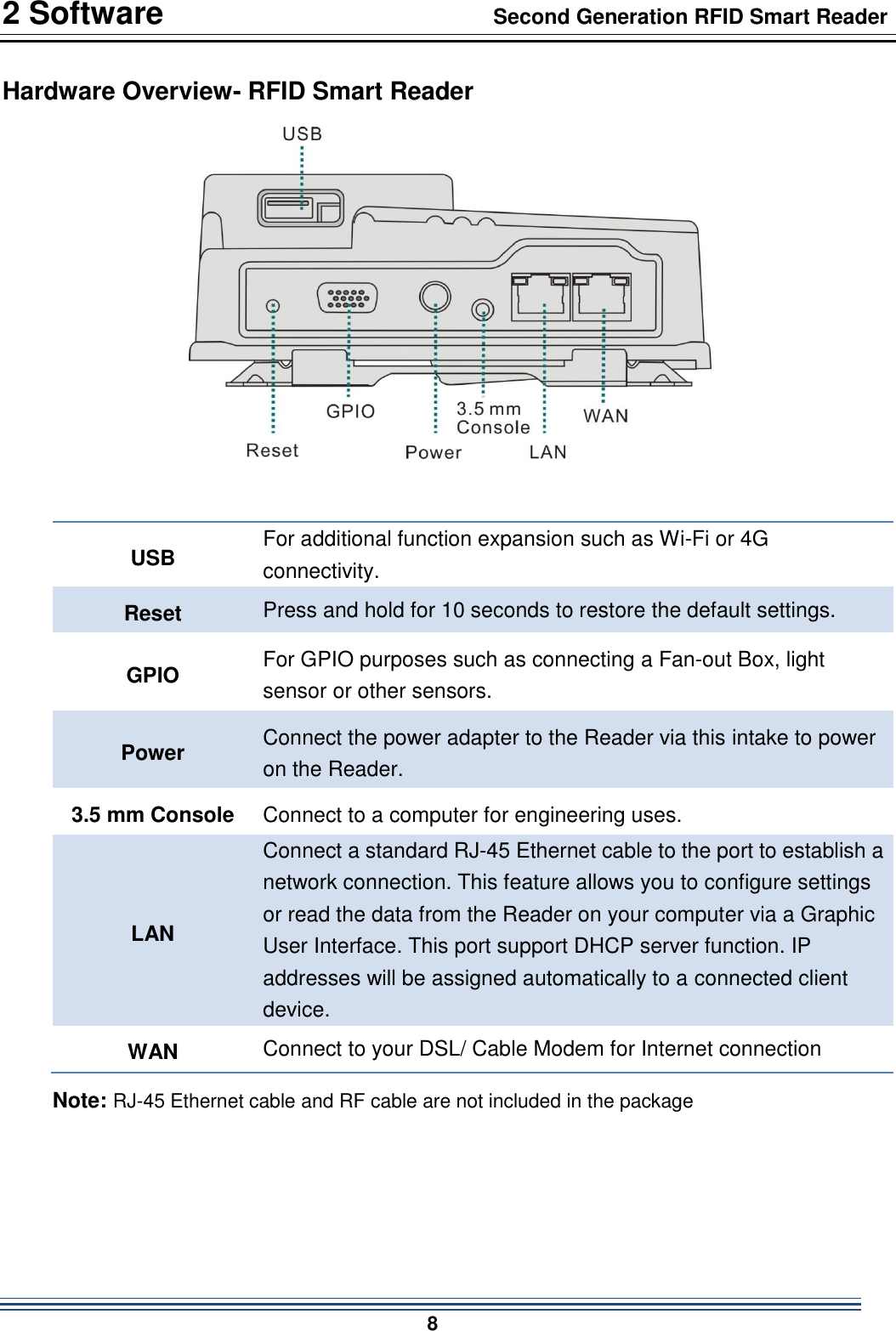
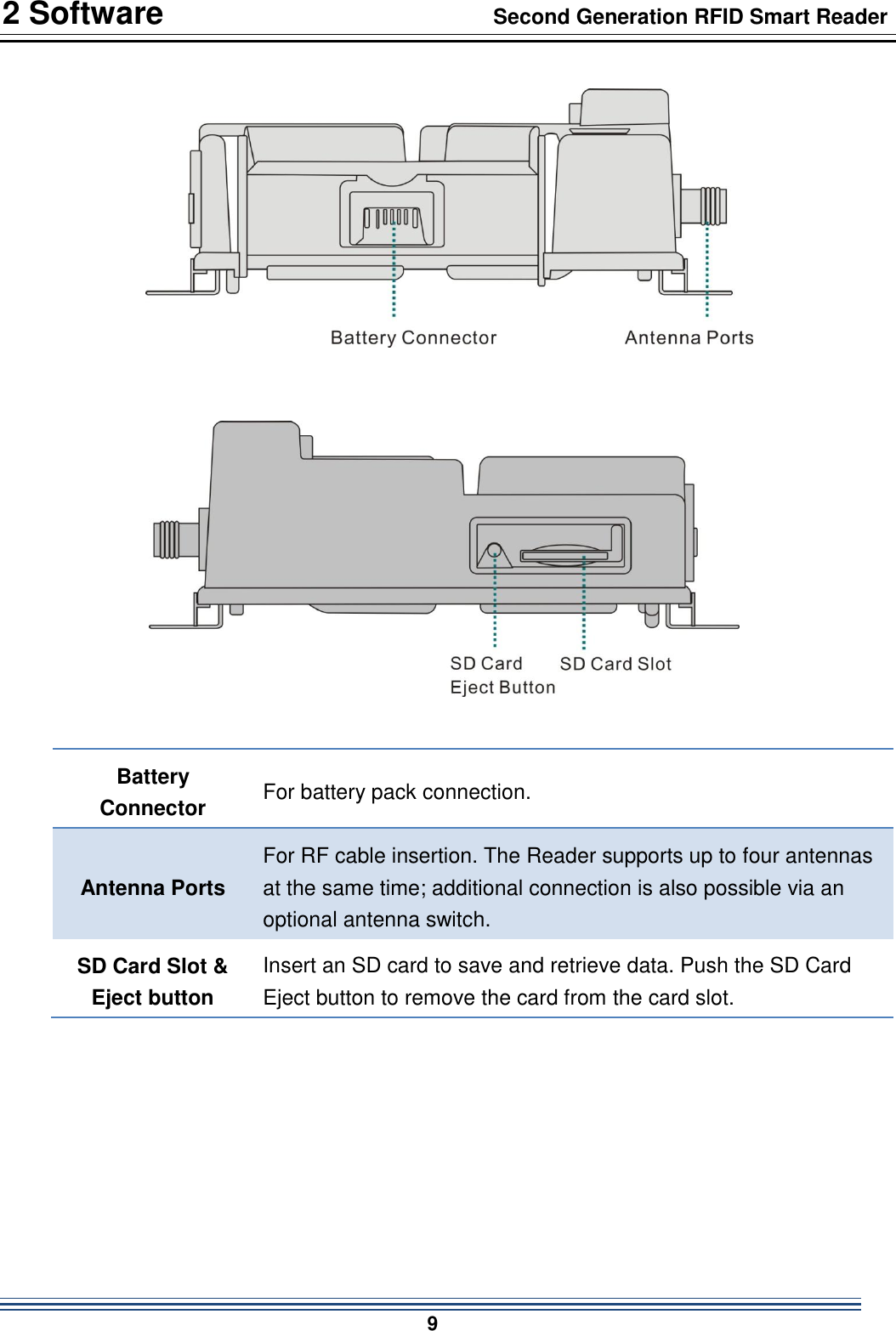
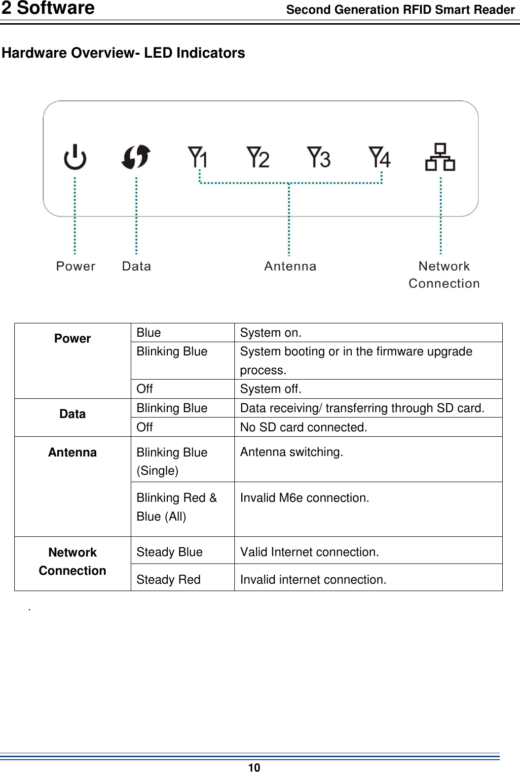
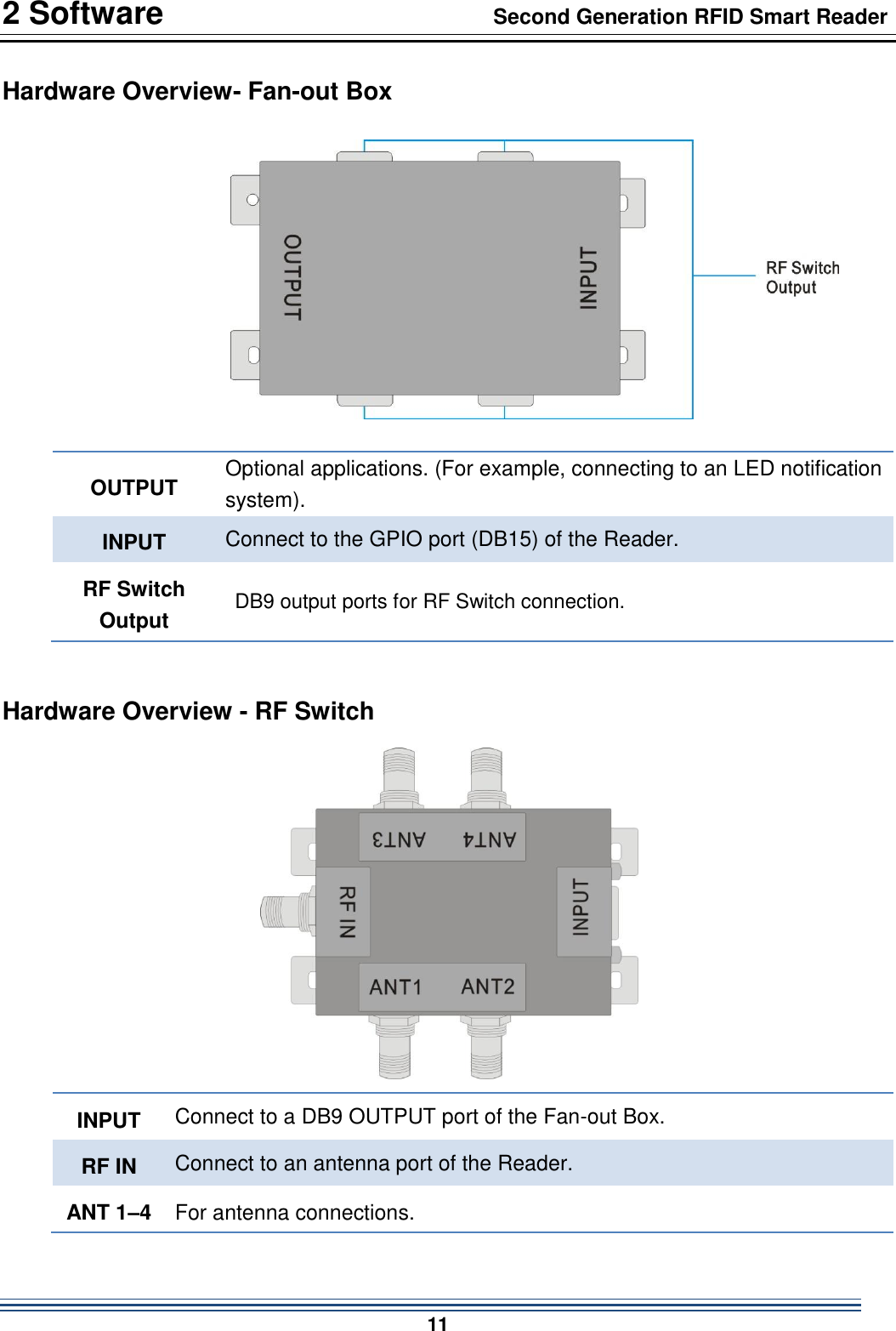
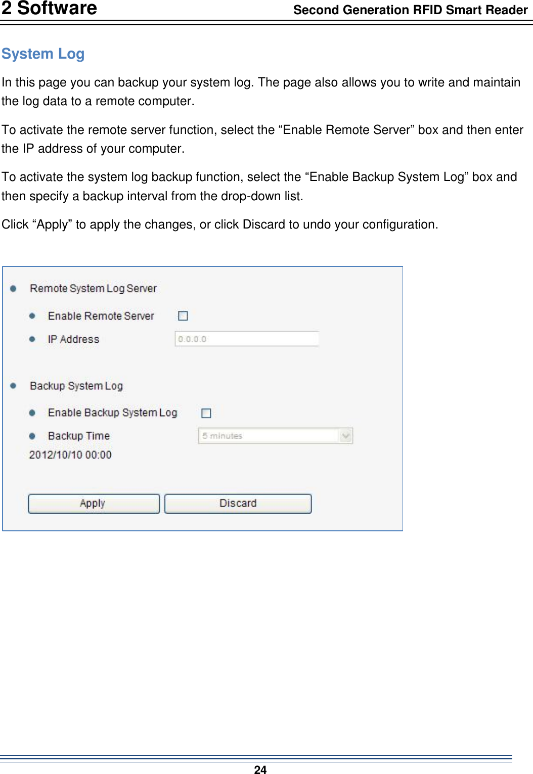
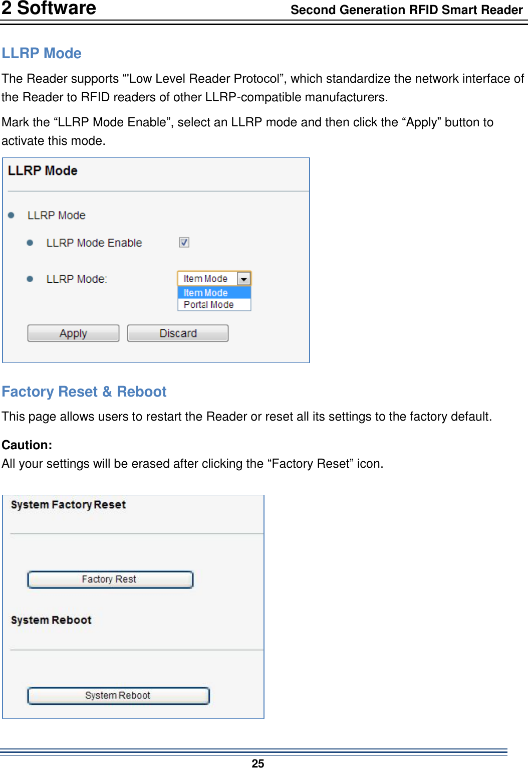
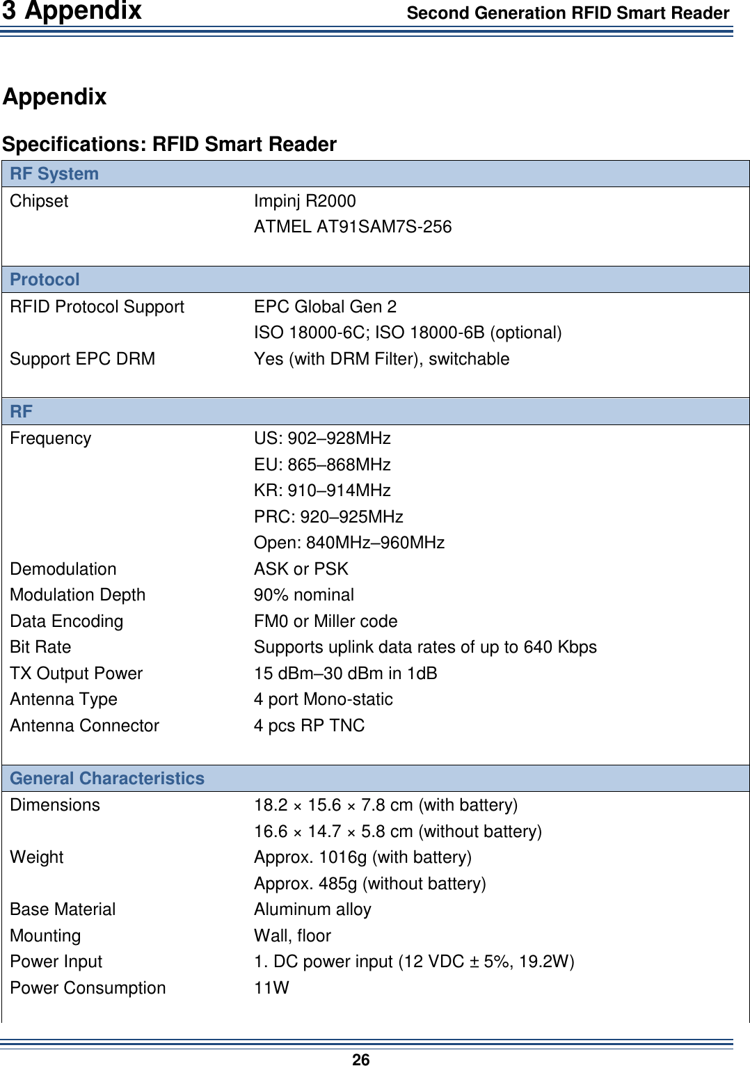
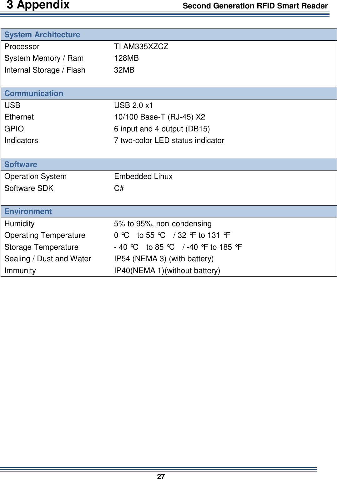
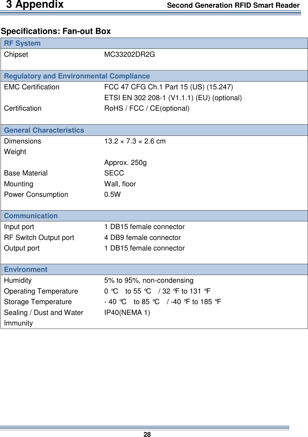
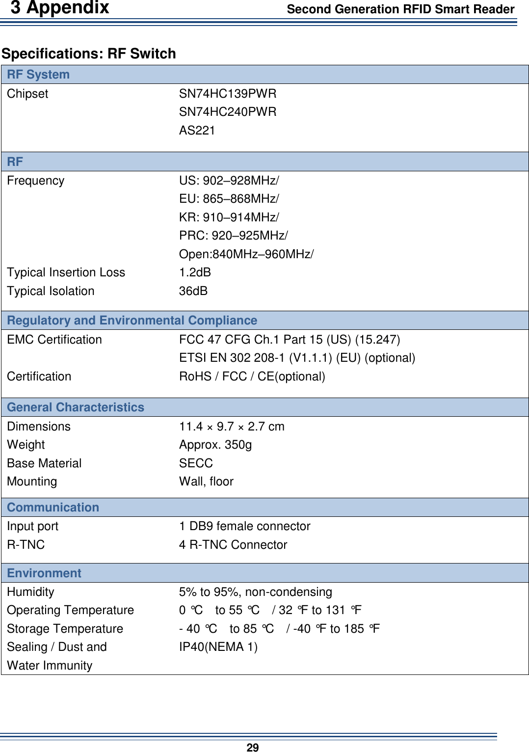
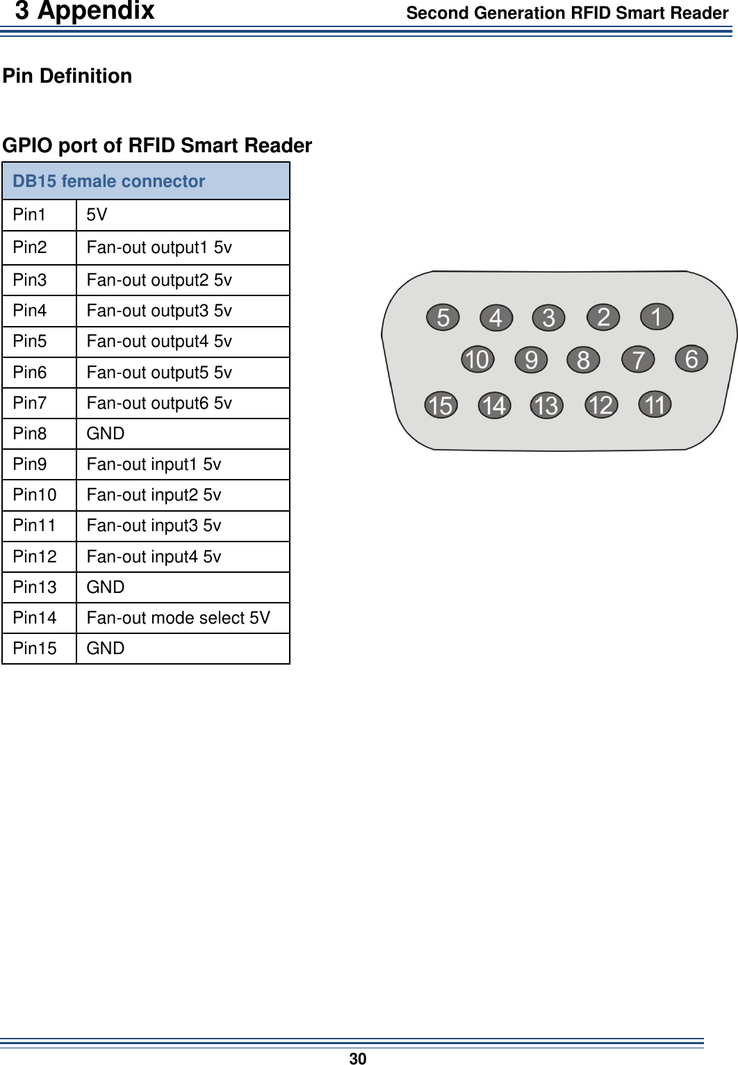
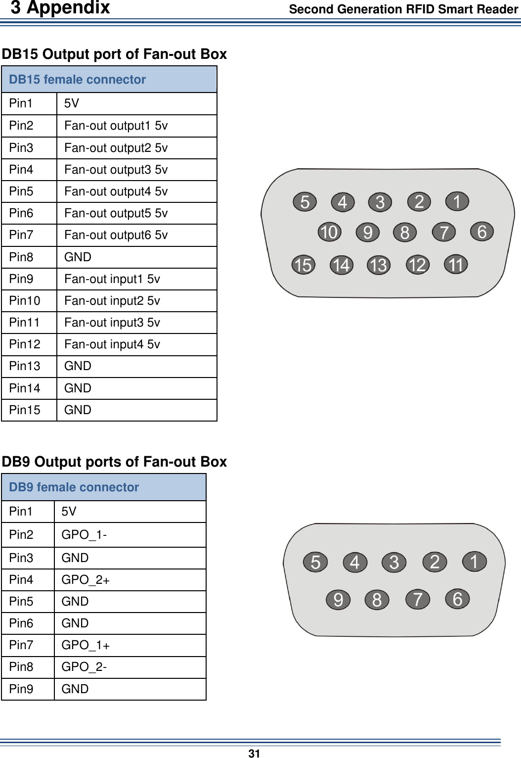
Wistron NeWeb Corporation Second Generation RFID Smart Reader

User Manual.pdf

                Second Generation RFID Smart Reader with Fan-out Box and RF Switch User Manual English
Table of Contents                 Second Generation RFID Smart Reader                        1  1. REGULATORY INFORMATION ................................................................... 2 2. GETTING STARTED .................................................................................... 5 IN THE PACKAGE ................................................................................................. 5 INTRODUCTION ................................................................................................... 6 HARDWARE OVERVIEW- RFID SMART READER ...................................................... 8 HARDWARE OVERVIEW- LED INDICATORS ........................................................... 10 HARDWARE OVERVIEW- FAN-OUT BOX ............................................................... 11 HARDWARE OVERVIEW - RF SWITCH .................................................................. 11 CONNECTING THE CABLES ................................................................................. 12 3. CONFIGURATION SOFTWARE ................................................................. 15 ACCESS THE MANAGEMENT INTERFACE (WEB UI) ................................................ 15 MANAGEMENT: HOME ........................................................................................ 16 MANAGEMENT: ETHERNET ................................................................................. 17 LAN Settings .............................................................................................................................. 17 WAN Settings ............................................................................................................................ 18 MANAGEMENT: WIRELESS ................................................................................. 19 Wi-Fi Offload ............................................................................................................................. 19 4G Settings ................................................................................................................................ 20 MANAGEMENT: SYSTEM .................................................................................... 21 Firmware Upgrade .................................................................................................................... 21 User Account ............................................................................................................................ 22 Time Settings ............................................................................................................................ 23 System Log ................................................................................................................................ 24 LLRP Mode ................................................................................................................................ 25 Factory Reset & Reboot ............................................................................................................ 25 4. APPENDIX .................................................................................................. 26 SPECIFICATIONS: RFID SMART READER ............................................................. 26 SPECIFICATIONS: FAN-OUT BOX ......................................................................... 28 SPECIFICATIONS: RF SWITCH ............................................................................ 29 PIN DEFINITION ................................................................................................. 30
2 Software                                Second Generation RFID Smart Reader                           2  Regulatory Information Federal Communication Commission Interference Statement This device complies with Part 15 of the FCC Rules. Operation is subject to the following two conditions: (1) This device may not cause harmful interference, and (2) this device must accept any interference received, including interference that may cause undesired operation. This equipment has been tested and found to comply with the limits for a Class B digital device, pursuant  to  Part  15  of  the  FCC  Rules.    These  limits  are  designed  to  provide  reasonable protection against harmful interference in a residential installation. This equipment generates, uses and can radiate radio frequency energy and, if not installed and used in accordance with the instructions, may cause harmful interference to radio communications.    However, there is no guarantee that interference will not occur in a particular installation.    If this equipment does cause harmful interference to radio or television reception, which can be determined by turning the equipment off and on, the user is encouraged to try to correct the interference by one of the following measures:    Reorient or relocate the receiving antenna.   Increase the separation between the equipment and receiver.   Connect the equipment into an outlet on a circuit different from that to which the receiver is connected.   Consult the dealer or an experienced radio/TV technician for help.  FCC Caution: Any changes or modifications not expressly approved by the party responsible for compliance could void the user's authority to operate this equipment. This transmitter must not be co-located or operating in conjunction with any other antenna or transmitter.  Radiation Exposure Statement: This  equipment  complies  with  FCC  radiation  exposure  limits  set  forth  for  an  uncontrolled environment. This equipment should be installed and operated with minimum distance 20cm between the radiator & your body.
2 Software                                Second Generation RFID Smart Reader                           3  Industry Canada statement: This device complies with RSS-210 of the Industry Canada Rules. Operation is subject to the following two conditions: (1) This device may not cause harmful interference, and (2) this device must accept any interference received, including interference that may cause undesired operation. Ce dispositif est conforme à la norme CNR-210 d'Industrie Canada applicable aux appareils radio exempts de licence. Son fonctionnement est sujet aux deux conditions suivantes: (1) le dispositif ne doit pas produire de brouillage préjudiciable, et (2) ce dispositif doit accepter tout brouillage reçu, y compris un brouillage susceptible de provoquer un fonctionnement indésirable.   Radiation Exposure Statement: The product comply with the Canada portable RF exposure limit set forth for an uncontrolled environment and are safe for intended operation as described in this manual. The further RF exposure reduction can be achieved if the product can be kept as far as possible from the user body or set the device to lower output power if such function is available. Déclaration d'exposition aux radiations: Le  produit  est  conforme  aux  limites  d'exposition  pour  les  appareils  portables  RF  pour  les Etats-Unis et le Canada établies pour un environnement non contrôlé. Le produit est sûr pour un fonctionnement tel  que décrit dans ce manuel. La réduction aux expositions RF peut être augmentée si l'appareil peut être conservé aussi loin que possible du corps de l'utilisateur ou que le dispositif est réglé sur la puissance de sortie la plus faible si une telle fonction est disponible. Radiation Exposure Statement: This  equipment  complies  with  IC  radiation  exposure  limits  set  forth  for  an  uncontrolled environment. This equipment should be installed and operated with minimum distance 20cm between the radiator & your body. Déclaration d'exposition aux radiations: Cet équipement est conforme aux limites d'exposition aux rayonnements IC établies pour un environnement non contrôlé. Cet équipement doit être installé et utilisé avec un minimum de 20 cm de distance entre la source de rayonnement et votre corps.
2 Software                                Second Generation RFID Smart Reader                           4  警告聲明:   經型式認證合格之低功率射頻電機,非經許可,公司、商號或使用者均不得擅自變更頻率、加大功率或變更原設計之特性及功能。 低功率射頻電機之使用不得影響飛航安全及干擾合法通信;經發現有干擾現象時,應立即停用,並改善至無干擾時方得繼續使用。前項合法通信,指依電信法規定作業之無線電通信。低功率射頻電機須忍受合法通信或工業、科學及醫療用電波輻射性電機設備之干擾。
2 Software                                Second Generation RFID Smart Reader                           5  Getting Started In the Package     Second Generation   RFID Smart Reader Power Cord Power Adapter       Fan-out Box (optional) RF Switch (optional) Battery (optional)     Note:     The Fan-out Box and RF Switch work in combination to allow more antenna connections. One Second Generation RFID Smart Reader can connect to one Fan-out Box and four RF Switches.       The battery can be used to power the Reader for approximately 6 hours. It snaps onto the Smart Reader and forms a complete unit.
2 Software                                Second Generation RFID Smart Reader                           6  Introduction The Second Generation RFID Smart Reader (the Reader) enhances the flexibility of its former version by adding a portable feature and wireless connectivity. You can choose to add a battery to the Reader and work in combination with a dedicated antenna for portable use such as the NeWave Smart Vest. An expansion dongle slot is provided for connecting a Wi-Fi dongle or LTE dongle with which you can easily send the collected data wirelessly.   The Reader is designed for uses with a variety of UHF RFID applications. It provides high level RF performance, a user-friendly software development interface and a cost competitive reader solution. Combined with our Wave Antennas, it can provide 100% readability in area sizes of 2’ × 2’ × 2’ to 10’ × 10’ × 10’ when appropriate reader parameters and antennas are set up. You can also connect the Reader to a Fan-out Box and 1 to 4 RF Switches to add additional antennas. A maximum of 16 antennas are allowed with one Reader. For multi-reader applications, such as retail applications, the Reader solution can efficiently compress data size and solve data traffic issues.    Basic application:   You can connect to up to four antennas and use a computer to monitor detected parameters.
2 Software                                Second Generation RFID Smart Reader                           7  Advanced application:   Use the Reader with a Fan-out Box and an RF Switch to connect up to 16 antennas.
2 Software                                Second Generation RFID Smart Reader                           8  Hardware Overview- RFID Smart Reader    USB For additional function expansion such as Wi-Fi or 4G connectivity. Reset Press and hold for 10 seconds to restore the default settings. GPIO For GPIO purposes such as connecting a Fan-out Box, light sensor or other sensors.   Power Connect the power adapter to the Reader via this intake to power on the Reader. 3.5 mm Console Connect to a computer for engineering uses. LAN Connect a standard RJ-45 Ethernet cable to the port to establish a network connection. This feature allows you to configure settings or read the data from the Reader on your computer via a Graphic User Interface. This port support DHCP server function. IP addresses will be assigned automatically to a connected client device.   WAN Connect to your DSL/ Cable Modem for Internet connection Note: RJ-45 Ethernet cable and RF cable are not included in the package
2 Software                                Second Generation RFID Smart Reader                           9      Battery Connector For battery pack connection. Antenna Ports For RF cable insertion. The Reader supports up to four antennas at the same time; additional connection is also possible via an optional antenna switch. SD Card Slot & Eject button Insert an SD card to save and retrieve data. Push the SD Card Eject button to remove the card from the card slot.
2 Software                                Second Generation RFID Smart Reader                           10  Hardware Overview- LED Indicators    Power Blue System on. Blinking Blue System booting or in the firmware upgrade process. Off System off. Data Blinking Blue Data receiving/ transferring through SD card. Off No SD card connected. Antenna Blinking Blue (Single) Antenna switching. Blinking Red & Blue (All) Invalid M6e connection. Network Connection Steady Blue Valid Internet connection. Steady Red Invalid internet connection. .
2 Software                                Second Generation RFID Smart Reader                           11  Hardware Overview- Fan-out Box                                      OUTPUT Optional applications. (For example, connecting to an LED notification system).   INPUT Connect to the GPIO port (DB15) of the Reader. RF Switch   Output DB9 output ports for RF Switch connection.      Hardware Overview - RF Switch  INPUT Connect to a DB9 OUTPUT port of the Fan-out Box. RF IN Connect to an antenna port of the Reader.   ANT 1–4   For antenna connections.
2 Software                                Second Generation RFID Smart Reader                           12  Connecting the Cables Basic installation:      1. Plug an RF cable into an antenna port and an antenna. The Reader supports up to four antennas at the same time. 2. Connect an RJ-45 Ethernet cable to the LAN port and to your computer for software development interface configuration. 3. Connect the power adapter to the Power port on the Reader. Once the power adapter is connected to the Reader, the Power LED indicator will turn blue indicating the power is on. Note: The Reader may be wall-mounted. Insert screws into the four holes on the left and right side brackets of the Reader.
2 Software                                Second Generation RFID Smart Reader                           13  Installation with Fan-out Box and RF Switch:
2 Software                                Second Generation RFID Smart Reader                           14  1.  Use an RF cable to connect an antenna port of the Reader to the RF IN port of the RF Switch, and then connect the antennas to the ANT1–4 ports of the RF Switch. 2.  Use a DB15 cable to connect the GPIO port of the Reader and the INPUT port of the Fan-out Box. Note: Only use a rollover type DB15 cable (not a crossover-type). The cable must be shorter than 5 m.   3.  Use a DB9 cable to connect an RF Switch port of the Fan-out Box to the INPUT port of the RF Switch. Note: Only use a rollover-type DB9 cable shorter than 30 m. 4.  Connect the Reader to a computer. Attach the power supply to the Reader and plug it into a wall outlet. 5.  You can also connect the OUTPUT port of the Fan-out Box to other devices for optional applications, such as an LED alarm/notification system  Note: The Reader, Fan-out Box and the RF Switch may be wall-mounted. Insert screws into the four holes of the brackets on their left and right sides.
2 Software                      Second Generation RFID Smart Reader                        15  Configuration Software Access the Management Interface (Web UI) The Web UI allows you to configure the Reader using your Web browser. 1.  Ensure that the computer you use is connected to the LAN port of the Reader. 2.  Open your web browser and type 192.168.0.1 in the address field.      3.  An authentication screen will appear. Use the default username and password below: Username:    admin Password:  password  4.  The Web UI page will appear. Click the items on the banner to access different management functions.  5.  We recommend you change the password for better system security. Please access the Web UI and then go to SystemUser Account.
2 Software                                Second Generation RFID Smart Reader                           16  Management: Home The home page will be displayed after you access the Web UI. Use the icons and information on the page to view the current system status and manage the device.
2 Software                                Second Generation RFID Smart Reader                           17  Management: Ethernet LAN Settings   You can configure the local network settings of the Reader on this page.    Host Name: Host name of the Reader.  IP Address: Enter the local network IP address for the Reader. The IP address is also the one that you enter when logging in to this Web UI. The default IP address is “192.168.0.1”. Note: It is strongly suggested that you use the default address for the LAN port at all times so that one can easily access the Reader.  Subnet Mask: The subnet mask along with the previously configured IP address defines the network. The default value for the subnet mask is “255.255.255.0”.  DHCP Start IP: Define the starting value of the IP addresses to be given to LAN users connecting to the Reader    DHCP End IP: Define the last value of the IP address to be given to LAN users connecting to the Reader.  Lease Time: In Lease Time you can specify a period of time after which an assigned IP address  will  be  retrieved  from  devices  due  to  the fact  that  there  has  been  no  network activity during the specified time.
2 Software                                Second Generation RFID Smart Reader                           18  WAN Settings   In this page you can configure the IP address settings for your WAN interface, which will be used for communicating with your modem to connect to the Internet.   DHCP Mode: Select whether or not to enter a specific IP address for the Reader. This will depend on the Internet service you subscribed to.  IP Address, Subnet Mask, and Gateway: When “Static” is selected, you will need to enter  the  IP  address, Subnet  Mask  and  Gateway IP  address  for connecting to the Internet.
2 Software                                Second Generation RFID Smart Reader                           19  Management: Wireless Wi-Fi Offload When a Wi-Fi dongle is connected, the Reader will be able to communicate with your network via Wi-Fi. To connect the Reader to a wireless access point (AP): 1.  Select the AP from the list. 2.  Enter the encryption keys if required.   Note: When the SSID of an AP is hidden, the AP will not be listed. You will need to click the “Manual Input” button to enter the AP’s SSID and its password (if required).
2 Software                                Second Generation RFID Smart Reader                           20  4G Settings When a 4G dongle is connected, the Reader will be able to access the Internet through a 4G network and deliver collected data to a remote server.  Preferred  Network:  You  can  choose  to  use  4G  or  3G  for  connecting  to  the  Internet. Selecting  “Auto”  will  allow  the  Reader  to  select  a  3G  network when  a  4G  signal  is  not available.  Radio Frequency: Select the frequency that will be used for the mobile network service.  APN Settings: Select an APN profile and click the “Connect” button to start connecting to the  service. When  APN  settings  need  to  be  modified,  click  the  “Apply”  button  after  you finish changing its settings.  Network Provider Selection: You can choose to manually designate a service provider or allow this device to automatically select mobile network service providers.
2 Software                                Second Generation RFID Smart Reader                           21  Management: System Firmware Upgrade You can find the current firmware version on this page. When a new firmware is available, upgrade your firmware using this page.  Current Version: Indicates the current firmware version that the Reader uses.  Select Firmware: Click “Browse” to locate the new firmware that you have downloaded to your local computer.   Warning: Do not operate the Web UI during the firmware upgrade. The system will reboot automatically after the upgrade process is finished.
2 Software                                Second Generation RFID Smart Reader                           22  User Account The Reader allows two permission levels for accessing the Web UI, providing users with different authorities to configure settings or view the information of the Web UI. The default users are:  Admin: This user is allowed to configure all settings of the Reader. The default password is “admin”.  Guest:  This  user  is  allowed  to  view  part  of  the Web  UI  pages  but  cannot  change  any settings in the Web UI. To change the Username and Password, click the “Edit” button and then click “Apply” to apply your changes.
2 Software                                Second Generation RFID Smart Reader                           23  Time Settings  System Time: The current system time.  Sync with your PC: Pressing this button will set the Reader’s time according to the time of your PC.  Enable  NTP  Server:  Marking  the  box  will  activate  the  Network  Time  Protocol  (NTP) function, which is used to synchronize system time to a time server on the Internet.  Time Zone: Select a correct time zone for your region.  NTP Server: The NTP server to synchronize.  Sync Interval: The time interval after which the Reader will perform time synchronization
2 Software                                Second Generation RFID Smart Reader                           24  System Log In this page you can backup your system log. The page also allows you to write and maintain the log data to a remote computer.   To activate the remote server function, select the “Enable Remote Server” box and then enter the IP address of your computer.   To activate the system log backup function, select the “Enable Backup System Log” box and then specify a backup interval from the drop-down list. Click “Apply” to apply the changes, or click Discard to undo your configuration.
2 Software                                Second Generation RFID Smart Reader                           25  LLRP Mode The Reader supports “'Low Level Reader Protocol”, which standardize the network interface of the Reader to RFID readers of other LLRP-compatible manufacturers. Mark the “LLRP Mode Enable”, select an LLRP mode and then click the “Apply” button to activate this mode.    Factory Reset & Reboot This page allows users to restart the Reader or reset all its settings to the factory default. Caution:   All your settings will be erased after clicking the “Factory Reset” icon.
3 Appendix                                        Second Generation RFID Smart Reader                        26  Appendix Specifications: RFID Smart Reader RF System    Chipset Impinj R2000 ATMEL AT91SAM7S-256  Protocol  RFID Protocol Support EPC Global Gen 2 ISO 18000-6C; ISO 18000-6B (optional) Support EPC DRM   Yes (with DRM Filter), switchable  RF  Frequency US: 902–928MHz EU: 865–868MHz KR: 910–914MHz PRC: 920–925MHz Open: 840MHz–960MHz Demodulation ASK or PSK Modulation Depth 90% nominal Data Encoding FM0 or Miller code Bit Rate Supports uplink data rates of up to 640 Kbps TX Output Power 15 dBm–30 dBm in 1dB Antenna Type 4 port Mono-static Antenna Connector 4 pcs RP TNC  General Characteristics  Dimensions  Weight 18.2 × 15.6 × 7.8 cm (with battery) 16.6 × 14.7 × 5.8 cm (without battery) Approx. 1016g (with battery) Approx. 485g (without battery) Base Material Aluminum alloy   Mounting Wall, floor Power Input 1. DC power input (12 VDC ± 5%, 19.2W) Power Consumption 11W
  3 Appendix                                      Second Generation RFID Smart Reader                           27     System Architecture  Processor TI AM335XZCZ System Memory / Ram 128MB Internal Storage / Flash 32MB   Communication  USB USB 2.0 x1   Ethernet 10/100 Base-T (RJ-45) X2   GPIO 6 input and 4 output (DB15) Indicators 7 two-color LED status indicator  Software  Operation System Embedded Linux Software SDK C#   Environment  Humidity 5% to 95%, non-condensing Operating Temperature 0 °C    to 55 °C    / 32 °F to 131 °F     Storage Temperature - 40 °C    to 85 °C    / -40 °F to 185 °F Sealing / Dust and Water Immunity IP54 (NEMA 3) (with battery) IP40(NEMA 1)(without battery)
  3 Appendix                                      Second Generation RFID Smart Reader                           28  Specifications: Fan-out Box      RF System    Chipset MC33202DR2G  Regulatory and Environmental Compliance EMC Certification FCC 47 CFG Ch.1 Part 15 (US) (15.247) ETSI EN 302 208-1 (V1.1.1) (EU) (optional) Certification RoHS / FCC / CE(optional)  General Characteristics  Dimensions Weight 13.2 × 7.3 × 2.6 cm  Approx. 250g Base Material SECC Mounting Wall, floor Power Consumption 0.5W   Communication  Input port 1 DB15 female connector RF Switch Output port 4 DB9 female connector Output port 1 DB15 female connector   Environment  Humidity 5% to 95%, non-condensing Operating Temperature 0 °C    to 55 °C    / 32 °F to 131 °F     Storage Temperature - 40 °C    to 85 °C  / -40 °F to 185 °F Sealing / Dust and Water Immunity IP40(NEMA 1)
  3 Appendix                                      Second Generation RFID Smart Reader                           29  Specifications: RF Switch     RF System    Chipset SN74HC139PWR SN74HC240PWR AS221  RF Frequency US: 902–928MHz/ EU: 865–868MHz/ KR: 910–914MHz/ PRC: 920–925MHz/ Open:840MHz–960MHz/ Typical Insertion Loss 1.2dB   Typical Isolation 36dB   Regulatory and Environmental Compliance EMC Certification FCC 47 CFG Ch.1 Part 15 (US) (15.247) ETSI EN 302 208-1 (V1.1.1) (EU) (optional) Certification RoHS / FCC / CE(optional)  General Characteristics  Dimensions Weight 11.4 × 9.7 × 2.7 cm Approx. 350g Base Material SECC Mounting Wall, floor   Communication  Input port 1 DB9 female connector R-TNC 4 R-TNC Connector   Environment  Humidity 5% to 95%, non-condensing Operating Temperature 0 °C    to 55 °C    / 32 °F to 131 °F   Storage Temperature - 40 °C    to 85 °C  / -40 °F to 185 °F Sealing / Dust and   Water Immunity IP40(NEMA 1)
  3 Appendix                                      Second Generation RFID Smart Reader                           30  Pin Definition      GPIO port of RFID Smart Reader   DB15 female connector   Pin1   5V   Pin2   Fan-out output1 5v   Pin3   Fan-out output2 5v     Pin4   Fan-out output3 5v Pin5   Fan-out output4 5v Pin6   Fan-out output5 5v     Pin7   Fan-out output6 5v     Pin8   GND   Pin9   Fan-out input1 5v   Pin10 Fan-out input2 5v Pin11   Fan-out input3 5v Pin12   Fan-out input4 5v Pin13   GND Pin14   Fan-out mode select 5V   Pin15   GND
  3 Appendix                                      Second Generation RFID Smart Reader                           31  DB15 Output port of Fan-out Box   DB15 female connector   Pin1   5V   Pin2   Fan-out output1 5v   Pin3   Fan-out output2 5v     Pin4   Fan-out output3 5v Pin5   Fan-out output4 5v Pin6   Fan-out output5 5v     Pin7   Fan-out output6 5v     Pin8   GND   Pin9   Fan-out input1 5v   Pin10 Fan-out input2 5v Pin11   Fan-out input3 5v Pin12   Fan-out input4 5v Pin13   GND Pin14   GND Pin15   GND   DB9 Output ports of Fan-out Box   DB9 female connector   Pin1   5V   Pin2   GPO_1-   Pin3   GND   Pin4   GPO_2+   Pin5   GND   Pin6   GND   Pin7   GPO_1+   Pin8   GPO_2-   Pin9   GND

Navigation menu