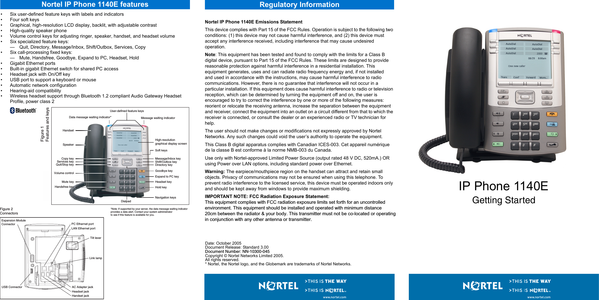
Wistron IPNTYS05 IP Phone with Bluetooth User Manual IP Phone 2033 Getting Started

Wistron Corporation IP Phone with Bluetooth IP Phone 2033 Getting Started

Users Manual

• Six user-defined feature keys with labels and indicators• Four soft keys• Graphical, high-resolution LCD display, backlit, with adjustable contrast• High-quality speaker phone• Volume control keys for adjusting ringer, speaker, handset, and headset volume• Six specialized feature keys:— Quit, Directory, Message/Inbox, Shift/Outbox, Services, Copy • Six call-processing fixed keys: — Mute, Handsfree, Goodbye, Expand to PC, Headset, Hold • Gigabit Ethernet ports• Built-in gigabit Ethernet switch for shared PC access• Headset jack with On/Off key • USB port to support a keyboard or mouse• Automatic network configuration• Hearing-aid compatibility• Wireless headset support through Bluetooth 1.2 compliant Audio Gateway Headset Profile, power class 2Nortel IP Phone 1140E Emissions StatementThis device complies with Part 15 of the FCC Rules. Operation is subject to the following two conditions: (1) this device may not cause harmful interference, and (2) this device must accept any interference received, including interference that may cause undesired operation.Note: This equipment has been tested and found to comply with the limits for a Class B digital device, pursuant to Part 15 of the FCC Rules. These limits are designed to provide reasonable protection against harmful interference in a residential installation. This equipment generates, uses and can radiate radio frequency energy and, if not installedand used in accordance with the instructions, may cause harmful interference to radio communications. However, there is no guarantee that interference will not occur in a particular installation. If this equipment does cause harmful interference to radio or television reception, which can be determined by turning the equipment off and on, the user is encouraged to try to correct the interference by one or more of the following measures: reorient or relocate the receiving antenna, increase the separation between the equipment and receiver, connect the equipment into an outlet on a circuit different from that to which the receiver is connected, or consult the dealer or an experienced radio or TV technician for help.The user should not make changes or modifications not expressly approved by Nortel Networks. Any such changes could void the user’s authority to operate the equipment.This Class B digital apparatus complies with Canadian ICES-003. Cet appareil numérique de la classe B est conforme à la norme NMB-003 du Canada.Use only with Nortel-approved Limited Power Source (output rated 48 V DC, 520mA.) OR using Power over LAN options, including standard power over Ethernet.Warning: The earpiece/mouthpiece region on the handset can attract and retain small objects. Privacy of communications may not be ensured when using this telephone. To prevent radio interference to the licensed service, this device must be operated indoors only and should be kept away from windows to provide maximum shielding.IMPORTANT NOTE: FCC Radiation Exposure Statement:This equipment complies with FCC radiation exposure limits set forth for an uncontrolledenvironment. This equipment should be installed and operated with minimum distance20cm between the radiator & your body. This transmitter must not be co-located or operatingin conjunction with any other antenna or transmitter.IP Phone 1140EGetting StartedHandsfree keyHandsetUser-defined feature keysHigh-resolution graphical display screenNavigation keysServices keyCopy keyQuit/Stop keyMessage/Inbox keyShift/Outbox keyDirectory keyHold keyExpand to PC keyHeadset keyGoodbye keyVolume controlDialpadSoft keysSpeakerMessage waiting indicatorData message waiting indicator**Note: If supported by your server, the data message waiting indicator  provides a data alert. Contact your system administrator  to see if this feature is available for you.Mute keyFigure 1 Features and keysExpansion ModuleConnector PC Ethernet portLAN Ethernet portLink lampTilt leverUSB Connector AC Adapter jackHeadset jackHandset jackFigure 2 ConnectorsRegulatory Informationwww.nortel.com www.nortel.comNortel IP Phone 1140E featuresDate: October 2005Document Release: Standard 3.00Document Number: NN-10300-045Copyright © Nortel Networks Limited 2005.All rights reserved.* Nortel, the Nortel logo, and the Globemark are trademarks of Nortel Networks.
Step 1: Remove the stand cover. Pull upward on the center catch as indicated in Figure 3, and remove the stand cover. The cable routing tracks are now accessible.Step 2: Connect the AC power adapter (optional). Connect the adapter to the AC adapter jack in the bottom of the phone. Form a small bend in the cable, and then thread the adapter cord through the channels in the stand. Warning: Use your IP Phone 1140E with the approved Nortel AC Adapter (model #N0023000) for this model of phone only.Note 1: Your IP Phone 1140E supports both AC power and Power over Ethernet options, including IEEE 802.3af standard power. To use local AC power, the optional AC adapter can be ordered separately. To use Power over Ethernet, where power is delivered over the CAT-5 cable, the LAN must support Power over Ethernet, and an AC adapter is not required.Note 2: You must use CAT-5e (or later) cables if you want to use gigabit Ethernet.Step 3: Install the handset. Connect the end of the handset cable with the short straight section into the handset. Connect the end of the handset cable with the long straight section to the back of the phone, using the RJ-9 handset jack marked with the symbol +. Form a small bend in the cable, and then thread the handset cord through the channels in the stand so that it exits behind the handset on the right side, in the Handset cord exit marked with the symbol + in the stand base, as shown in Figure 3.Step 4: Install the headset (optional). If you are installing a headset, plug the connector into the RJ-9 headset jack marked with the symbol ) on the back of the phone, and thread the headset cord along with the handset cord through the channels in the stand, so that the headset cord exits the channel marked with the symbol ).Step 5: Install the Ethernet cable. Connect one end of the supplied Ethernet cable to the back of your phone using the RJ-45 connector marked with the symbol %, and thread the network cable through the channel marked with the symbol %. Step 6: Install the Ethernet cable connecting the PC to the phone (optional). If you are connecting your PC Ethernet through the phone, connect one end of the PC Ethernet cable to your phone using the RJ-45 connector marked with the symbol (, and thread it through the channel marked with the symbol (. Connect the other end to the LAN connector on the back of your PC.Step 7: Install additional cables. If applicable, plug in optional USB devices. Connect the Ethernet cable to the LAN Ethernet connection. If you are using an AC power adapter, plug the adapter into an AC outlet. Step 8: Wall-mount your phone (optional). Your IP Phone 1140E can be mounted either by: (method A) using the mounting holes on the bottom of the phone stand, or (method B) using a traditional-style wall-mount box with RJ-45 connector and 15-cm (6-inch) RJ-45 cord (not provided).Complete steps 1-7, as needed, before you wall-mount your phone:Method A: Press the wall-mount lever, and pull the phone away from the stand, as shown in Figure 5.Using the stand cover (the part you removed in step 1), mark the wall-mount holes by pressing the bottom of the stand cover firmly against the wall in the location where you wish to install the phone. Four small pins on the bottom of the stand cover make marks on the wall. Use the marks as a guideline for installing the wall-mount screws (not provided). Install the screws so that they protrude 3 mm (1/8 inch) from the wall, and then install the phone stand mounting holes over the screw heads as indicated in Figure 4 (Method A). You may need to remove the phone from the wall to adjust the lower screws. When the lower screws are snug, install the phone on the mounting screws, and then tighten the top screws.Method B: Attach the 15-cm (6-inch) CAT5e cable, position the stand over the mounting rivets, and slide the phone down the wall so that the rivets fit into the slots on the stand, indicated in Figure 4 (Method B).Step 9: Replace the stand cover. Ensure that all cables are neatly routed and press the stand cover into place until you hear a clickStep 10: Put the phone in the wall-mount position (optional). If you wall-mounted your phone, put it in the wall-mount position by holding the Tilt Lever and pressing the phone towards the base until the phone is parallel with the base. Release the Tilt Lever and continue to push the phone towards the base until you hear an audible click. Ensure the phone is securely locked in position.IP Phone 1140E installationFigure 3 Removing the stand coverTilt LeverButtonCenterCatchHandsetcord exitIP Phone 1140E installationFigure 4 Cable routing tracksMethod AMethod BFigure 5 Rotate the phone until  the phone body is  parallel to the standWall-mount leverIP Phone 1140E controls:Controlling volumePress the up or down volume control key while using your handset, headset, or speaker to adjust the volume of the associated device.Answering a callLift the handset to answer a ringing call, or press the Handsfree or Headset key.Making a call with the handsetTo make a call using the primary line, lift the handset and enter the phone number on the dialpad. If your phone is programmed with several line keys, press a line key to select a line before calling. When your call is complete, press the Goodbye key or return the handset to the cradle.Making a call with the headset or using HandsfreePress the Headset or Handsfree key. Enter the phone number. When your call is complete, press the Goodbye key.Using Hold and MuteWhile on a call, press the Hold key to place your caller on hold. Press the line key to retrieve your call. The icons next to the line keys indicate held lines, while the Mute LED lights when Mute is active. Press the Mute key to mute your handset, headset, or speaker, allowing you to speak privately. Press the Mute key again to speak with your caller.Setting the contrastTo adjust the display contrast, press the Services key, select Telephone Options, and select Contrast Adjustment. Use the up/down arrow keys to change the setting. Setting the languageTo select the language used by the local menus, press the Services key twice quickly to open the local menu. Select 1. Preferences, select 2. Language, and use the up and down arrow keys to choose the language. Note: Use the Telephone Options menu to select the language used by call-server features. Consult the IP Phone 1140E User Guide for more information.IP Phone 1140E controlswww.nortel.comCaution: Your IP Phone 1140E is shipped with the base locked in position. To avoid damaging your phone, press the wall-mount lever, located just under the Handsfree key as indicated in Figure 5, to release the base and pull it away from the phone.

Navigation menu