Wistron LPM 802.11 bgn Hybrid Switch Module User Manual LPM V0 1 2011 August 18 rev
Wistron Corporation 802.11 bgn Hybrid Switch Module LPM V0 1 2011 August 18 rev
Wistron >
User Man_PU5-LPM_rev. 2

LPM WLAN MiniCard
2011/08/10
Naginata 1.1 LPM module
802.11 b/g/n Duplicity android switch Module
User Manual
Rev 0.1
2011.08.10
LPM 1.0 module
802.11 bgn Hybrid Switch Module
Wistron

LPM WLAN MiniCard
2011/08/10
FCC compliance Statement
Federal Communication Commission interference state-ment this equipment has been tested and found to comply
with the limits for a Class B digital device, pursuant to Part 15 of the FCC Rules. These limits are designed to pro-
vide reasonable protection against harmful interference in a residential instal-lation. This equipment generates, uses
and can radiate radio frequency energy and, if not installed and used in accordance with the instructions, may cause
harmful interference to radio communications. However, there is no guarantee that interfer-ence will not occur in a
particular installation. If this equipment does cause harmful interference to radio or television recep-tion, which can
be determined by turning the equipment off and on, the user is encouraged to try to correct the interference by one of
the following measures:
-Reorient or relocate the receiving antenna.
-Increase the separation between the equipment and receiver.
-Connect the equipment into an outlet on a circuit different from that to which the receiver is connected.
-Consult the dealer or an experienced radio/TV technician for help.
This device complies with Part 15 of the FCC Rules. Operation is subject to the following two conditions:
(1) This device may not cause harmful interference, and
(2) This device must accept any interference received, includ-ing interference that may cause undesired operation.
You are cautioned that changes or modifications not expressly approved by the party responsible for compliance
could void your
authority to operate the equipment.
RF exposure warning: The equipment complies with RF exposure limits set forth for an uncontrolled environment.
The antenna(s) used for this transmitter must not be co-located or operating in conjunction with any other antenna or
transmitter.

For Taiwan 警語:
經型式認證合格之低功率射頻電機,非經許可,公司、商號或使用者均不得擅
自變更頻率、加大功率或變更原設計之特性及功能。
低功率射頻電機之使用不得影響飛航安全及干擾合法通信;經發現有干擾現象
時,應立即停用,並改善至無干擾時方得繼續使用。前項合法通信,指依電信
法規定作業之無線電通信。低功率射頻電機須忍受合法通信或工業、科學及醫
療用電波輻射性電機設備之干擾。
Note: 1. 本模組於取得認證後將依規定於模組本體標示審驗合格標籤 2. 系統廠
商應於平台上標示「本產品內含射頻模組: XXXyyyLPDzzzz-x (NCC ID) 」字
樣

LPM WLAN MiniCard
ii
Table of contents
CHAPTER 1........................................................................................................ 2
CHAPTER 2........................................................................................................ 2
CHAPTER 3........................................................................................................ 2
APPENDIX A ...................................................................................................... 2

LPM WLAN MiniCard=rd
1
Chapter 1
Introduction
LPM module is a WLAN module with a BROADCOM single-chip BCM4319. The WLAN circuitry works
with the host via the Secure Digital I/O (SDIO) interface. Being able to support the 802.11n standard in an
1x1 40MHz bandwidth mode, the data rates can be as high as 150Mbps.
Features and Benefits
• One Tiny Size Module Supporting
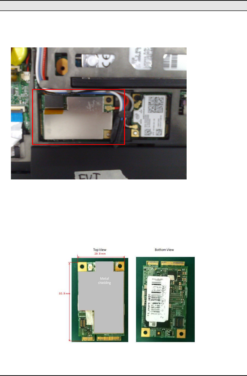
Only takes a small 50.95 (W) x 30 (D) x 4.75(T) footprint.
• Seamless Wireless Connectivity
The modules support the IEEE 802.11b/g standards and 802.11n at 1x1 MIMO mode for high speed
and transparent connectivity against most home and business APs and all public hot spots around
the world.
• Up-to-Date, High-Level Security
WEP and WPA are supported to ensure maximum WiFi data privacy.
• Dynamic Rate Shifting
Wireless transmission speed is automatically adjusted on the basis of signal strength to achieve
maximum availability and link reliability.
• WiFi and Cellular Coexistence
Advanced WiFi coexistence logics are included. That is one separated antenna for WLAN. It also
coexists with cellular GSM/UMTS.
• Embedded Oscillator
Oscillator is embedded.
.

LPM WLAN MiniCard
2
What is Wireless LAN?
Wireless Local Area Network (WLAN) systems offer a great number of advantages over tradi-
tional wired systems. WLANs are flexible and easy to setup and manage. They are also more
economical than wired LAN systems.
Using radio frequency (RF) technology, WLANs transmit and receive data through the air.
WLANs combine data connectivity with user mobility. For example, users can roam from a con-
ference room to their office without being disconnected from the LAN.
Using WLANs, users can conveniently access shared information, and network administrators
can configure and augment networks without installing or moving network cables.
WLAN technology provides users with many convenient and cost saving features:
• Mobility: WLANs provide LAN users with access to real-time information anywhere in their
organization, providing service opportunities that are impossible with wired networks.
• Ease of Installation: Installing is easy for novice and expert users alike, eliminating the
need to install network cables in walls and ceilings.
• Scalability: WLANs can be configured in a variety of topologies to adapt to specific appli-
cations and installations. Configurations are easily changed and range from peer-to-peer
networks suitable for a small number of users to full infrastructure networks of thousands
of users roaming over a broad area.

—Introduction
3
LAN Modes
Wireless LANs can be configured in one of two ways:
Table 1: LAN modes
Ad-hoc
Networking Also known as a peer-to-peer network, an ad-hoc net-
work is one that allows all workstations and computers
in the network to act as servers to all other users on
the network. Users on the network can share files,
print to a shared printer, and access the Internet with a
shared modem. However, with ad-hoc networking,
users can only communicate with other wireless LAN
computers that are in the wireless LAN workgroup, and
are within range.
Infrastructure
Networking Infrastructure networking differs from ad-hoc network-
ing in that it includes an access point. Unlike the ad-
hoc structure where users on the LAN contend the
shared bandwidth, on an infrastructure network the
access point can manage the bandwidth to maximize
bandwidth utilization.
Additionally, the access point enables users on a wire-
less LAN to access an existing wired network, allowing
wireless users to take advantage of the wired networks
resources, such as Internet, email, file transfer, and
printer sharing.
Infrastructure networking has the following advantages
over ad-hoc networking:
• Extended range: each wireless LAN computer
within the range of the access point can commu-
nicate with other wireless LAN computers within
range of the access point.
• Roaming: the access point enables a wireless
LAN computer to move through a building and
still be connected to the LAN.
• Wired to wireless LAN connectivity: the access
point bridges the gap between wireless LANs and
their wired counterparts.
Notes on wireless LAN configuration
When configuring a wireless LAN (WLAN), be sure to note the following points:
• Optimize the performance of the WLAN by ensuring that the distance between access
points is not too far. In most buildings, WLAN cards operate within a range of 100 ~ 300
feet, depending on the thickness and structure of the walls.
• Radio waves can pass through walls and glass but not metal. If there is interference in
transmitting through a wall, it may be that the wall has reinforcing metal in its structure. In-
stall another access point to circumvent this problem.
• Floors usually have metal girders and metal reinforcing struts that interfere with WLAN
transmission.
LPM WLAN MiniCard
4
Chapter 2
Hardware Installation
This chapter covers how to installing the Wireless card in your system.
Hardware description
The Wireless MiniCard has a SDIO interface for attaching to the system.
And this module has IPEX connector to connect to external antenna.
Outlook
Following is the Minicard outlook
Figure 1: LPM module outlook
LPM module
LPM WLAN MiniCard
5
Chapter 3
Using the Wireless Utility
This module also come with a wireless utility, following describe how to use the utility.
Configuration Utility for 802.11b/g/n
To experience the IMM wireless, please make sure you have the Switch Manger installed. After you have the
Switch Manger installed, IMM card will be ready for you to enjoy the wireless connectivity.
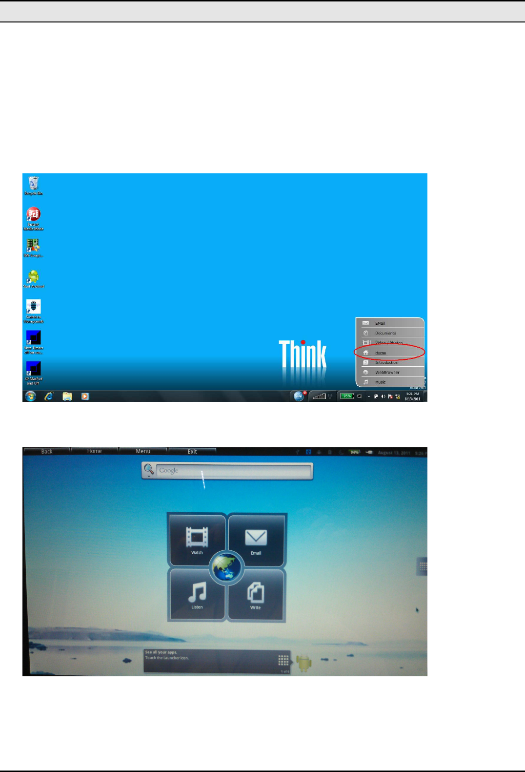
1. Select the “Home” option as below to enable IMM mode.
2. Switch Manger may ask you whether you are ready to switch to IMM mode, choose “Yes” to switch. When switch-
ed to IMM mode, IMM may have turned off screen for better battery life. Press “Insert” key to unlock it.
3. This is the Home desktop of IMM mode, just as a normal Android desktop.
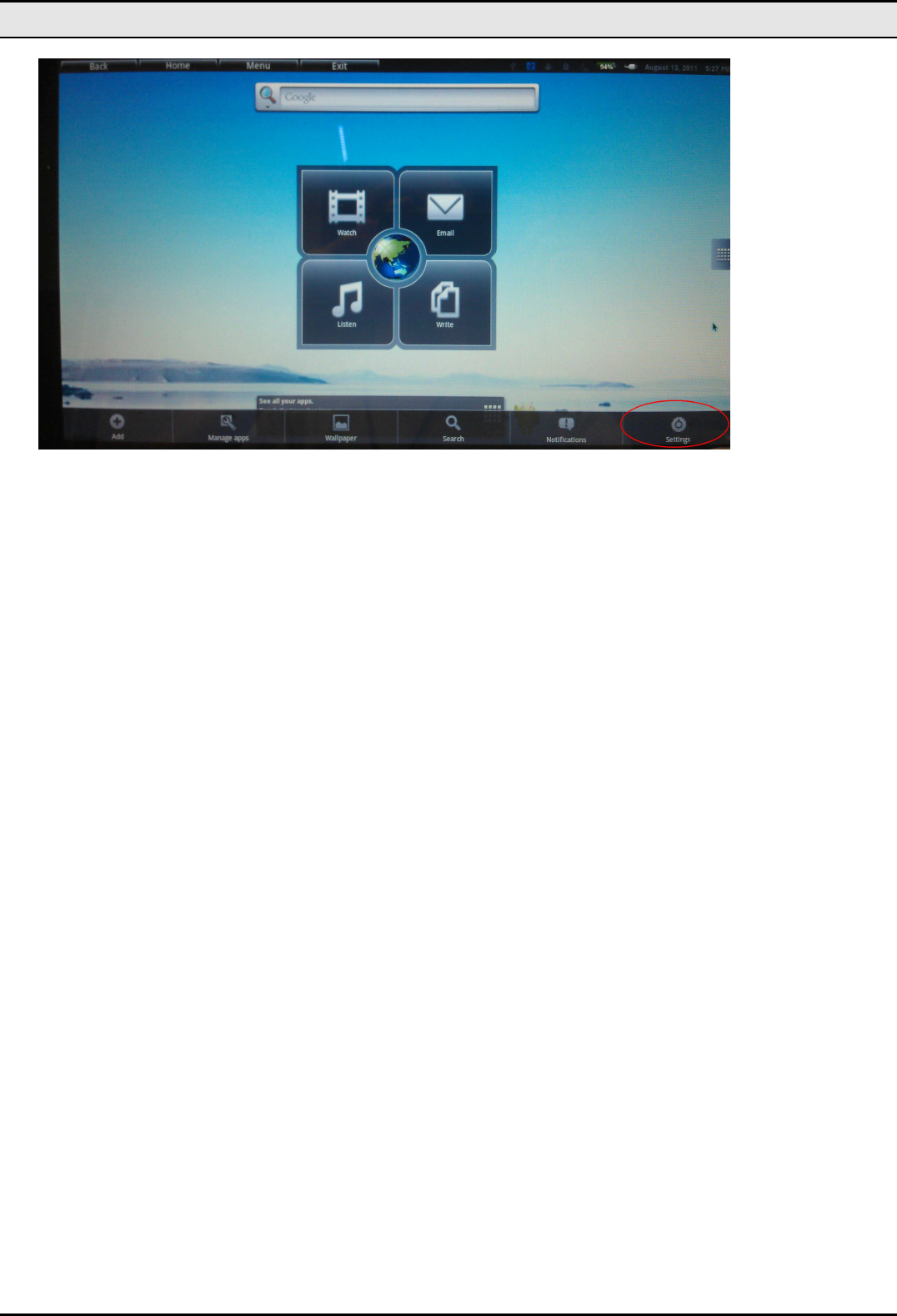
4. To enable wireless connectivity, please “Insert” key to show the menu.
5. Select “Setting” as below.
LPM WLAN MiniCard
6
6. Select “Wireless & networks”
7. Click “Wi-Fi” checkbox to enable WiFi module.
8. To connect to one WiFi access point, select “WiFi settings” for more options.
9. Once you get IMM paired with one access point, IMM is ready to connect.

LPM WLAN MiniCard
7
Appendix A
Specifications
Model Number Naginata 1.1 LPM module
Product Type 802.11b/g/n wlan Module
Interface(s) WC160/WC160M: SDIO
Embedded MAC Address WU160M and WC160M only
Main Chip(s) BCM4319
Package 68-pin LGA
Wireless Standard(s) IEEE 802.11b/g/n
Spreading IEEE 802.11b DSSS and 802.11g/n OFDM
Operating Frequency 2412~2462MHz ISM band
Antenna One antenna duplexing Tx and Rx
Number of Channels 11 (US), 13 (EU), 14 (Japan)
Data Rates 802.11n: up to 150Mbps
802.11g: 54Mbps with fallback to 48,36,24,18,12,9 and
6Mbps
802.11b: 11Mbps with fallback to 5.5, 1 and 1Mbps
Modulation Schemes 802.11g/n:
64QAM (150/135/120/72.2/65/57.8/54/48Mbps),
16QAM (90/60/43.3/36/28.9/24Mbps),
QPSK (45/30/21.7/18/14.7/12Mbps),
BPSK (15/9/7.2/6Mbps)
802.11b:
CCK (11/5.5Mbps),DQPSK (2Mbps),DBPSK (1Mbps)
Tx Power (typical) 13dBm for 802.11g/n
15dBm for 802.11b
Rx Sensitivity (typical) -72dBm for 54Mbps @ 10% PER
-87dBm for 11Mbps @ 8% PER
Media Access Protocol CSMA/CA with ACK
Operating System Support Android 3.0
Power Requirements 2.3-5.5volts
Power Saving mode (DTIM=1) : 5.6mA (typical)
Tx mode : 290mA (typical)
Rx mode : 140mA (typical)
Dimensions 50.95 (W) x 30 (D) x 4.75(T) mm (typical)
Regulatory Conformance EMI: FCC Part 15b, Part 15c
Europe EN 301 489, EN 300 328
Safety : US : UL 60950-1
Europe : EN 60950-1, EN 50360-1 (SAR)
IEC60950-1
RoHS Compliance Yes
Operating Temperatures 0 – 55
o
C
18.0dBm (for 802.11b) 23.0dBm (for802.11g)
23.0dBm(for 802.11n(20MHz)) 21.0dBm(for 802.11n(40MHz))
LPM 1.0 module

LPM WLAN MiniCard
8
j/31U.S. Regulatory Wireless Notice
Federal Communication Commission Interference Statement
This equipment has been tested and found to comply with the limits for a Class B digital device, pur-
suant to Part 15 of the FCC Rules. These limits are designed to provide reasonable protection
against harmful interference in a residential installation. This equipment generates, uses and can ra-
diate radio frequency energy and, if not installed and used in accordance with the instructions, may
cause harmful interference to radio communications. However, there is no guarantee that interfer-
ence will not occur in a particular installation. If this equipment does cause harmful interference to
radio or television reception, which can be determined by turning the equipment off and on, the user
is encouraged to try to correct the interference by one of the following measures:
- Reorient or relocate the receiving antenna.
- Increase the separation between the equipment and receiver.
- Connect the equipment into an outlet on a circuit different from that
to which the receiver is connected.
- Consult the dealer or an experienced radio/TV technician for help.
FCC Caution: Any changes or modifications not expressly approved by the party responsible for
compliance could void the user's authority to operate this equipment.
This device complies with Part 15 of the FCC Rules. Operation is subject to the
following two conditions: (1) This device may not cause harmful interference, and (2)
this device must accept any interference received, including interference that may
cause undesired operation.
IMPORTANT NOTE:
FCC Radiation Exposure Statement:
This equipment complies with FCC radiation exposure limits set forth for an uncontrolled environment.
This equipment should be installed and operated with minimum distance 20cm between the radiator
& your body.
This transmitter must not be co-located or operating in conjunction with any other antenna or trans-
mitter.

Appendix B Error Messages of Enabler Program
9
This device is intended only for OEM integrators under the following conditions:
1) The antenna must be installed such that 20 cm is maintained between the antenna and users,
and
2) The transmitter module may not be co-located with any other transmitter or antenna,
3) For all products market in US, OEM has to limit the operation channels in CH1 to CH11 for
2.4G band by supplied firmware programming tool. OEM shall not supply any tool or info to the
end-user regarding to Regulatory Domain change.
As long as 3 conditions above are met, further transmitter test will not be required. However, the
OEM integrator is still responsible for testing their end-product for any additional compliance re-
quirements required with this module installed
IMPORTANT NOTE: In the event that these conditions can not be met (for example certain laptop
configurations or co-location with another transmitter), then the FCC authorization is no longer
considered valid and the FCC ID can not be used on the final product. In these circumstances, the
OEM integrator will be responsible for re-evaluating the end product (including the transmitter) and
obtaining a separate FCC authorization.
End Product Labeling
This transmitter module is authorized only for use in device where the antenna may be installed such
that 20 cm may be maintained between the antenna and users. The final end product must be la-
beled in a visible area with the following: “Contains FCC ID: PU5-LPM”.
Manual Information To the End User
The OEM integrator has to be aware not to provide information to the end user regard-
ing how to install or remove this RF module in the user’s manual of the end product
which integrates this module.
The end user manual shall include all required regulatory information/warning as show in this manual.
Industry Canada statement:
Industry Canada statement:Industry Canada statement:
Industry Canada statement:
This device complies with RSS-210 of the Industry Canada Rules. Operation is subject to the following two
conditions: (1) This device may not cause harmful interference, and (2) this device must accept any interfer-
ence received, including interference that may cause undesired operation.
Ce dispositif est conforme à la norme CNR-210 d'Industrie Canada applicable aux appareils radio exempts
de licence. Son fonctionnement est sujet aux deux conditions suivantes: (1) le dispositif ne doit pas
produire de brouillage préjudiciable, et (2) ce dispositif doit accepter tout brouillage reçu, y compris un
brouillage susceptible de provoquer un fonctionnement indésirable.
=========================================================
This device is intended only for OEM integrators under the following conditions:
This device is intended only for OEM integrators under the following conditions:This device is intended only for OEM integrators under the following conditions:
This device is intended only for OEM integrators under the following conditions: (For module device use)
(For module device use) (For module device use)
(For module device use)
1) The antenna must be installed such that 20 cm is maintained between the antenna and users, and
2) The transmitter module may not be co-located with any other transmitter or antenna,
.
2

LPM WLAN MiniCard
10
3) For all products market in Canada, OEM has to limit the operation channels in CH1 to CH11 for 2.4G band
by supplied firmware programming tool. OEM shall not supply any tool or info to the end-user regarding to
Regulatory Domain change.
As long as 3 conditions above are met, further transmitter test will not be required. However, the OEM inte-
grator is still responsible for testing their end-product for any additional compliance requirements required
with this module installed.
Cet appareil est conçu uniquement pour les intégrateurs OEM dans les conditions suivantes: (Pour utilisation de
dispositif module)
1) L'antenne doit être installée de telle sorte qu'une distance de 20 cm est respectée entre l'antenne et les
utilisateurs, et
2) Le module émetteur peut ne pas être coïmplanté avec un autre émetteur ou antenne,
3) Pour tous les produits vendus au Canada, OEM doit limiter les fréquences de fonctionnement CH1 à CH11
pour bandes de fréquences 2.4G grâce aux outils de microprogrammation fournis. OEM ne doit pas fournir
d'outil ou d'informations à l'utilisateur final en ce qui concerne le changement de réglementation de domaine.
Tant que les 3 conditions ci-dessus sont remplies, des essais supplémentaires sur l'émetteur ne seront pas
nécessaires. Toutefois, l'intégrateur OEM est toujours responsable des essais sur son produit final pour toutes
exigences de conformité supplémentaires requis pour ce module installé.
=========================================================
IMPORTANT NOTE:
IMPORTANT NOTE:IMPORTANT NOTE:
IMPORTANT NOTE:
In the event that these conditions can not be met (for example certain laptop configurations or co-location
with another transmitter), then the Canada authorization is no longer considered valid and the IC ID can not
be used on the final product. In these circumstances, the OEM integrator will be responsible for re-
evaluating the end product (including the transmitter) and obtaining a separate Canada authorization.
NOTE IMPORTANTE:
Dans le cas où ces conditions ne peuvent être satisfaites (par exemple pour certaines configurations
d'ordinateur portable ou de certaines co-localisation avec un autre émetteur), l'autorisation du Canada n'est
plus considéré comme valide et l'ID IC ne peut pas être utilisé sur le produit final. Dans ces circonstances,
l'intégrateur OEM sera chargé de réévaluer le produit final (y compris l'émetteur) et l'obtention d'une
autorisation distincte au Canada.
=========================================================
.
2
2
.

Appendix B Error Messages of Enabler Program
11
End Product Labeling
End Product LabelingEnd Product Labeling
End Product Labeling
This transmitter module is authorized only for use in device where the antenna may be installed such that
20 cm may be maintained between the antenna and users. The final end product must be labeled in a visible
area with the following: “Contains IC: 4182A-LPM”.
Plaque signalétique du produit final
Ce module émetteur est autorisé uniquement pour une utilisation dans un dispositif où l'antenne peut être
installée de telle sorte qu'une distance de 20cm peut être maintenue entre l'antenne et les utilisateurs. Le
produit final doit être étiqueté dans un endroit visible avec l'inscription suivante: "Contient des IC: 4182A-
LPM".
=========================================================
Manual Information To the End User
Manual Information To the End UserManual Information To the End User
Manual Information To the End User
The OEM integrator has to be aware not to provide information to the end user regarding how to install or
remove this RF module in the user’s manual of the end product which integrates this module.
The end user manual shall include all required regulatory information/warning as show in this manual.
Manuel d'information à l'utilisateur final
L'intégrateur OEM doit être conscient de ne pas fournir des informations à l'utilisateur final quant à la
façon d'installer ou de supprimer ce module RF dans le manuel de l'utilisateur du produit final qui intègre ce
module.
Le manuel de l'utilisateur final doit inclure toutes les informations réglementaires requises et
avertissements comme in