Wistron MS2133 MS2133 User Manual manual Part 3 of 3a
Wistron Corporation MS2133 manual Part 3 of 3a
Wistron >
Contents
2nd Revised manual
2 Customizing your computer
After learning the basics of your TravelMate computer, let’s get acquainted with the
advanced features of your computer. In this chapter, you will learn how to add
options, upgrade components for better performance, and customize your
computer.
Expanding through options
Your TravelMate offers you a complete mobile computing experience.
Connectivity options
Ports allow you to connect peripheral devices to your computer as you would with a desktop PC.
Fax/data modem
Some models have a built-in V.92 56Kbps software modem.
Warning! This modem port is not compatible with digital phone lines. Plugging this
modem into a digital phone line will damage the modem.
To use the fax/data modem port, connect a phone cable from the modem port to a telephone jack.
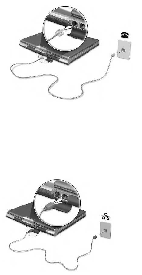
Start your communications software program. See your communications manual for instructions.
Built-in network feature
The built-in network feature allows you to connect your computer to an Ethernet-based (10/100 Mbps)
network.
To use the network feature, connect an Ethernet cable from the network jack on the rear of the computer to a
network jack or hub on your network.
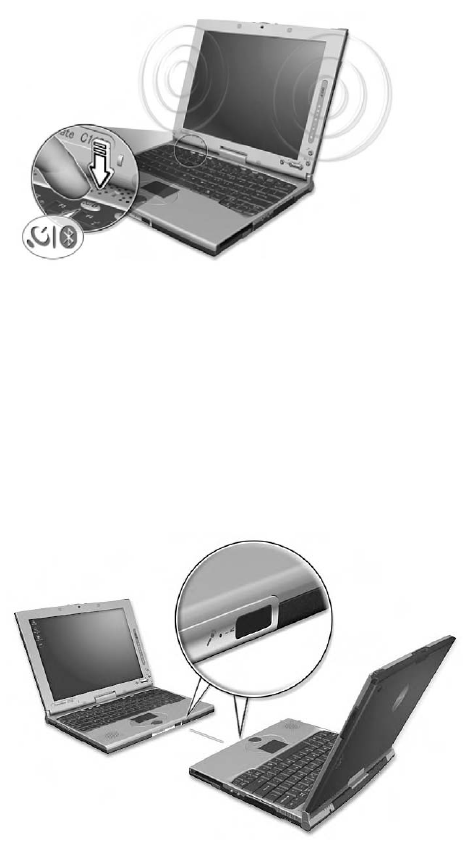
Wireless communication
Available on select models, the wireless communication feature allows you to communicate with other
wireless-equipped devices via 802.11b, 802.11a and/or Bluetooth protocols.
For more information on how to enable this feature, see “Launch Manager and wireless features” on page 51.
Fast infrared
The computer’s fast infrared (FIR) port allows you to do wireless data transfer with other IR-aware computers
and peripherals such as infrared printers. The infrared port can transfer data at speeds of up to four megabits
per second (Mbps) at a distance of up to one meter.
To use FIR, position two IR-aware devices such that their IR ports are no more than one meter apart and offset
no more than 15 degrees.
When the two computers are in position, simply begin the data transfer as you normally would. See your file
transfer software for details.
Universal Serial Bus
The Universal Serial Bus (USB 2.0) port is a high-speed serial bus which allows you to connect and
daisy-chain USB peripherals without taking up precious system resources. Your computer has two ports
available.
Connecting your optical drive
Connect the AC adapter and the USB cable to the rear of the optical drive (a). Plug the other end of the USB
cable to the computer (b). Connect the AC adapter to the power outlet (c).
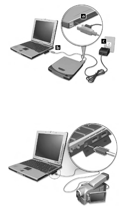
IEEE 1394
The computer’s fast IEEE 1394 port allows you to connect IEEE 1394 supported devices like a digital video
camera.
See your video or digital camera’s documentation for details.
PC Card slot
There is a type II CardBus PC Card slot found on the right side of the computer. This slot accepts
credit-card-sized cards that enhance the usability and expandability of the computer. These cards should
have a PC Card logo on them.
PC Cards (formerly PCMCIA) are add-on cards for portable computers, giving you expansion possibilities long
afforded by desktop PCs. Popular type II cards include flash memory, SRAM, fax/data modem, LAN and SCSI
cards. CardBus improves on the 16-bit PC card technology by expanding the bandwidth to 32 bits.
Note: Refer to your card’s manual for details on how to install and use the card and its functions.
Inserting a PC Card
Insert the card into the slot and make the proper connections (e.g., network cable), if necessary. See your
card manual for details.
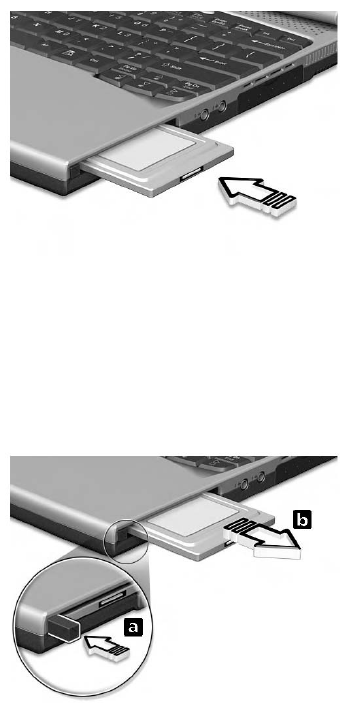
Ejecting a PC Card
Before ejecting a PC Card:
1Exit the application using the card.
2Left-click on the Safely Remove Hardware icon on the taskbar and stop the card operation.
3Press the slot eject button (a) to pop out the eject button; then press it again (a) to eject the card (b).
Upgrade options
Your computer delivers superior power and performance. However, some users and the applications they use
may demand more. This computer allows you to upgrade key components when you need increased
performance.
Note: Contact your authorized dealer if you decide to perform a key component upgrade.
Memory upgrade
Memory is expandable to 2 GB, employing PC2100 266 MHz industry standard DDR (Double Data Rate)
soDIMMs (Small Outline Dual Inline Memory Modules).
There are two memory slots on your computer, one of which is occupied by standard memory. You can
upgrade memory by installing a memory module into the available slot.
Installing memory
Follow these steps to install memory:
1Turn off the computer, unplug the AC adapter (if connected) and remove the battery pack. Then turn the
computer over to access its base.
2Remove the screw (a) from the memory cover; then lift up and remove the memory cover (b).
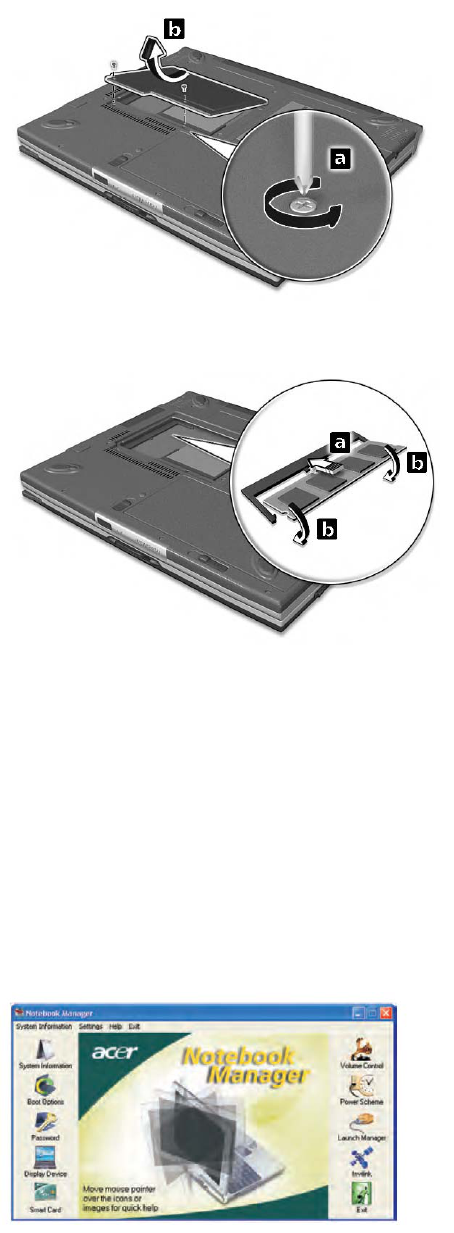
3Insert the memory module diagonally into the slot (a), then gently press it down (b) until it clicks into
place.
4Replace the memory cover and secure it with the screw.
The computer automatically detects and reconfigures the total memory size.
Notebook Manager
The computer has a built-in system setup program called Notebook Manager. The Windows-based Notebook
Manager allows you to set passwords, the startup sequence of the drives, power management and other
settings. It also shows current hardware configurations.
To start the Notebook Manager, press Fn-F2 or follow these steps:
1Click on Start, All Programs, then Acer.
2Select the Notebook Manager application to run the program.
Please click on Help for online help information.
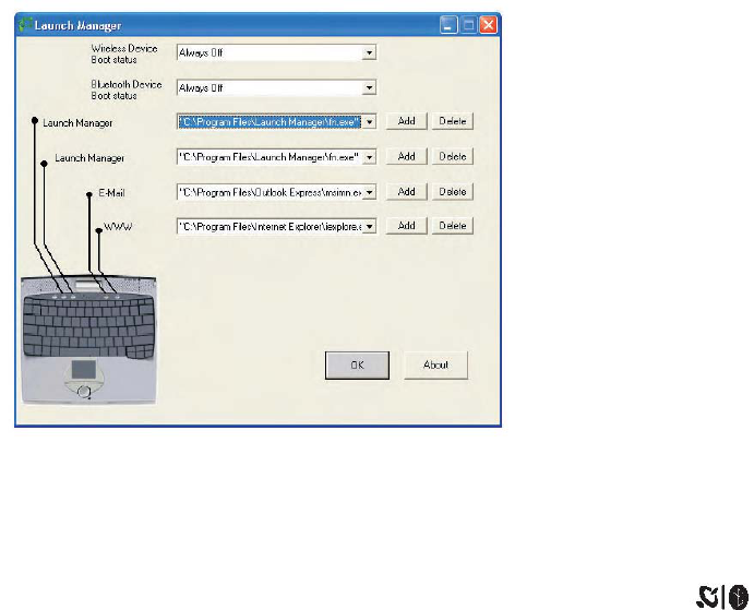
Launch Manager
Launch Manager allows you to set the four launch keys located above the keyboard. See “Launch keys” on
page 24 for the location of the launch key.
You can access the Launch Manager by clicking on Start, All Programs, and then Launch Manager to start
the application.
Launch Manager and wireless features
The boot status settings for Wireless Device (Wireless LAN) and Bluetooth Device determine if these wireless
features are enabled or disabled at startup.
You can manually switch on or off Wireless LAN and Bluetooth by pressing the button a certain
number of times. The sequence is as follows:
•Wireless LAN off, Bluetooth off
•Wireless LAN on, Bluetooth off (wireless status icon lights red)
•Wireless LAN off, Bluetooth on (wireless status icon flashes green)
•Wireless LAN on, Bluetooth on (wireless status icon lights red and flashes green)
Manually turning on the wireless features does not change the default boot status setting which is re-enabled
when you restart your computer.
BIOS Utility
The BIOS Utility is a hardware configuration program built into your computer’s BIOS (basic input/output
system).
Your computer is already properly configured and optimized, and you do not need to run this utility. However,
if you encounter configuration problems, you may need to run it.
To access the BIOS Utility, press F2 during the POST (power-on self-test) while the TravelMate logo is being
displayed.
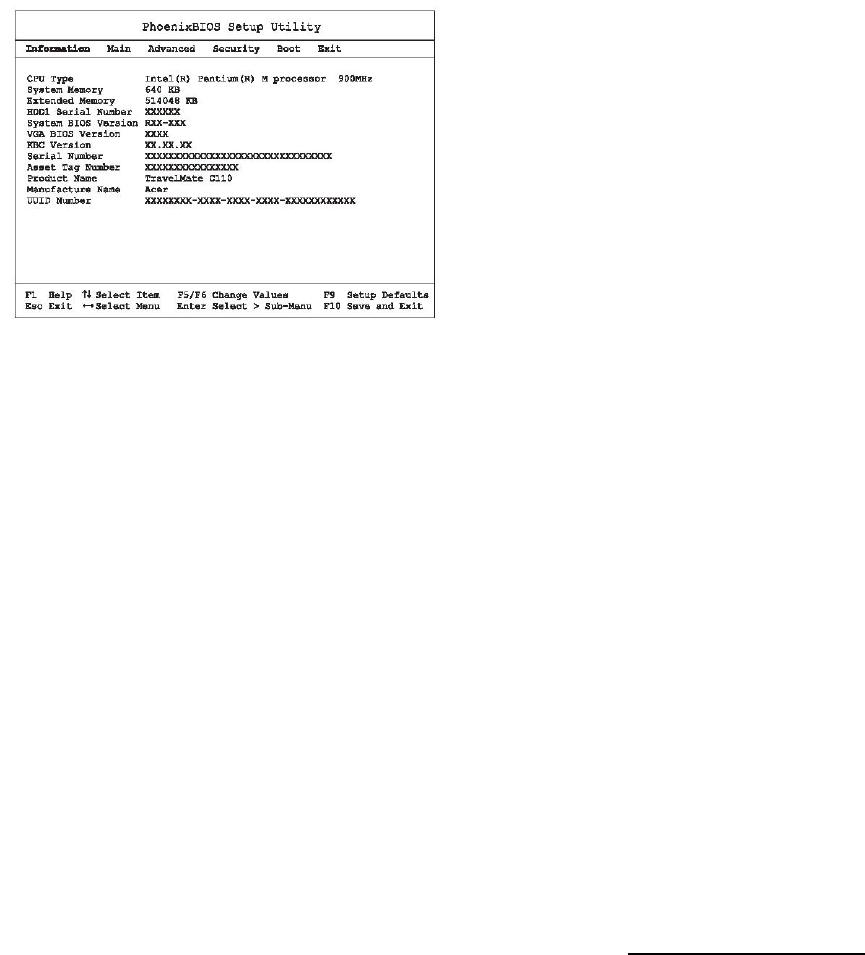
Note: The sample screen shown above is for your reference only. Actual values may differ.
For optimum settings, press F9 to load setup defaults. Then press F10 to save the changes and exit the BIOS
Utility.
3 Troubleshooting your
computer
This chapter instructs you on how to deal with common system problems. Read it
before calling a technician if a problem occurs. Solutions to more serious
problems require opening up the computer. Do not attempt to open the computer
by yourself. Contact your dealer or an authorized service center for assistance.
key link: www.acersupport.com
Frequently-asked questions
The following is a list of possible situations that may arise during the use of your computer. Easy answers and
solutions are provided for each one.
I pressed the power switch and opened the display, but the computer does not start or boot-up.
Look at the Power indicator (refer to “Indicators” on page 18):
•If it is not lit, no power is being applied to the computer. Check the following:
•If you are running on battery power, it may be low and unable to power the computer. Connect
the AC adapter to recharge the battery pack.
•Make sure that the AC adapter is plugged in properly to the computer and to the power outlet.
•If it is lit, check the following:
•Is a non-bootable (non-system) diskette in the floppy drive? Remove or replace it with a system
diskette and press Ctrl-Alt-Del to restart the system.
•The operating system files may be damaged or missing. Insert the startup disk you created during
Windows setup into the floppy drive and press Ctrl-Alt-Del to restart the system. This will diagnose your
system and make necessary fixes.
Nothing appears on the screen.
The computer’s power management system automatically blanks the screen to save power. Press any key to
turn the display back on.
If pressing a key does not turn the display back on, three things might be the cause:
•The brightness level might be too low. Press Fn-→ (increase) and Fn-← (decrease) to adjust the
brightness level.
•The display device might be set to an external monitor. Press the display toggle hot key Fn-F5 to toggle
the display back to the computer.
•If the Sleep indicator is lit, the computer is in Sleep mode. Press, slide, and release the power switch to
resume.
Image is not full-screen.
Make sure that the resolution is set to 1024x768 which the system supports natively. Right-click on your
Windows desktop and select Properties to bring up the Display Properties dialog box. Then click on the
Settings tab to make sure the resolution is set to the appropriate resolution. Resolutions lower than the
specified resolution are not full-screen on the computer or on an external monitor.
No audio is heard from the computer.
Check the following:
•The volume may be muted. In Windows, look at the volume control (speaker) icon on the taskbar. If it is
crossed-out, click on the icon and deselect the Mute option.
•The speakers may be turned off. Press Fn-F8 to turn the speakers on (this hot key also turns the
speakers off).
•The volume level may be too low. In Windows, look at the volume control icon on the taskbar. You can
also use the volume control buttons to adjust the volume. See “Hot keys” on page 21.
•If headphones, earphones or external speakers are connected to the line-out port on the computer’s right
panel, the internal speakers automatically turn off.
The keyboard does not respond.
Try attaching an external keyboard to the USB connector on the computer’s rear. If it works, contact your
dealer or an authorized service center as the internal keyboard cable may be loose.
The infrared port does not work.
Check the following:
•Make sure that the infrared ports of the two devices are facing each other (+/- 15 degrees) a maximum of
1 meter apart.
•Make sure that there is a clear path between the two infrared ports. Nothing should be blocking the ports.
•Make sure that you have the appropriate software running on both devices (for file transfers) or that you
have the appropriate drivers (for printing to an infrared printer).
•During the POST, press F2 to access the BIOS Utility and verify that the infrared port is enabled.
•Make sure that both devices are IrDA-compliant.
I want to set up my location to use the internal modem.
To properly use your communications software (e.g., HyperTerminal), you need to set up your location:
1Click on Start, Control Panel.
2Double-click on Phone and Modem Options.
3Begin setting up your location.
Refer to the Windows manual.
Troubleshooting tips
This notebook computer incorporates an advanced design that delivers onscreen error message reports to
help you solve problems.
•If the system reports an error message or an error symptom occurs, see “Error messages” on page 59.
Error messages
If you receive an error message, note the message and take the corrective action. The following table lists the
error messages in alphabetical order together with the recommended course of action.
Note: If your system displays one of the messages marked below with an asterisk (*), write down
the message and contact your dealer. If your system fails after you have made the changes in the Setup
menus, reset the computer, enter Setup and load the Setup defaults to correct the error.
Error Messages Corrective Action
0200 Failure Fixed Disk Fixed disk is not working or not configured
properly. Check to see if fixed disk is attached
properly. Run Setup. Find out if the fixed-disk
type is correctly identified.
0210 Stuck key Stuck key on keyboard.
0211 Keyboard error Keyboard not working.
0212 Keyboard Controller
Failed*
Keyboard controller failed test. May require
replacing keyboard controller.
0213 Keyboard locked -
Unlock key switch
Unlock the system to proceed.
0220 Monitor type does not
match CMOS - Run SETUP
Monitor type not correctly identified in Setup
0230 Shadow Ram Failed at
offset: nnnn* Shadow RAM failed at offset nnnn of the 64k
block at which the error was detected.
0231 System RAM Failed at
offset: nnnn* System RAM failed at offset nnnn of in the 64k
block at which the error was detected.
0232 Extended RAM Failed at
offset: nnnn* Extended memory not working or not configured
properly at offset nnnn.
0250 System battery is dead -
Replace and run SETUP
The CMOS clock battery indicator shows the
battery is dead. Replace the battery and run
Setup to reconfigure the system.
0251 System CMOS
checksum bad - Default
configuration used
System CMOS has been corrupted or modified
incorrectly, perhaps by an application program
that changes data stored in CMOS. The BIOS
installed Default Setup Values. If you do not
want these values, enter Setup and enter your
own values. If the error persists, check the
system battery or contact your dealer.
0260 System timer error* The timer test failed. Requires repair of system
board.
0270 Real time clock error* Real-Time Clock fails BIOS hardware test. May
require board repair.
0271 Check date and time
settings
BIOS found date or time out of range and reset
the Real-Time Clock. May require setting legal
date (1991-2099).
0280 Previous boot
incomplete - Default
configuration used
Previous POST did not complete successfully.
POST loads default values and offers to run
Setup. If the failure was caused by incorrect
values and they are not corrected, the next boot
will likely fail. On systems with control of wait
states, improper Setup settings can also
terminate POST and cause this error on the next
boot. Run Setup and verify that the wait-state
configuration is correct. This error is cleared the
next time the system is booted.
0281 Memory Size found by
POST differed from CMOS
Memory size found by POST differed from
CMOS.
02B0 Diskette drive A error
02B1 Diskette drive B error
Drive A: or B: is present but fails the BIOS POST
diskette tests. Check to see that the drive is
defined with the proper diskette type in Setup
and that the diskette drive is attached correctly.
02B2 Incorrect Drive A type -
run SETUP
Type of floppy drive A: not correctly identified in
Setup.
02B3 Incorrect Drive B type -
run SETUP
Type of floppy drive B: not correctly identified in
Setup.
02D0 System cache error -
Cache disabled
RAM cache failed and BIOS disabled the cache.
On older boards, check the cache jumpers. You
may have to replace the cache. See your dealer.
A disabled cache slows system performance
considerably.
02F0: CPU ID: CPU socket number for Multi-Processor error.
02F4: EISA CMOS not
writeable*
ServerBIOS2 test error: Cannot write to EISA
CMOS.
02F5: DMA Test Failed* ServerBIOS2 test error: Cannot write to
extended DMA (Direct Memory Access)
registers.
02F6: Software NMI Failed* ServerBIOS2 test error: Cannot generate
software NMI (Non-Maskable Interrupt).
02F7: Fail-Safe Timer NMI
Failed*
ServerBIOS2 test error: Fail-Safe Timer takes
too long.
device Address Conflict Address conflict for specified device.
Allocation Error for: device Run ISA or EISA Configuration Utility to resolve
resource conflict for the specified device.
Failing Bits: nnnn* The hex number nnnn is a map of the bits at the
RAM address which failed the memory test.
Each 1 (one) in the map indicates a failed bit.
See errors 230, 231, or 232 above for offset
address of the failure in System, Extended, or
Shadow memory.
Invalid System Configuration
Data
Problem with NVRAM (CMOS) data.
I/O device IRQ conflict I/O device IRQ conflict error.
One or more I2O Block
Storage Devices were
excluded from the Setup Boot
Menu
There was not enough room in the IPL table to
display all installed I2O block-storage devices.
Operating system not found Operating system cannot be located on either
drive A: or drive C:. Enter Setup and see if fixed
disk and drive A: are properly identified.
Parity Check 1 nnnn* Parity error found in the system bus. BIOS
attempts to locate the address and display it on
the screen. If it cannot locate the address, it
displays nnnn. Parity is a method for checking
errors in binary data. A parity error indicates that
some data has been corrupted.
Parity Check 2 nnnn* Parity error found in the I/O bus. BIOS attempts
to locate the address and display it on the
screen. If it cannot locate the address, it displays
nnnn.
Press <F1> to resume, <F2>
to Setup, <F3> for previous
Displayed after any recoverable error message.
Press <F1> to start the boot process or <F2> to
enter Setup and change the settings. Press
<F3> to display the previous screen (usually an
initialization error of an Option ROM, i.e., an
add-on card). Write down and follow the
information shown on the screen.
Run the I2O Configuration
Utility
One or more unclaimed block storage devices
have the Configuration Request bit set in the
LCT. Run an I2O Configuration Utility (e.g. the
SAC utility).
If you still encounter problems after going through the corrective measures, please contact your dealer or an
authorized service center for assistance. Some problems may be solved using the BIOS Utility.
Requesting service
International Traveler’s Warranty (ITW)
Your computer is backed by an International Traveler’s Warranty (ITW) that gives you security and peace of
mind when traveling. Our worldwide network of service centers are there to give you a helping hand.
An ITW passport comes with your computer. This passport contains all you need to know about the ITW
program. A list of available, authorized service centers are in this handy booklet. Read this passport
thoroughly.
Always have your ITW passport on hand, especially when you travel to receive the benefits from our support
centers. Place your proof-of-purchase in the flap located inside the front cover of the ITW passport.
If the country you are traveling in does not have an Acer-authorized ITW service site, you can still get in
contact with our offices worldwide.
There are three ways to access Acer for technical support and information:
•Internet service worldwide, visit http://www.acersupport.com/
•Telephone support in the United States and Canada, call 1-800-816-2237
•Technical support numbers in various countries
You can view a list of technical support numbers by following these steps:
1Click on Start, Settings, Control Panel.
2Double-click on System.
3Click on the Support Information button.
Before you call
Please have the following information available when you call Acer for online service, and please be at your
computer when you call. With your support, we can reduce the amount of time a call takes and help solve your
problems efficiently.
If there are error messages or beeps reported by your computer, write them down as they appear on the
screen (or the number and sequence in the case of beeps).
If you haven’t registered your notebook computer, you will be required to register during your first call to Acer.
You are required to provide the following information:
Name:________________________________________
Address:______________________________________
______________________________________________
Telephone number:____________________________
Machine and model type:_______________________
Serial number:_________________________________
Date of purchase:______________________________
This appendix lists the general specifications of your computer.
Microprocessor platform
•Intel® Centrino™ Mobile Technology
•Intel® Pentium® M Processor with 1 MB level 2 cache
•Intel® 855GM chipset family
•Intel® PRO/wireless network connection
Memory
•Main memory expandable to 2 GB
•Dual 200-pin soDIMM sockets supporting PC2100 DDR (Double Data Rate) memory running at 266 MHz
•512 KB Flash ROM BIOS
Data storage
•One 9.5mm, high-capacity, Enhanced-IDE hard disk
Display and video
•10.4"Thin-Film Transistor (TFT) liquid-crystal display (LCD) displaying 32-bit true-color at 1024x768
eXtended Graphics Array (XGA) resolution
•Integrated VGA with DVMT support
•3D capabilities
•Simultaneous LCD and CRT display support
•Dual display capability
•Tablet mode for LCD panel (Rotatable display)
Audio
•16-bit AC’ 97 PCI stereo audio with built-in wavetable synthesizer
•Built-in speaker and microphone
•Sound Blaster Pro and Windows Sound System-compatible
•Separate audio ports for headphone-out and line-in devices
Keyboard and pointing device
•Acer FineTouch keyboard
•Ergonomically-centered touchpad pointing device with scroll function
•Electromagnetic resonance (EMR) stylus for pen-based input
I/O ports
•Built-in:
•One type II/I CardBus PC Card slot
•One RJ-11 phone jack
•One RJ-45 LAN jack
•One DC-in jack (AC adapter)
•One external monitor port
•One speaker/headphone-out jack
•One line-in jack
•One FIR wireless communications port (IrDA-compliant)
•Two USB 2.0 ports
•One IEEE 1394 port
•One expansion connector
Weight and dimensions
•3.2 lbs (1.40 kg)
•257 (W) x 216 (D) x 29.7 (H) mm
Environment
•Temperature
•Operating: 10°C ~ 35°C
•Non-operating: -20°C ~ 60°C
•Humidity (non-condensing)
•Operating: 20% ~ 80% RH
•Non-operating: 20% ~ 80% RH
System
•Microsoft Windows XP Tablet PC Edition
•ACPI support
•DMI 2.0-compliant
•LDCM 6.0 support
Power
•Battery pack
•26 WattHour Li-ion main battery pack
•Smart battery management technology
•1.5-hour rapid charge/2.5-hour charge-in-use
•AC adapter
•50-Watt
•Auto sensing 100~240Vac, 50~60Hz
Options
•Memory upgrade modules
•Higher-capacity hard disk drive
•USB optical drive
•USB floppy disk drive
•IEEE 1394 optical drive
•Additional AC adapter
•Additional Li-ion battery pack
•External battery charger
•Full size EMR pen with eraser
•EMR stylus
•Bluetooth/Modem combo module
•802.11b, 802.11a, or 802.11a/b wireless LAN module
This appendix lists the general notices of your computer.
FCC notice
This device has been tested and found to comply with the limits for a Class B digital device pursuant to Part 15 of the FCC
Rules. These limits are designed to provide reasonable protection against harmful interference in a residential installation.
This device generates, uses, and can radiate radio frequency energy and, if not installed and used in accordance with the
instructions, may cause harmful interference to radio communications.
However, there is no guarantee that interference will not occur in a particular installation. If this device does cause harmful
interference to radio or television reception, which can be determined by turning the device off and on, the user is
encouraged to try to correct the interference by one or more of the following measures:
•Reorient or relocate the receiving antenna
•Increase the separation between the device and receiver
•Connect the device into an outlet on a circuit different from that to which the receiver is connected
•Consult the dealer or an experienced radio/television technician for help
Notice: Shielded cables
All connections to other computing devices must be made using shielded cables to maintain compliance with FCC
regulations.
Notice: Peripheral devices
Only peripherals (input/output devices, terminals, printers, etc.) certified to comply with the Class B limits may be attached to
this equipment. Operation with non-certified peripherals is likely to result in interference to radio and TV reception.
Caution
Changes or modifications not expressly approved by the manufacturer could void the user’s authority, which is granted by
the Federal Communications Commission, to operate this computer.
Use conditions
This part complies with Part 15 of the FCC Rules. Operation is subject to the following two conditions: (1) this device may
not cause harmful interference, and (2) this device must accept any interference received, including interference that may
cause undesired operation.
Notice: Canadian users
This Class B digital apparatus meets all requirements of the Canadian Interference-Causing Equipment Regulations.
Remarque à l’intention des utilisateurs canadiens
Cet appareil numérique de la classe B respected toutes les exigences du Règlement sur le matériel brouilleur du Canada.
Modem notices
FCC
This equipment complies with Part 68 of the FCC rules. Located on the bottom side of the modem is a label that contains,
among other information, the FCC Registration Number and Ringer Equivalence Number (REN) for this equipment. Upon
request, you must provide this information to your telephone company.
If your telephone equipment causes harm to the telephone network, the telephone company may discontinue your service
temporarily. If possible, they will notify you in advance. But, if advance notice is not practical, you will be notified as soon as
possible. You will also be informed of your right to file a complaint with the FCC.
Your telephone company may make changes in its facilities, equipment, operations, or procedures that could affect the
proper functioning of your equipment. If they do, you will be notified in advance to give you an opportunity to maintain
uninterrupted telephone service.
If this equipment should fail to operate properly, disconnect the equipment from the phone line to determine if it is causing
the problem. If the problem is with the equipment, discontinue use and contact your dealer or vendor.
TBR 21
This equipment has been approved [Council Decision 98/482/EC - “TBR 21”] for pan-European single terminal connection to
the Public Switched Telephone Network (PSTN). However, due to differences between the individual PSTNs provided in
different countries, the approval does not, of itself, give an unconditional assurance of successful operation on every PSTN
termination point. In the event of problems, you should contact your equipment supplier in the first instance.
Important safety instructions
Read these instructions carefully. Save these instructions for future reference.
1Follow all warnings and instructions marked on the product.
2Unplug this product from the wall outlet before cleaning. Do not use liquid cleaners or aerosol cleaners. Use a damp
cloth for cleaning.
3Do not use this product near water.
4Do not place this product on an unstable cart, stand, or table. The product may fall, causing serious damage to the
product.
5Slots and openings in the cabinet and the back or bottom are provided for ventilation; to ensure reliable operation of
the product and to protect it from overheating, these openings must not be blocked or covered. The openings should
never be blocked by placing the product on a bed, sofa, rug, or other similar surface. This product should never be
placed near or over a radiator or heat register, or in a built-in installation unless proper ventilation is provided.
6This product should be operated from the type of power indicated on the marking label. If you are not sure of the type
of power available, consult your dealer or local power company.
7Do not allow anything to rest on the power cord. Do not locate this product where persons will walk on the cord.
8If an extension cord is used with this product, make sure that the total ampere rating of the equipment plugged into the
extension cord does not exceed the extension cord ampere rating. Also, make sure that the total rating of all products
plugged into the wall outlet does not exceed the fuse rating.
9Never push objects of any kind into this product through cabinet slots as they may touch dangerous voltage points or
short out parts that could result in a fire or electric shock. Never spill liquid of any kind on the product.
10Do not attempt to service this product yourself, as opening or removing covers may expose you to dangerous
voltage points or other risks. Refer all servicing to qualified service personnel.
11Unplug this product from the wall outlet and refer servicing to qualified service personnel under the following
conditions:
aWhen the power cord or plug is damaged or frayed
bIf liquid has been spilled into the product
cIf the product has been exposed to rain or water
dIf the product does not operate normally when the operating instructions are followed. Adjust only those
controls that are covered by the operating instructions since improper adjustment of other controls may result in
damage and will often require extensive work by a qualified technician to restore the product to normal condition.
eIf the product has been dropped or the cabinet has been damaged
fIf the product exhibits a distinct change in performance, indicating a need for service.
12Replace the battery with the same type as the product's battery we recommend. Use of another battery may present
a risk of fire or explosion.
13Warning! Batteries may explode if not handled properly. Do not disassemble or dispose of them in fire. Keep them
away from children and dispose of used batteries promptly.
14Use only the proper type of power supply cord set (provided in your accessories box) for this unit. It should be a
detachable type: UL listed/CSA certified, type SPT-2, rated 7A 125V minimum, VDE approved or its equivalent.
Maximum length is 15 feet (4.6 meters).
Regulatory Information
The WM3B2100 Wireless LAN Card must be installed and used in strict accordance with the manufacturer’s instructions.
This device complies with the following radio frequency and safety standards.
Canada - Industry Canada (IC)
•This device complies with RSS 210 of Industry Canada.
Europe - EU Declaration of Conformity
This device complies with the specifications listed below, following the provisions of the EMC Directive 89/336/EEC:
•ETS 300-826
•ETS 300-328 Technical requirements for Radio equipment.
USA - Federal Communications Commission (FCC)
This device complies with Part 15 of FCC Rules. Operation of the devices in an WM3B2100 Wireless LAN System is subject
to the following two conditions:
•This device may not cause harmful interference.
•This device must accept any interference that may cause undesired operation.
Exposure to Radio Frequency Radiation
The radiated output power of the WM3B2100 Wireless LAN Card is far below the FCC radio frequency exposure limits.
Nevertheless, the WM3B2100 Wireless LAN Card and Bluetooth device shall be used in such a manner that the
potential for human contact during normal operation is minimized.
The transmitter and the antenna are permanently installed inside the notebook, and are specific for this model (not for
generic computer). The antennas are installed in the top and bottom left corners of the LCD. For compliance with FCC
radiation exposure limits, it should be operated with a separation distance of 2cm or more between the antenna and the
body of the user, and the antenna should not be operated next to a nearby person. The antennas must not be co-located or
operating in conjunction with any other antenna or radio.
This equipment has been tested and found to comply with the limits for a Class B digital device, pursuant to Part 15 of the
FCC Rules. These limits are designed to provide reasonable protection against harmful interference in a residential
installation. This equipment generates, uses and can radiate radio frequency energy and, if not installed and used in
accordance with the instructions, may cause harmful interference to radio communications. However, there is no guarantee
that interference will not occur in a particular installation. If this equipment does cause harmful interference to radio or
television reception, which can be determined by turning the equipment off and on, the user is encouraged to try to correct
the interference by one of the following measures:
•Reorient or relocate the receiving antenna.
•Increase the separation between the equipment and receiver.
•Connect the equipment into an outlet on a circuit different from that to which the receiver is connected.
•Consult the dealer or an experienced radio/TV technician for help.
FCC Caution: To assure continued compliance, any changes or modifications not expressly approved by the party
responsible for compliance could void the user's authority to operate this equipment (example - use only shielded interface
cables when connecting to computer or peripheral devices).
This device complies with Part 15 of the FCC Rules. Operation is subject to the following two conditions: (1) This device
may not cause harmful interference, and (2) this device must accept any interference received, including interference that
may cause undesired operation.
Responsible Party: Acer America Corporation, 2641 Orchard Parkway, San Jose, CA 95134
Telephone No:1-408-432-6200

Laser compliance statement
The CD drive used with this computer is a laser product. The CD drive’s classification label (shown below) is located on the
drive.
CLASS 1 LASER PRODUCT
CAUTION: INVISIBLE LASER RADIATION WHEN OPEN. AVOID EXPOSURE TO BEAM.
APPAREIL A LASER DE CLASSE 1 PRODUIT
LASERATTENTION: RADIATION DU FAISCEAU LASER INVISIBLE EN CAS D’OUVERTURE. EVITTER TOUTE
EXPOSITION AUX RAYONS.
LUOKAN 1 LASERLAITE LASER KLASSE 1
VORSICHT: UNSICHTBARE LASERSTRAHLUNG, WENN ABDECKUNG GEÖFFNET NICHT DEM STRAHLL
AUSSETZEN
PRODUCTO LÁSER DE LA CLASE I
ADVERTENCIA: RADIACIÓN LÁSER INVISIBLE AL SER ABIERTO. EVITE EXPONERSE A LOS RAYOS.
ADVARSEL: LASERSTRÅLING VEDÅBNING SE IKKE IND I STRÅLEN.
VARO! LAVATTAESSA OLET ALTTINA LASERSÅTEILYLLE.
VARNING: LASERSTRÅLNING NÅR DENNA DEL ÅR ÖPPNAD ÅLÅ TUIJOTA SÅTEESEENSTIRRA EJ IN I STRÅLEN
VARNING: LASERSTRÅLNING NAR DENNA DEL ÅR ÖPPNADSTIRRA EJ IN I STRÅLEN
ADVARSEL: LASERSTRÅLING NAR DEKSEL ÅPNESSTIRR IKKE INN I STRÅLEN
Lithium battery statement
CAUTION
Danger of explosion if battery is incorrectly replaced. Replace only with the same or equivalent type recommended by the
manufacturer. Dispose of used batteries according to local regulations. Recycle if at all possible.
ADVARSEL!
Lithiumbatteri - Eksplosionsfare ved fejlagtig håndtering. Udskiftning må kun ske med batteri af samme fabrikat og type.
Léver det brugte batteri tilbage til leverandøren.
ADVARSEL
Eksplosjonsfare ved feilaktig skifte av batteri. Benytt samme batteritype eller en tilsvarende type anbefalt av
apparatfabrikanten. Brukte batterier kasseres i henhold til fabrikantens instruksjoner.
VARNING
Explosionsfara vid felaktigt batteribyte. Anvãnd samma batterityp eller en ekvivalent typ som rekommenderas av
apparattillverkaren. Kassera anvãnt batteri enligt fabrikantens instruktion.
VAROITUS
Päristo voi räjähtää, jos se on virheellisesti asennettu. Vaihda paristo ainoastaan laitevalmistajan suosittelemaan tyyppiin.
Hävitä käytetty paristo valmistajan ohjeiden mukaisesti.
VORSICHT!
Explosionsgefahr bei unsachgemäßen Austausch der Batterie Ersatz nur durch denselben oder einem vom Hersteller
empfohlenem ähnlichen Typ. Entsorgung gebrauchter Batterien nach Angaben des Herstellers.
Year 2000 compliance statement

The TravelMate C110 series notebook computer carries the "Hardware NSTL Tested Year 2000 Compliant" logo, which
certifies that this model has been tested by NSTL using the YMark2000 test, and has been found to meet NSTL's standards
for Year 2000 hardware compliance.
LCD pixel statement
The LCD unit is produced with high-precision manufacturing techniques. Nevertheless, some pixels may occasionally
misfire or appear as black or colored dots. This has no effect on the recorded image and does not constitute a malfunction.
A-Tick notice
For safety reasons, only connect headsets with a telecommunications compliance label. This includes customer equipment
previously labelled permitted or certified.
The unit shall be connected to Telecommunication Network through a line cord which meets the requirements of ACA
Technical Standard TS008.
Australian approved mains cord set shall be used with the equipment.
Wireless Regulatory and Safety Notice
This guide provides all country specific regulatory notices and compliance information for your
notebook computer, including wireless notices.
Canada
Canada Radio Frequency Interference Requirements
The device is certified to the requirements of the RSS-210 for LELAN devices. The use of this
device in a system operating either partially or completely outdoors may require the user to obtain a
license for the system according to the Canadian regulations. For further information, contact your
local Industry Canada office.
This Class B digital apparatus complies with Canadian ICES-003, Issue 2, and RSS-210, Issue 4
(Dec. 2000).
“To prevent radio interference to the licensed service, this device is intended to be operated indoors
and away from windows to provide maximum shielding. Equipment (or its transmit antenna) that is
installed outdoors is subject to licensing.”
Cet appareil numérique de la classe B est conforme à la norme NMB-003, No. 2, et CNR-210, No.
4 (Dec. 2000).
« Pour empêcher que cet appareil cause du brouillage au service faisant l'objet d'une licence, il doit
être utilisé à l'intérieur et devrait être placé loin des fenêtres afin de fournir un écran de blindage
maximal. Si le matériel (ou son antenne d'émission) est installé à l'extérieur, il doit faire l'objet d'une
licence. »
European Union (R&TTE)
EU member states as of April 2003 are: Belgium, Denmark, Germany, Greece, Spain, France,
Ireland, Italy, Luxembourg, the Netherlands, Austria, Portugal, Finland, Sweden, and the United
Kingdom.
European Regulatory and Compliance Information

European Union CE Marking and Compliance Notices
Products (including packaging and documentation) intended for sale within the European Union are
marked with the Conformité Européene (CE) Marking, which indicates compliance with the
applicable Directives and European standards and amendments identified below. This equipment
also carries the Class 2 identifier.
Declaration of Conformity (Dual-Band MiniPCI Adapter)
[to be supplied]
Product Descriptions:
Intel® PRO/Wireless 2100A LAN 3B MiniPCI Adapter (model WM3B2100A)
Intel Corporation declares that the equipment described in this document is in conformance with
the essential requirements of the European Council Directives, standards, and other normative
documents listed below:
73/23/EEC Safety of the User (article 3.1.a) 89/336/EEC Electromagnetic Compatibility (article
3.1.b) 1999/5/EC (R&TTE) Radio and Telecommunications Terminal Equipment Directive
(Following annex IV for model WM3B2100A)
EN 60950 1992 2nd Edition (A1 – A4, A11) Safety of Information Technology Equipment, Including
Electrical Business Equipment EN 300 328 V1.4.1 (April 2003) Electromagnetic compatibility and
Radio spectrum Matters (ERM); Wideband Transmission system; data transmission equipment
operating in the 2.4GHz ISM band and using spread spectrum modulation techniques; Part 1:
Technical characteristics and test conditions; Part 2; Harmonized EN covering essential
requirements under article 3.2 of the R&TTE Directive. EN 301 489-1, Aug. 2000; EN 301489-17,
Sept. 2000 – Electromagnetic compatibility and radio spectrum matters (ERM); electromagnetic
compatibility (EMC) standard for radio equipment and services: Part 1: Common technical
requirements; Part 17: Specific conditions for Wideband Data and HIPERLAN equipment Draft EN
301 893 v1.2.1, (2002-07) – Broadband Radio Access Networks (BRAN); 5 GHZ high performance
RLAN; Harmonized EN covering essential requirements of Article 3.2 of the R&TTE Directive.
IDA-TS-SSS, Following FCC OET bulletin 65 supplement C guidelines – Specific Absorption Rate
(SAR) evaluating radio equipment for human exposure to radiofrequency electromagnetic fields.
Warning: See 802.11a and 802.11b restrictions and guidelines for specific EU countries, or
regions within countries, under the heading “European Economic Area Restrictions” below.
Translated Statements of Compliance
[English]
This product follows the provisions of the European Directive 1999/5/EC.
[Danish]
Dette produkt er i overensstemmelse med det europæiske direktiv 1999/5/EC
[Dutch]
Dit product is in navolging van de bepalingen van Europees Directief 1999/5/EC.
[Finnish]
Tämä tuote noudattaa EU-direktiivin 1999/5/EC määräyksiä.
[French]
Ce produit est conforme aux exigences de la Directive Européenne 1999/5/EC.
[German]
Dieses Produkt entspricht den Bestimmungen der Europäischen Richtlinie 1999/5/EC
[Greek]
Το προϊόν αυτό πληροί τις προβλέψεις της Ευρωπαϊκής Οδηγίας 1999/5/ΕC.
[Icelandic]
Þessi vara stenst reglugerð Evrópska Efnahags Bandalagsins númer 1999/5/EC
[Italian]
Questo prodotto è conforme alla Direttiva Europea 1999/5/EC.
[Norwegian]
Dette produktet er i henhold til bestemmelsene i det europeiske direktivet 1999/5/EC.
[Portuguese]
Este produto cumpre com as normas da Diretiva Européia 1999/5/EC.
[Spanish]
Este producto cumple con las normas del Directivo Europeo 1999/5/EC.
[Swedish]
Denna produkt har tillverkats i enlighet med EG-direktiv 1999/5/EC.
European Economic Area Restrictions
Note on Local Restrictions on 802.11a and 802.11b Radio Usage
Caution: Due to the fact that the frequencies used by 802.11a and 802.11b wireless LAN devices
may not yet be harmonized in all countries, 802.11a and 802.11b products are designed for use
only in specific countries, and are not allowed to be operated in countries other than those of
designated use. As a user of these products, you are responsible for ensuring that the products are
used only in the countries for which they were intended and for verifying that they are configured
with the correct selection of frequency and channel for the country of use.
The device transmit power control (TPC) interface is part of the Intel(R) PROSet software.
Operational restrictions for Equivalent Isotropic Radiated Power (EIRP) are provided by the system
manufacturer. Any deviation from the permissible power and frequency settings for the country of
use is an infringement of national law and may be punished as such.
The European variant is intended for use throughout the European Economic Area. However,
authorization for use is restricted as follows:
Permissible Frequencies
802.11b Permissible Frequencies
For all EU members except France, the allowed frequencies for 802.11b are 2400-2483.5 Mhz.
See additional restrictions below for France under the heading Additional 802.11a and 802.11b
Restrictions.
802.11a Permissible Frequencies
Intel PRO/Wireless 2100A LAN MiniPCI Adapters in 5 GHz mode support passive scanning for
selection of channels. This means that the adapter obtains its channel settings from the access
point to which it is connected. These values cannot be set on the adapter itself. In order to comply
with local regulations, adapters must only be used with access points configured for the legal
channels in the country of use.
Country Permissible frequencies
Austria 5.15 - 5.25 GHz
Belgium 5.15 – 5.35 GHz
Denmark 5.15 - 5.25 GHz
Finland 5.15 – 5.35 GHz
France 5.15 – 5.25 GHz
Germany 5.15 – 5.25 GHz
Iceland 5.15 – 5.25 GHz
Ireland 5.15 – 5.35 GHz
Italy 5.15 – 5.25 GHz
Luxembourg 5.15 – 5.35 GHz
Netherlands+ 5.15 – 5.35 GHz
Norway 5.15 – 5.25 GHz
Portugal 5.15 – 5.25 GHz
Sweden+ 5.15 –5.25 GHz
Switzerland 5.15 – 5.25 GHz
United Kingdom 5.15 – 5.35 GHz
+Subject to verification.
Transmit Power Restrictions
802.11b Transmit Power
European standards dictate maximum radiated transmit power of 100 mW equivalent isotropic
radiated power (EIRP) and the frequency range 2400 – 2483.5 MHz.
802.11a Transmit Power
Transmit Power Control User Instructions
Modifying the transmission power level of your wireless LAN adapter allows you to expand or
confine a coverage area in relation to other wireless devices that could be operating nearby.
Decreasing the transmit power level will reduce the radio coverage.
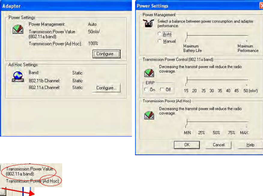
Setting Transmit Power Using the Intel PROSet Configuration Utility
1. Start Intel PROSet. In the PROSet interface, click the Adapter tab.
2. In the Power Settings section of the Adapter screen, click Configure.
3. On the Power Settings window, find the Transmission Power Control (802.11a band)
section.
The default setting under EIRP is ON. This setting is not modifiable by the
user.
The default transmission power setting on the slider is 50 milliwatts (mW).
These default settings allow use of the Intel adapter in countries where
802.11a is currently allowed, including Australia, Austria, Belgium, Canada,
Czech Republic, Denmark, Finland, France, Germany, Hong Kong,
Hungary, Iceland, Ireland, Italy, Luxembourg, Malta, Mexico, Netherlands,
New Zealand, Norway, Poland, Portugal, Saudi Arabia, Singapore, South
Africa, Switzerland, Turkey, United Kingdom, USA.
4. To reduce the amount of output power used, move the power slider bar to a
lower value, then check the strength and quality of the wireless link, using
the Intel PROSet icon in the system tray or the General tab in Intel PROSet.
5. Modify the power setting repeatedly until you find the lowest power setting
value that still yields acceptable link quality.
Additional 802.11a and 802.11b Restrictions
All EU countries
Use of 802.11a is indoors only.
France
Note: At the time of publication of this document, operation of Intel® PRO/Wireless 2100A LAN
MiniPCI Adapters in 802.11b mode was restricted in France to indoor use only and was allowable in
only 58 specific regional “départements” due to local restrictions on transmission power and
frequencies. The departments in which the Intel adapter can currently be used are listed below.
Since it is likely that additional permitted departments will be added to the list at regular intervals,
visit the website of the French Authority for Regulation of Telecommunications (ART) for updated
information, in French at http://www.art-telecom.fr/ or in English at
http//www.art-telecom.fr/eng/
Departments in Which the Intel Wireless LAN MiniPCI Adapter Can Be Used (Indoors Only)
The Intel® PRO/Wireless 2100A LAN MiniPCI Adapter can currently be used in the following
departments of mainland France, and in those departments, indoors only.
01 Ain 36 Indre 69 Rhône
02 Aisne 37 Indre et Loire 70 Haute Saône
03 Allier 39 Jura 71 Saône et Loire
05 Hautes Alpes 41 Loir et Cher 72 Sarthe
08 Ardennes 42 Loire 75 Paris
09 Ariège 45 Loiret 77 Seine et Marne
10 Aube 50 Manche 78 Yvelines
11 Aude 54 Meurthe et Moselle 79 Deux Sèvres
12 Aveyron 55 Meuse 82 Tarn et Garonne
16 Charente 57 Moselle 84 Vaucluse
19 Corrèze 58 Nièvre 86 Vienne
2A Corse Sud 59 Nord 88 Vosges
2B Haute Corse 60 Oise 89 Yonne
21 Côte d’Or 61 Orne 90 Territoire de Belfort
24 Dordogne 63 Puy du Dôme 91 Essonne
25 Doubs 64 Pyrénées Atlantique 92 Hauts de Seine
26 Drôme 65 Haute Pyrénées 93 Seine St Denis
27 Eure 66 Pyrénées Orientales 94 Val de Marne
32 Gers 67 Bas Rhin
35 Ille et Vilaine 68 Haut Rhin
Departments in Which the Intel Wireless LAN MiniPCI Adapter Cannot Be
Used
The Intel® PRO/Wireless 2100A LAN MiniPCI Adapter cannot currently be used in
any departments of mainland France other than those listed above. Before
operating your computer device or system in a department not listed above, see
the heading in this section “How to Turn Off the Wireless LAN Radio.”
Maximum allowable EIRP 802.11b wireless LAN cards in the mainland
departments of France not shown in the table above are as follows: (See the ART
website at www.art-telecom.fr for information on the French overseas territories.)
Frequency Ranges
(MHz) Indoors Outdoors
2400 – 2446.5 10 mW Not permitted
2446.5 – 2483.5 100 mW 100 mW on private property with Ministry of Defense
approval
How to turn off the wireless LAN radio
Note: Turning the wireless LAN radio off is not the same as disabling the wireless LAN card. It is
not necessary to disable the card to meet the regulatory requirements.
While operating the computer or system incorporating the Intel® PRO/Wireless 2100A LAN
MiniPCI in those French departments that do not allow use of the wireless LAN equipment, the user
of the equipment must turn off the wireless LAN radio in order to comply with local regulations.
Instructions on how to do this are provided below.
How to turn off the WLAN radio using software
If Intel® PROSet is installed
To turn off the wireless LAN radio using Intel PROSet:
1. Right-click the Intel(R) PRO/Wireless card icon in the system tray
2. Select the active Intel adapter and click Switch Radio Off.
3. You can also turn off the radio on the General tab of the Intel PROSet screen, by selecting
Off next to Switch radio.
If Intel PROSet is not installed
To turn off the wireless LAN radio using the Control Panel:
1. Access the Control Panel and double-click the System icon.
2. Go to Device Manager under Hardware and expand the list of Network Adapters.
3. Double-click the Intel PRO/Wireless MiniPCI LAN Adapter and select the Advanced tab.
4. On the Advanced tab, check the Wireless device off (radio off) check box, and click OK.
Japan
Indoor use only.
Taiwan
第十四條 經型式認證合格之低功率射頻電機,非經許可,公司、商號或使用者均不得擅自變更頻
率、加大功率或變更原計之特性及功能。
第十七條 低功率射頻電機之使用不得影響飛航安全及干擾合法通信;經發現有干擾現象時,應立
即停用,並改善至無干擾時方得繼續使用。
前項合法通信,指依電信法規定作業之無線電信。
低功率射頻電機須忍受合法通信或工業、科學及醫療用電波輻射電機設備之干擾。
United States
USA and Canada Safety Requirements and Notices
The FCC with its action in ET Docket 93-62 has adopted a safety standard for human exposure to
radio frequency (RF) electromagnetic energy emitted by FCC certified equipment. The Intel
PRO/Wireless LAN MiniPCI Adapter products meet the Human Exposure limits found in OET
Bulletin 65, 2001, and ANSI/IEEE C95.1, 1992. Proper operation of this radio according to the
instructions found in this manual will result in exposure substantially below the FCC’s
recommended limits.
The following safety precautions should be observed:
• Do not touch or move antenna while the unit is transmitting or receiving.
• Do not hold any component containing the radio such that the antenna is very close or
touching any exposed parts of the body, especially the face or eyes, while transmitting.
• Do not operate the radio or attempt to transmit data unless the antenna is connected; if not,
the radio may be damaged.
Use in specific environments:
The use of wireless devices in hazardous locations is limited by the constraints posed by the safety
directors of such environments.
The use of wireless devices on airplanes is governed by the Federal Aviation Administration (FAA).
The use of wireless devices in hospitals is restricted to the limits set forth by each hospital.
Antenna use:
Note: Any U-NII device that operates in the 5.15-5.25 GHz band shall use a transmitting antenna
that is an integral part of the device.
In order to comply with FCC RF exposure limits, low gain integrated antennas should be located at
a minimum distance of 2 cm or more from the body of all persons.
High-gain, wall-mount, or mast-mount antennas are designed to be professionally installed and
should be located at a minimum distance of 3 cm or more from the body of all persons. Please
contact your professional installer, VAR, or antenna manufacturer for proper installation
requirements.
Explosive Device Proximity Warning
Warning: Do not operate a portable transmitter (such as a wireless network device) near
unshielded blasting caps or in an explosive environment unless the device has been modified to be
qualified for such use.
Antenna Warning
Warning: To comply with the FCC and ANSI C95.1 RF exposure limits, it is recommended for Intel
PRO/Wireless 2100A LAN MiniPCI Adapters installed in a desktop or portable computer, that the
antenna for this device be installed so as to provide a separation distance of al least 2 cm from all
persons and that the antenna must not be co-located or operating in conjunction with any other
antenna or radio transmitter. It is recommended that the user limit exposure time if the antenna is
positioned closer than 2 cm.
Use On Aircraft Caution
Caution: Regulations of the FCC and FAA prohibit airborne operation of radio-frequency wireless
devices because their signals could interfere with critical aircraft instruments.
Other Wireless Devices
Safety Notices for Other Devices in the Wireless Network: Refer to the documentation supplied
with wireless Ethernet adapters or other devices in the wireless network.
USA Radio Frequency Interference Requirements
This device is restricted to indoor use when used over its full frequency bandwidth capabilities (5.15
to 5.35 GHz) due to its operation in the 5.15 to 5.25 GHz frequency range. FCC requires this
product to be used indoors for the frequency range 5.15 to 5.25 GHz to reduce the potential for
harmful interference to co-channel Mobile Satellite systems. The product can be used outdoors
only if the frequency range is limited to 5.26 to 5.35 GHz. In addition, it should be noted that high
power radars are allocated as primary users of the 5.25 to 5.35 GHz and 5.65 to 5.85 GHz bands.
These radar stations can cause interference with and /or damage this device. See the user’s guide
for information on specifying the radio frequency to be used.
FCC Regulations Part 15 Declaration of Conformity (DoC)
Intel Corporation declares that the equipment described in this document is within the requirements
of the Code of Federal Regulations listed below:
Title 47 Part 15, Subpart B, Class B for a digital device.
This declaration is based upon the compliance of the Intel(R) PRO/Wireless LAN MiniPCI Adapters
to the above standards. Intel has determined that the models listed have been shown to comply
with the applicable technical standards if no unauthorized change is made in the equipment and if
the equipment is properly maintained and operated.
These units are identical to the units tested and found acceptable with the applicable standards.
Records maintained by Intel continue to reflect that units being produced under this Declaration of
Conformity, within the variation that can be expected due to quantity production and tested on a
statistical basis, continue to comply with the applicable technical standards.
FCC Rules and Regulations - Part 15
This device uses, generates and radiates radio frequency energy. The radio frequency energy
produced by this device is well below the maximum exposure allowed by the Federal
Communications Commission (FCC).
• This device complies with the limits for a Class B digital device pursuant to Part 15 subpart C
of the FCC Rules and Regulations. Operation is subject to the following two conditions:
• This device may not cause harmful interference.
• This device must accept any interference received, including interference that may cause
undesired operation.
The FCC limits are designed to provide reasonable protection against harmful interference when
the equipment is installed and used in accordance with the instruction manual and operated in a
commercial environment. However, there is no guarantee that interference will not occur in a
particular commercial installation, or if operated in a residential area.
If harmful interference with radio or television reception occurs when the device is turned on, the
user must correct the situation at the user’s own expense. The user is encouraged to try one or
more of the following corrective measures:
• Re-orient or relocate the receiving antenna.
• Increase the separation between the equipment and receiver.
• Connect the equipment into an outlet on a circuit different from that on which the receiver is
connected.
• Consult the dealer or an experienced radio/TV technician for help.
CAUTION: The Part 15 radio device operates on a non-interference basis with other devices
operating at this frequency. Any changes or modification to said product not expressly approved by
Intel could void the user's authority to operate this device.