Woods Equipment Ditch Bank S105 3 Users Manual / S106 Rotary Cutter
S106-3 to the manual 4ca7c13a-08d3-490a-baee-e8d64e339d75
2015-02-05
: Woods-Equipment Woods-Equipment-Ditch-Bank-S105-3-Users-Manual-408477 woods-equipment-ditch-bank-s105-3-users-manual-408477 woods-equipment pdf
Open the PDF directly: View PDF ![]() .
.
Page Count: 58

OPER ATOR'S MANUAL
DITCH BANK
ROTARY CUTTER
29977
(Rev. 1/23/2009)
S105-3
S106-3
S105Q-3
S106Q-3

2 Introduction
Gen’l (Rev. 2/19/2008)
TO THE DEALER:
Assembly and proper installation of this product is the responsibility of the Woods® dealer. Read manual instructions
and safety rules. Make sure all items on the Dealer’s Pre-Delivery and Delivery Check Lists in the Operator’s Manual
are completed before releasing equipment to the owner.
The dealer must complete the Product Registration online at the Woods Dealer Website or complete the mail-in
form included with the Operator’s Manual. If using the mail-in form, the dealer is to return the prepaid postage portion to
Woods, give one copy to the customer, and retain one copy. Failure to register the product does not diminish
customer’s warranty rights.
TO THE OWNER:
Read this manual before operating your Woods equipment. The information presented will prepare you to do a better and
safer job. Keep this manual handy for ready reference. Require all operators to read this manual carefully and become
acquainted with all adjustment and operating procedures before attempting to operate. Replacement manuals can be
obtained from your dealer. To locate your nearest dealer, check the Dealer Locator at www.WoodsEquipment.com, or in
the United States and Canada call 1-800-319-6637.
The equipment you have purchased has been carefully engineered and manufactured to provide dependable and
satisfactory use. Like all mechanical products, it will require cleaning and upkeep. Lubricate the unit as specified.
Observe all safety information in this manual and safety decals on the equipment.
For service, your authorized Woods dealer has trained mechanics, genuine Woods service parts, and the necessary
tools and equipment to handle all your needs.
Use only genuine Woods service parts. Substitute parts will void the warranty and may not meet standards required for
safe and satisfactory operation. Record the model number and serial number of your equipment in the spaces
provided:
Model: _______________________________ Date of Purchase: _____________________
Serial Number: (see Safety Decal section for location) ____________________________________
Provide this information to your dealer to obtain correct repair parts.
Throughout this manual, the term NOTICE is used to indicate that failure to observe can cause damage to equipment.
The terms CAUTION, WARNING, and DANGER are used in conjunction with the Safety-Alert Symbol (a triangle with
an exclamation mark) to indicate the degree of hazard for items of personal safety.

Introduction 3
29977 (Rev. 1/23/2009)
TABLE OF CONTENTS
INTRODUCTION . . . . . . . . . . . . . . . . . . . . . . . . . . . . . . . . . . . . . . . . . . . . . . 2
SPECIFICATIONS. . . . . . . . . . . . . . . . . . . . . . . . . . . . . . . . . . . . . . . . . . . . . 4
GENERAL INFORMATION . . . . . . . . . . . . . . . . . . . . . . . . . . . . . . . . . . . . . 4
SAFETY VIDEO ORDER FORM . . . . . . . . . . . . . . . . . . . . . . . . . . . . . . . . . . 5
SAFETY RULES . . . . . . . . . . . . . . . . . . . . . . . . . . . . . . . . . . . . . . . . . . . . . . 7
SAFETY DECALS . . . . . . . . . . . . . . . . . . . . . . . . . . . . . . . . . . . . . . . . . . . . 10
OPERATION . . . . . . . . . . . . . . . . . . . . . . . . . . . . . . . . . . . . . . . . . . . . . . . . 13
OWNER SERVICE . . . . . . . . . . . . . . . . . . . . . . . . . . . . . . . . . . . . . . . . . . . 17
TROUBLESHOOTING. . . . . . . . . . . . . . . . . . . . . . . . . . . . . . . . . . . . . . . . . 20
DEALER SERVICE . . . . . . . . . . . . . . . . . . . . . . . . . . . . . . . . . . . . . . . . . . . 21
DEALER CHECK LISTS . . . . . . . . . . . . . . . . . . . . . . . . . . . . . . . . . . . . . . . 28
ASSEMBLY . . . . . . . . . . . . . . . . . . . . . . . . . . . . . . . . . . . . . . . . . . . . . . . . . 29
PARTS INDEX. . . . . . . . . . . . . . . . . . . . . . . . . . . . . . . . . . . . . . . . . . . . . . . 35
BOLT TORQUE CHART . . . . . . . . . . . . . . . . . . . . . . . . . . . . . . . . . . . . . . . 54
BOLT SIZE CHART AND ABBREVIATIONS . . . . . . . . . . . . . . . . . . . . . . . 55
INDEX . . . . . . . . . . . . . . . . . . . . . . . . . . . . . . . . . . . . . . . . . . . . . . . . . . . . . 56
PRODUCT WARRANTY . . . . . . . . . . . . . . . . . . . . . . . . . . . . . . . . . . . . . . . 57
REPLACEMENT PARTS WARRANTY . . . . . . . . . . . . . . . . . . .BACK COVER

4 Introduction
29977 (Rev. 11/23/2009)
SPECIFICATIONS
GENERAL INFORMATION
Some illustrations in this manual show the cut-
ter with safety shields removed to provide a better
view. The cutter should never be operated with any
safety shielding removed.
The purpose of this manual is to assist you in operating
and maintaining your cutter. Read it carefully. It fur-
nishes information and instructions that will help you
achieve years of dependable performance. These
instructions have been compiled from extensive field
experience and engineering data. Some information
may be general in nature due to unknown and varying
operating conditions. However, through experience
and these instructions, you should be able to develop
procedures suitable to your particular situation.
The illustrations and data used in this manual were cur-
rent at the time of printing, but due to possible inline
production changes, your machine may vary slightly in
detail. We reserve the right to redesign and change the
machines as may be necessary without notification.
Throughout this manual, references are made to right
and left directions. These are determined by standing
behind the equipment facing the direction of forward
travel. Blade rotation is clockwise as viewed from the
top of the cutter.
S105 S105Q S106 S106Q
Cutting Width 60" 60" 72" 72"
PTO Speed (rpm) 540 1000 540 1000
Blade Tip Speed (feet per minute) 11,451 14,137 10,178 12,566
Minimum Tractor Weight Recommended 4000 lbs 4000 lbs 5000 lbs 5000 lbs
Minimum Tractor HP Recommended 40 HP 40 HP 50 HP 50 HP
Minimum 3-Point Lift Capacity 2500 lbs 2500 lbs 3000 lbs 3000 lbs
Cutting Height (Depending on 3-point hitch height) . . . . . . . . . . . . . . . . . . . . . . . . . . . . . . . . . . . . . . 1-1/2" - 12"
3-Point Hitch (Category 1 pins are available) . . . . . . . . . . . . . . . . . . . . . . . . . . . . . . . . . . . . . . . . . . Category 2
Offset from Centerline Tractor PTO to Inside Edge of Cut (Approximate) . . . . . . . . . . . . . . . . . . . . . . . . . . . 63"
Transport Width from Centerline PTO to Right Side with Head Raised (Approximate) . . . . . . . . . . . . . . . . . 70"
WARNING

Safety 5
Safety Video Order Form (8/2/2005)
Free Mower Safety Video
Fill out and return the order form and we will send you a FREE VHS
or DVD video outlining
Industrial and Agricultural Mower Safety
Practices
. The 22 minute video, developed in cooperation with
AEM (Association of Equipment Manufacturers), reinforces the
proper procedures to follow while operating your mowing
equipment. The video does not replace the information contained in
the Operator’s Manual, so please review this manual thoroughly
before operating your new mowing equipment.
Safety Training
Does Make a Difference.
BE SAFE!
BE ALERT!
BE ALIVE!
BE TRAINED
Before Operating Mowers!
ASSOCIATION OF
EQUIPMENT
MANUFACTURERS
Safety Video Order Form

6 Safety
Safety Video Order Form (Rev. 2/6/2006)
Free Mower/Cutter Safety Video Order Form
3 (Select one)
VHS Format - VHS01052 Safety Video
DVD Format - DVD01052 Safety Video
Please send me
Name: ________________________________________ Phone: __________________
Address: _____________________________________
_____________________________________
_____________________________________
Mower/Cutter Model: ______________________ Serial #: ________________________
Send to: ATTENTION: DEALER SERVICES
WOODS EQUIPMENT COMPANY
PO BOX 1000
OREGON IL 61061-1000
Also, available from the Association of Equipment Manufacturers:
A large variety of training materials (ideal for groups) are available for a nominal
charge from AEM. Following is a partial list:
●Training Package for Rotary Mowers/Cutters-English
Contains: DVD & VHS (English)
Guidebook for Rotary Mowers/Cutters (English)
AEM Industrial/Agricultural Mower Safety Manual (English)
AEM Agricultural Tractor Safety Manual (English)
●Training Package for Rotary Mowers/Cutters-English/Spanish
Contains: DVD & VHS (English/Spanish)
Guidebook for Rotary Mowers/Cutters (English/Spanish)
AEM Industrial/Agricultural Mower Safety Manual (English/Spanish)
AEM Agricultural Tractor Safety Manual (English/Spanish)
AEM training packages are available through:
AEM at:
www.aem.org
or
Universal Lithographers, Inc.
Email: aem@ulilitho.com
800-369-2310 tel
866-541-1668 fax

Safety 7
S/HS 105/106 Safety Rules (Rev. 7/7/2006)
INSTALLATION
Hydraulics must be connected as instructed in
this manual. Do not substitute parts, modify, or
connect in any other way.
TRAINING
Safety instructions are important! Read all
attachment and power unit manuals; follow all
safety rules and safety decal information. (Replace-
ment manuals and safety decals are available from
your dealer. To locate your nearest dealer, check
the Dealer Locator at www.WoodsEquipment.com,
or in the United States and Canada call 1-800-319-
6637.) Failure to follow instructions or safety rules
can result in serious injury or death.
If you do not understand any part of this manual
and need assistance, see your dealer.
Know your controls and how to stop engine and
attachment quickly in an emergency.
Operators must be instructed in and be capable
of the safe operation of the equipment, its attach-
ments, and all controls. Do not allow anyone to
operate this equipment without proper instructions.
Keep hands and body away from pressurized
lines. Use paper or cardboard, not hands or other
body parts to check for leaks. Wear safety goggles.
Hydraulic fluid under pressure can easily penetrate
skin and will cause serious injury or death.
Make sure that all operating and service person-
nel know that if hydraulic fluid penetrates skin, it
must be surgically removed as soon as possible by
a doctor familiar with this form of injury or gan-
grene, serious injury, or death will result. CON-
TACT A PHYSICIAN IMMEDIATELY IF FLUID
ENTERS SKIN OR EYES. DO NOT DELAY.
Never allow children or untrained persons to
operate equipment.
PREPARATION
Check that all hardware is properly installed.
Always tighten to torque chart specifications
unless instructed otherwise in this manual.
Air in hydraulic systems can cause erratic oper-
ation and allows loads or equipment components
to drop unexpectedly. When connecting equipment
or hoses or performing any hydraulic maintenance,
purge any air in hydraulic system by operating all
hydraulic functions several times. Do this before
putting into service or allowing anyone to
approach the equipment.
Make sure all hydraulic hoses, fittings, and
valves are in good condition and not leaking before
starting power unit or using equipment. Check and
route hoses carefully to prevent damage. Hoses
must not be twisted, bent sharply, kinked, frayed,
pinched, or come into contact with any moving
parts. Operate moveable components through full
operational range to check clearances. Replace
any damaged hoses immediately.
After connecting hoses, check that all control
lever positions function as instructed in the Opera-
tor's Manual. Do not put into service until control
lever and equipment movements are correct.
Set tractor hydraulic relief valve at 2500 psi (170
bars) (17,000 kPa) to prevent injury and equipment
damage due to hydraulic system failure.
Your dealer can supply original equipment
hydraulic accessories and repair parts. Substitute
parts may not meet original equipment specifica-
tions and may be dangerous.
Always wear relatively tight and belted clothing
to avoid getting caught in moving parts. Wear
sturdy, rough-soled work shoes and protective
equipment for eyes, hair, hands, hearing, and head;
and respirator or filter mask where appropriate.
Make sure spring-activated locking pin or collar
slides freely and is seated firmly in tractor PTO
spline groove.
Make sure attachment is properly secured,
adjusted, and in good operating condition.
(Safety Rules continued on next page)
Safety is a primary concern in the design and
manufacture of our products. Unfortunately, our
efforts to provide safe equipment can be wiped
out by an operator’s single careless act.
In addition to the design and configuration of
equipment, hazard control and accident preven-
tion are dependent upon the awareness, con-
cern, judgement, and proper training of
personnel involved in the operation, transport,
maintenance, and storage of equipment.
It has been said, “The best safety device is an
informed, careful operator.” We ask you to be
that kind of operator.
SAFETY RULES
ATTENTION! BECOME ALERT! YOUR SAFETY IS INVOLVED!

8 Safety
S/HS 105/106 Safety Rules (Rev. 7/7/2006)
(Safety Rules continued from previous page)
Power unit must be equipped with ROPS or
ROPS cab and seat belt. Keep seat belt securely
fastened. Falling off power unit can result in death
from being run over or crushed. Keep foldable
ROPS system in “locked up” position at all times.
Remove accumulated debris from this equip-
ment, power unit, and engine to avoid fire hazard.
Make sure all safety decals are installed.
Replace if damaged. (See Safety Decals section for
location.)
Make sure shields and guards are properly
installed and in good condition. Replace if dam-
aged.
You must use a center frame counterweight box
filled with steel to a minimum 400 lbs.
Do not put this equipment into service unless all
side skids are properly installed and in good condi-
tion. Replace if damaged.
A minimum 20% of tractor and equipment
weight must be on the tractor front wheels when
attachments are in transport position. Without this
weight, tractor could tip over, causing personal
injury or death. The weight may be attained with a
loader, front wheel weights, ballast in tires or front
tractor weights. Weigh the tractor and equipment.
Do not estimate.
Inspect and clear area of stones, branches, or
other hard objects that might be thrown, causing
injury or damage.
TRANSPORTATION
Power unit must be equipped with ROPS or
ROPS cab and seat belt. Keep seat belt securely
fastened. Falling off power unit can result in death
from being run over or crushed. Keep foldable
ROPS system in “locked up” position at all times.
Before transporting, stop tractor PTO, raise cut-
ter center section, then raise cutter head, and
install transport bar. A raised cutter head can fall
and crush. Keep away; never go underneath. Lower
cutter head after transport and for storage.
Always comply with all state and local lighting
and marking requirements.
Never allow riders on power unit or attachment.
Do not operate PTO during transport.
Do not operate or transport on steep slopes.
Do not operate or transport equipment while
under the influence of alcohol or drugs.
Use additional caution and reduce speed when
under adverse surface conditions, turning, or on
inclines.
OPERATION
Do not allow bystanders in the area when oper-
ating, attaching, removing, assembling, or servic-
ing equipment.
Never walk, stand, or place yourself or others
under a raised wing or in the path of a lowering
wing. Hydraulic system leak-down, hydraulic sys-
tem failures, mechanical failures, or movement of
control levers can cause wings to drop unexpect-
edly and cause severe injury or death.
Full chain shielding must be installed when
operating in populated areas or other areas where
thrown objects could injure people or damage
property.
• If this machine is not equipped with full chain
shielding, operation must be stopped when any-
one comes within 300 feet (92 m).
• This shielding is designed to reduce the risk
of thrown objects. The mower deck and protec-
tive devices cannot prevent all objects from
escaping the blade enclosure in every mowing
condition.
It is possible for objects to ricochet
and escape, traveling as much as 300 feet (92 m).
Never direct discharge toward people, animals,
or property.
Do not operate or transport equipment while
under the influence of alcohol or drugs.
Operate only in daylight or good artificial light.
Keep hands, feet, hair, and clothing away from
equipment while engine is running. Stay clear of all
moving parts.
Never allow riders on power unit or attachment.
Power unit must be equipped with ROPS or
ROPS cab and seat belt. Keep seat belt securely
fastened. Falling off power unit can result in death
from being run over or crushed. Keep foldable
ROPS system in “locked up” position at all times.
Always sit in power unit seat when operating
controls or starting engine. Securely fasten seat
belt, place transmission in neutral, engage brake,
and ensure all other controls are disengaged
before starting power unit engine.
SAFETY RULES
ATTENTION! BECOME ALERT! YOUR SAFETY IS INVOLVED!
(Rev. 1/23/2009)

Safety 9
S/HS 105/106 Safety Rules (Rev. 7/7/2006)
Operate tractor PTO at 540 RPM (1000 RPM on Q
Series cutters). Do not exceed.
Raise or lower wings slowly to prevent personal
injury or damage to cutter.
Look down and to the rear and make sure area
is clear before operating in reverse.
Do not operate or transport on steep slopes.
Do not stop, start, or change directions sud-
denly on slopes.
Watch for hidden hazards on the terrain during
operation.
Stop power unit and equipment immediately
upon striking an obstruction. Turn off engine,
remove key, inspect, and repair any damage before
resuming operation.
MAINTENANCE
Before dismounting power unit or performing
any service or maintenance, follow these steps:
disengage power to equipment, lower the 3-point
hitch and all raised components to the ground,
operate valve levers to release any hydraulic pres-
sure, set parking brake, stop engine, remove key,
and unfasten seat belt.
Before performing any service or maintenance,
lower attachment to ground, turn off engine, set
parking brake, and remove key.
Do not modify or alter or permit anyone else to
modify or alter the equipment or any of its compo-
nents in any way.
Your dealer can supply original equipment
hydraulic accessories and repair parts. Substitute
parts may not meet original equipment specifica-
tions and may be dangerous.
To prevent contamination, clean and then cover
hose ends, fittings, and hydraulic ports with tape.
Do not allow bystanders in the area when oper-
ating, attaching, removing, assembling, or servic-
ing equipment.
Never go underneath equipment (lowered to the
ground or raised) unless it is properly blocked and
secured. Never place any part of the body under-
neath equipment or between moveable parts even
when the engine has been turned off. Hydraulic
system leak down, hydraulic system failures,
mechanical failures, or movement of control levers
can cause equipment to drop or rotate unexpect-
edly and cause severe injury or death. Follow Oper-
ator's Manual instructions for working underneath
and blocking requirements or have work done by a
qualified dealer.
Make sure attachment is properly secured,
adjusted, and in good operating condition.
Keep all persons away from operator control
area while performing adjustments, service, or
maintenance.
Make certain all movement of equipment com-
ponents has stopped before approaching for ser-
vice.
Frequently check blades. They should be sharp,
free of nicks and cracks, and securely fastened.
Do not handle blades with bare hands. Careless
or improper handling may result in serious injury.
Your dealer can supply genuine replacement
blades. Substitute blades may not meet original
equipment specifications and may be dangerous.
Tighten all bolts, nuts, and screws to torque
chart specifications. Check that all cotter pins are
installed securely to ensure equipment is in a safe
condition before putting unit into service.
Make sure all safety decals are installed.
Replace if damaged. (See Safety Decals section for
location.)
Make sure shields and guards are properly
installed and in good condition. Replace if dam-
aged.
Never perform service or maintenance with
engine running.
Do not disconnect hydraulic lines until machine
is securely blocked or placed in lowest position
and system pressure is released by operating
valve levers.
Service and maintenance work not covered in
OWNER SERVICE must be done by a qualified
dealership. Special skills, tools, and safety proce-
dures may be required. Failure to follow these
instructions can result in serious injury or death.
STORAGE
Keep children and bystanders away from stor-
age area.
Store on level, solid ground.
Block equipment securely for storage.
SAFETY RULES
ATTENTION! BECOME ALERT! YOUR SAFETY IS INVOLVED!
(Rev. 1/23/2009)
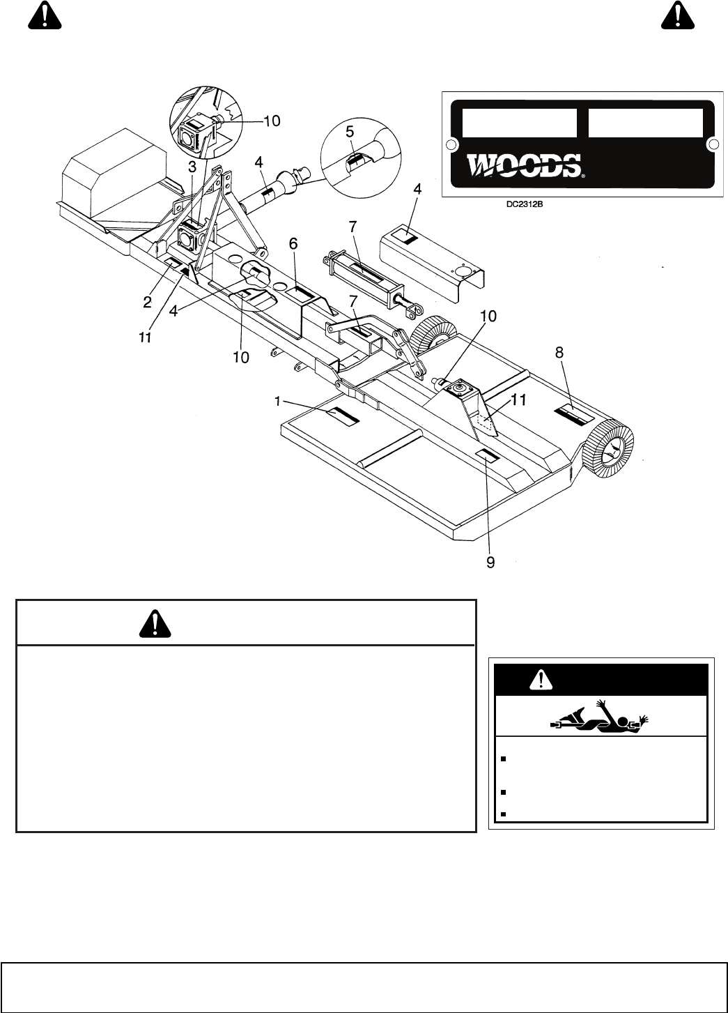
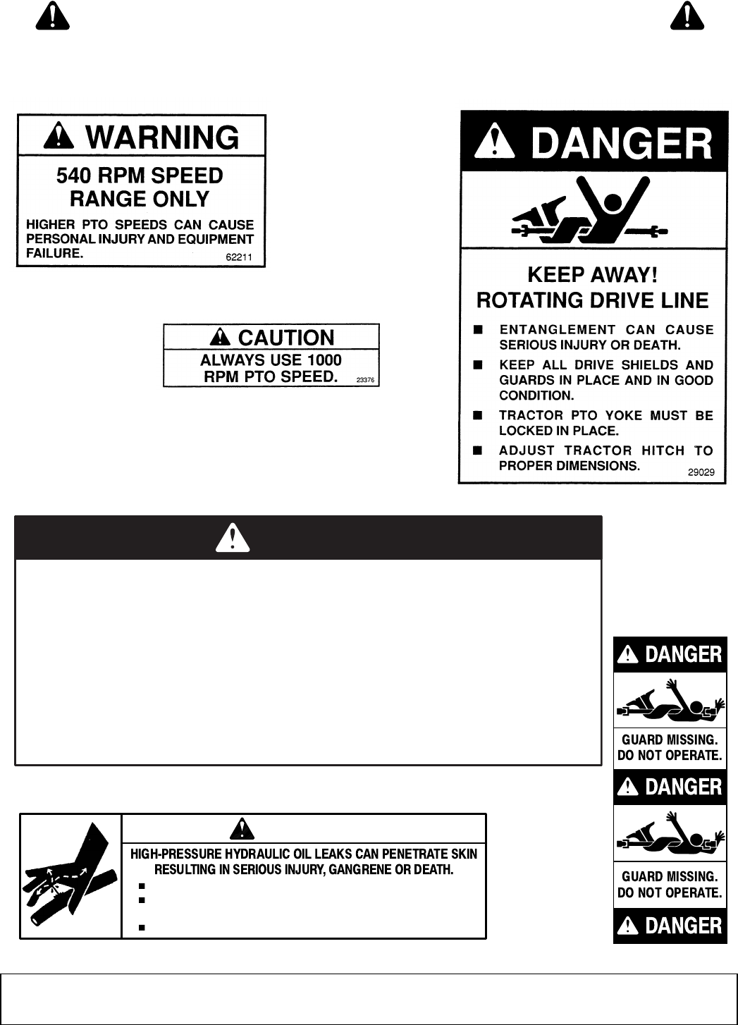
10 Safety
29977 (Rev. 1/20/2006)
TO AVOID SERIOUS INJURY OR DEATH,
Read Operator’s Manual and follow all safety, operating, and service
instructions. (Contact dealer for manuals.)
Keep all guards and shields in place and in good condition.
Lower implement, shut off, and remove key before leaving or servicing.
Block up equipment and remove key before working underneath.
Never allow children or unqualified persons to operate.
Clear mowing area of all debris.
Be careful on uneven terrain. Reduce speed when turning. 32005-E
WARNING
1 - PN 32005
DANGER
ENTANGLEMENT WITH ROTATING DRIVE
PARTS OR FALLING OFF CAN CAUSE
INJURY OR DEATH.
KEEP ALL DRIVE SHIELDS AND GUARDS
IN PLACE AND IN GOOD CONDITION.
ALLOW NO RIDERS. 25023-H
KEEP AWAY!
2 - PN 25023
11 - SERIAL NUMBER PLATE
MODEL NO. SERIAL NO.
Woods Equipment Company
Oregon, Illinois, U.S.A.
SAFETY & INSTRUCTIONAL DECALS
ATTENTION! BECOME ALERT! YOUR SAFETY IS INVOLVED!
Replace Immediately If Damaged!
(Safety Decals continued on next page)
Safety 11
29977 (Rev. 1/20/2006)
33347E
5 - PN 33347
,HTAEDROYRUJNISUOIRESDIOVAOT
HHerutcurtsevitcetorprevo-lloresU.tnempiuqesihthtiwstlebtaesdna
H.tespurotcartdiovaotthgiewdnaezistneici
ffusfosrotcartnoylnor
ew
o
msihtesU
H.nrutrevodluocrotcartsa,edisllihnwodnorewomhtiwknabpeetsnoro
tcarteta
r
eporeveN
Hedisrosni-evac,stuo-hsawdiovaotsknabpe
e
tsgnola
g
niwomneh
w
noitua
ce
m
e
r
t
x
ee
sU
.tnemknabmefforotc
artllupdluochcihwtfard
Hrewom
d
naerusolcneevitcetorprob
a
cesU wolebsknabgniwomnehwgnidleihsniahc
.st
c
ejbon
worhtmorfrotar
e
potcetorpotleveled
ar
g
H.t
rops
na
rtro
fn
ia
hc
dnar
ab
pu
-kc
ol
h
ctals
y
aw
lA
H.noitisop
d
esiarnitinu
htiwde
d
ne
t
tanur
o
tc
a
rtevael
r
eveN
G-
72582
DANGER
6 - PN 28527
Check for leaks with cardboard; never use hand.
Before loosening fittings: lower load, release pressure, and
be sure oil is cool.
Consult physician immediately if skin penetration occurs.
WARNING
19924-B
7 - PN 19924
3 - PN 62211
3 - PN 23376
-or-
4 - PN 29029
SAFETY & INSTRUCTIONAL DECALS
ATTENTION! BECOME ALERT! YOUR SAFETY IS INVOLVED!
Replace Immediately If Damaged!
(Safety Decals continued from previous page)

12 Safety
29977 (Rev. 1/20/2006)
SAFETY & INSTRUCTIONAL DECALS
ATTENTION! BECOME ALERT! YOUR SAFETY IS INVOLVED!
Replace Immediately If Damaged!
BE CAREFUL!
Use a clean, damp cloth to clean safety decals.
Avoid spraying too close to decals when using a pressure
washer; high-pressure water can enter through very small
scratches or under edges of decals causing them to peel or
come off.
Replacement safety decals can be ordered free from your
Woods dealer. To locate your nearest dealer, check the Dealer
Locator at www.WoodsEquipment.com, or in the United States
and Canada call 1-800-319-6637.
8 - PN 32241
9 - PN 26483
Operation 13
29977 (Rev. 1/23/2009)
OPERATION
The operator is responsible for the safe operation of
the cutter. The operator must be properly trained.
Operators should be familiar with the cutter, the tractor,
and all safety practices before starting operation. Read
the safety rules and safety decals on page 7 through
page 12.
This machine is a heavy-duty cutter designed for ditch-
bank and side bank mowing. Five foot and six foot cut-
ting heads are available in 540 rpm and 1000 rpm mod-
els.
The 1000 rpm unit is designated with the marking
“1000 rpm” on the front and rear center frame, and the
input gearbox has a “1000 rpm” tag attached to it.
Full chain shielding must be installed when
operating in populated areas or other areas where
thrown objects could injure people or damage
property.
• If this machine is not equipped with full chain
shielding, operation must be stopped when any-
one comes within 300 feet (92 m).
• This shielding is designed to reduce the risk
of thrown objects. The mower deck and protec-
tive devices cannot prevent all objects from
escaping the blade enclosure in every mowing
condition.
It is possible for objects to ricochet
and escape, traveling as much as 300 feet (92 m).
Never allow children or untrained persons to
operate equipment.
Keep bystanders away from equipment.
Never allow riders on power unit or attachment.
Keep all persons away from operator control
area while performing adjustments, service, or
maintenance.
Stop power unit and equipment immediately
upon striking an obstruction. Turn off engine,
remove key, inspect, and repair any damage before
resuming operation.
Always wear relatively tight and belted clothing
to avoid getting caught in moving parts. Wear
sturdy, rough-soled work shoes and protective
equipment for eyes, hair, hands, hearing, and head;
and respirator or filter mask where appropriate.
Operate tractor PTO at 540 RPM (1000 RPM on Q
Series cutters). Do not exceed.
GENERAL TRACTOR REQUIREMENTS
Mount on tractors of adequate size; 4000 lbs minimum
weight for S105, and 5000 lbs minimum weight for
S106. Tractors should have a minimum 3-point lift
capacity of 2500 lbs for the S105 and 3000 lbs for the
S106.
Stabilizer bars must be used on lower 3-point hitch
arms to minimize cutter side to side sway.
An adjustable, rigid top link must be used to achieve
the tilt adjustments.
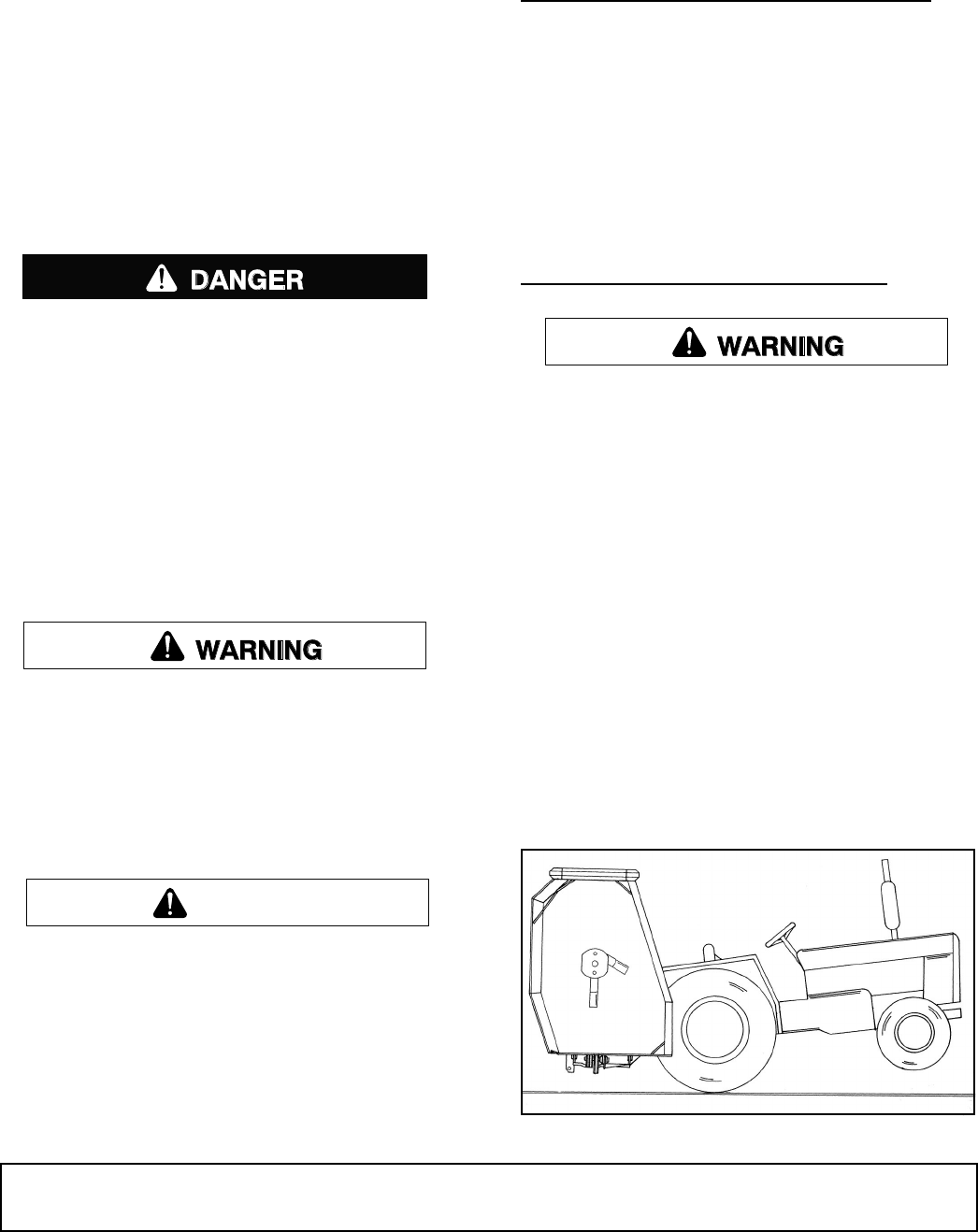
TRACTOR FRONT END STABILITY
A minimum 20% of tractor and equipment
weight must be on the tractor front wheels when
attachments are in transport position. Without this
weight, tractor could tip over, causing personal
injury or death. The weight may be attained with a
loader, front wheel weights, ballast in tires or front
tractor weights. Weigh the tractor and equipment.
Do not estimate.
You must use a center frame counterweight box
filled with steel to a minimum 400 lbs.
The use of 3-point mounted equipment can cause loss
of tractor front end stability.
If there is any question at all of the tractor stability or
the tractor rockshaft strength, use a counterweight of
approximately 400 lbs or more on left end of cutter cen-
ter frame. The rockshaft is required to carry all torsion
load resulting from cutter head weight. Adding weight
to the left side of the cutter frame reduces the torsion
load.
Figure 1. Tractor Stability
CAUTION
DB2310

14 Operation
29977 (Rev. 1/23/2009)
ATTACHING CUTTER TO TRACTOR
The cutter is shipped with Category 2 hitch pins.
Optional Category 1 pins may be substituted.
Attach check chain keyhole plates - one on each side
of tractor top link attaching lug.
Attach cutter center section to tractor 3-point hitch. Be
sure to use adjustable rigid top link. If tractor top link
pin is too short, use a 3/4 x 6" bolt.
PTO Drive Shaft
The standard drive shaft for this cutter is intended for
use with tractors having from 15" - 24" between the end
of PTO shaft and hitch pin holes of lower 3-point lift
arms when they are horizontal.
When PTO/hitch pin distance is less than 15", slip
tubes of PTO shaft can bottom out when operating over
uneven terrain.
When PTO/hitch pin distance is longer than 24", there
may not be sufficient engagement when operating over
uneven terrain. Longer drive halves are available (refer
to parts list on page 40).
Make sure spring-activated locking pin or collar
slides freely and is seated firmly in tractor PTO
spline groove.
CUTTING HEIGHT &
ATTITUDE ADJUSTMENT
Place tractor and cutter on a level area. Lower cutting
head (parallel to ground but suspended in air). Adjust
tractor 3-point lower arms to position cutter center sec-
tion level from side to side and level with the cutting
head. On some tractors, the left lift arm can telescope
up or be locked down. When using this cutter, it must
be locked down.
With center section height adjusted, adjust tractor top
link to position front of cutter head approximately 1/2"
to 1" lower than the rear for normal cutting.
Gauge wheels may be adjusted to four different set-
tings. Set the inside and outside wheels in the same
hole at the desired cutting height.
Check chains are optional but are recommended.
Adjust check chains to carry the cutter level and at
desired height when 3-point lift is released and allowed
to return to its lowest position.
SIDE SKID ADJUSTMENT
Side skids are designed to carry cutter head over
uneven ground and minimize scalping. With the cutting
height set and cutter level, set outer skid 1/2" above
ground level and inner skid 1" above ground.
Do not operate cutter with skids in constant contact
with the ground.
OPTIONAL TAILWHEEL ADJUSTMENT
The tailwheel is optional and is designed to be used on
the center section. The tailwheel will share the torsional
loads when mowing steep ditch banks. Set the tail-
wheel to ride on the ground after all other adjustments
are made.
PRE-OPERATION CHECK LIST
Owner’s Responsibility
___ Check to ensure blades are sharp, secure, and
cutting edges are positioned in the direction of
crossbar rotation.
___ Check to be sure each gearbox is half full of 90W
gear lube and has vent plug installed.
___ Check to ensure PTO shaft and cutter head uni-
versal joints and all other lubrication points are
properly serviced.
___ Check to ensure all safety shielding is properly
installed and in good condition.
___ Check to ensure PTO shielding rotates freely.
___ Clear mowing area of debris that could be picked
up and thrown by cutter.
___ Check cutting height and cutter attitude.
___ Place tractor PTO and transmission in neutral
before attempting to start engine.
___ Review and follow all safety practices presented
on page 7 through page 12.
NOTICE
■ Make sure all hydraulic connections are tight
and all hydraulic lines and hoses are in good con-
dition before engaging tractor PTO.
Keep hands and body away from pressurized
lines. Use paper or cardboard, not hands or other
body parts to check for leaks. Wear safety goggles.
Hydraulic fluid under pressure can easily penetrate
skin and will cause serious injury or death.
Make sure that all operating and service person-
nel know that if hydraulic fluid penetrates skin, it
must be surgically removed as soon as possible by
a doctor familiar with this form of injury or gan-
grene, serious injury, or death will result. CON-
TACT A PHYSICIAN IMMEDIATELY IF FLUID
ENTERS SKIN OR EYES. DO NOT DELAY.

Operation 15
29977 (Rev. 1/23/2009)
Do not disconnect hydraulic lines until machine
is securely blocked or placed in lowest position
and system pressure is released by operating
valve levers.
GENERAL MOWING
Look down and to the rear and make sure area
is clear before operating in reverse.
This cutter may be used for mowing in either forward or
reverse. Reverse mowing will enable you to cut close
to obstructions. When mowing in both directions, cutter
should be level front to rear.
Blade Selection
Your dealer can supply genuine replacement
blades. Substitute blades may not meet original
equipment specifications and may be dangerous.
General purpose suction blades are recommended for
normal mowing. Flat blades are recommended for
brush mowing and in sandy areas where abrasive
action could cause excessive blade wear. Final blade
selection must be left to your judgement, depending on
the job to be accomplished and the desired results.
Cutter Head Hydraulic Lift
The cutter head is raised with a 3-1/2" single-acting
hydraulic cylinder. The cylinder, which lifts only, may be
controlled by either tractor hydraulic controls or an
optional auxiliary hydraulic valve. The head is lowered
by gravity.
There is an orifice restrictor in the hydraulic line to con-
trol the fall.
NOTICE
■ Always raise center section before raising or
lowering cutter head. This will provide clearance
for the inside gauge wheel. Failure to raise center
section will result in rolling tire off of rim.
■ Never install a double-acting cylinder as dam-
age to the cutter will occur.
When mowing, set hydraulic valve in the float position.
This will allow cutter to follow the ground contour.
Always use the tractor hydraulic system with built-in
float when available. On tractors with closed-center
systems that do not have float, you may lock the con-
trol in the down mode. This will allow the head to float.
Do not lock the control in the down mode on tractors
with open-center systems. Refer to the tractor owner's
manual or contact your dealer if you have questions as
to the type of hydraulic system used on your tractor.
Operate the open-center system that does not have a
float with the control in the neutral position. This will
allow cutter head to float up when encountering an
obstruction.
For tractors without hydraulic controls, an auxiliary con-
trol valve may be used. It has three positions: pull out
to raise, push in to slightly lower, and push all the way
in and snap into detent to allow cutter head to float.
Tractor and Cutter Operation
Full chain shielding must be installed when
operating in populated areas or other areas where
thrown objects could injure people or damage
property.
• If this machine is not equipped with full chain
shielding, operation must be stopped when any-
one comes within 300 feet (92 m).
• This shielding is designed to reduce the risk
of thrown objects. The mower deck and protec-
tive devices cannot prevent all objects from
escaping the blade enclosure in every mowing
condition.
It is possible for objects to ricochet
and escape, traveling as much as 300 feet (92 m).
Keep bystanders away from equipment.
Never allow riders on power unit or attachment.
This cutter is operated with tractor controls. Engage the
PTO control at idle rpm to prevent undue stress on
tractor, cutter drivelines and gearboxes. Set tractor
PTO speed and tractor throttle to operate at either 540
rpm or 1000 rpm, depending on which model cutter you
have. Change ground travel by using higher or lower
gears. Be sure operator is familiar with all tractor con-
trols and can stop it and the cutter in an emergency.
The operator should give complete, undivided attention
to operating the tractor and cutter when mowing.
CAUTION
16 Operation
29977 (Rev. 1/23/2009)
Brush and Ditch Bank Mowing
Never direct discharge toward people, animals,
or property.
■ Do not raise cutter head with PTO engaged. A
raised cutter head exposes blades and increases
thrown object hazards. Always operate with cutter
head close to surface being cut.
When operating this cutter on ditch banks and cutting
brush, the operator must be alert. Should the cutter hit
an obstruction, the front of the tractor will usually slide
toward the ditch (to the right). It would be possible to
run the tractor and cutter into the ditch if mowing speed
is too high or operator is not alert. On steep banks, it
may be necessary to use the left turning brake to coun-
teract the load occurring when cutter is hitting brush.
This cutter can handle brush up to 3" without serious
damage if reasonable judgement is used. Sometimes,
in ditches, it is well to raise the center section and cut-
ter head as high as needed and then lower it gradually
onto top of brush. This will produce a good shredding
job and usually is the best method for heavy brush.
When mowing steep banks with cutter on the uphill
side, it is possible to raise cutter head high enough to
over-center and make it difficult to lower. When this
occurs, it will be necessary to maneuver tractor to
cause lowering to take place.
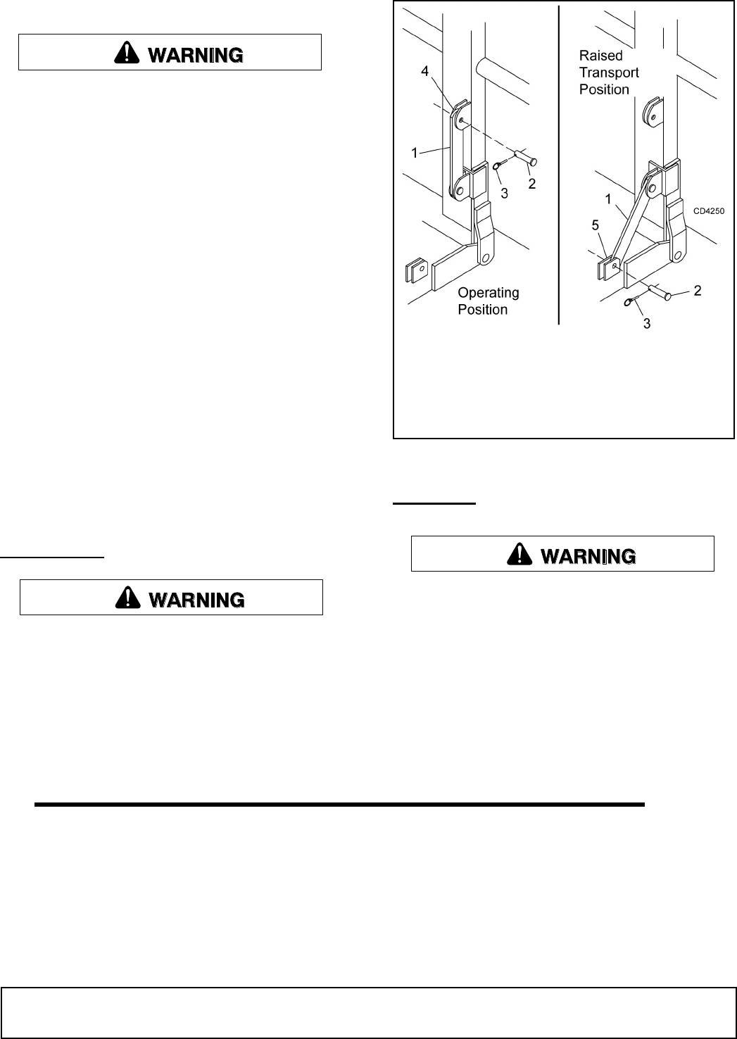
TRANSPORT
■ Before transporting, stop tractor PTO, raise
cutter center section, then raise cutter head and
install transport bar. A raised cutter head can fall
and crush. Keep away; never go underneath. Lower
cutter head after transport and for storage.
When transporting the machine or working on the
underside, attach lock-up bar (1) to center frame (5),
using clevis pin (2), and secure with klik pin (3).
Figure 2. Lock-Up Bar
STORAGE
Do not disconnect hydraulic lines until machine
is securely blocked or placed in lowest position
and system pressure is released by operating
valve levers.
When unhooking and parking the cutter, lower cutter
head to ground. Place 12" blocks under both ends of
the center frame. Lower center frame until 3-point arms
are released and then disconnect. Be sure to discon-
nect PTO and hydraulic lines before moving tractor
away.
1. Transport lock-up bar
2. Clevis pin
3. Klik pin
4. Cutter storage lug
5. Center frame transport lug
(Rev. 1/23/2009)
Owner Service 17
29977 (Rev. 1/23/2009)
OWNER SERVICE
The information in this section is written for operators
who possess basic mechanical skills. If you need help,
your dealer has trained service technicians available.
For your protection, read and follow the safety informa-
tion in this manual.
■ For service and adjustments, lower center
frame and cutter head to ground and disconnect
cutter driveline from tractor PTO. Raise as needed
for working room and securely block all sections of
this equipment before working underneath. Block-
ing up prevents cutter dropping from hydraulic
leak down, hydraulic system failures, or mechani-
cal component failures.
■ When transporting the machine or working on
the underside, attach lock-up bar as shown on
page 16.
Make sure shields and guards are properly
installed and in good condition. Replace if damaged.
Do not disconnect hydraulic lines until machine
is securely blocked or placed in lowest position
and system pressure is released by operating
valve levers.
Operate tractor PTO at 540 RPM (1000 RPM on Q
Series cutters). Do not exceed.
Always wear relatively tight and belted clothing
to avoid getting caught in moving parts. Wear
sturdy, rough-soled work shoes and protective
equipment for eyes, hair, hands, hearing, and head;
and respirator or filter mask where appropriate.
LUBRICATION
■ Lower cutter head to ground, shut off tractor
engine and remove key before servicing.
Do not let excess grease collect on or around parts,
particularly when operating in sandy areas.
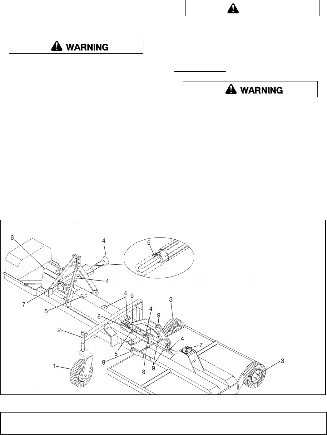
Figure 3 shows the lubrication points. The chart gives
the frequency in operating hours based on normal
operating conditions. Severe or unusual conditions
may require more frequent lubrication. Some reference
numbers have more than one location; be sure to
check number of points.
Use an SAE multi-purpose type grease. Be sure to
clean fitting thoroughly before using grease gun.
Use a good quality 90W gear lube in gearboxes.
Figure 3. Lubrication Points
CAUTION
REF DESCRIPTION FREQUENCY
1 Tailwheel Daily
2 Tailwheel Pivot Daily
3 Gauge Wheels Daily
4 U-Joint 10 Hours
5 PTO Shaft (Lube all 4
sides)
10 Hours
6 PTO Cross Shaft 10 Hours
7 Gearbox (1/2 full of 90W
gear lube)
10 Hours
8 Bearing Blocks (one pump
w/grease gun)
24 Hours
9 Lift Pivot Bushing (oil) Daily
18 Owner Service
29977 (Rev. 1/23/2009)
BLADE SERVICING
NOTICE
■ Do not handle blades with bare hands. Care-
less or improper handling may result in serious
injury.
Raise wings and lock in up position. Inspect blades
before each use to determine that they are properly
installed and in good condition. Check to be sure
blades are snug but still swivel on blade pin (see Blade
Installation). Replace any blade that is bent, exces-
sively nicked, worn or has any other damage. Small
nicks can be ground out when sharpening.
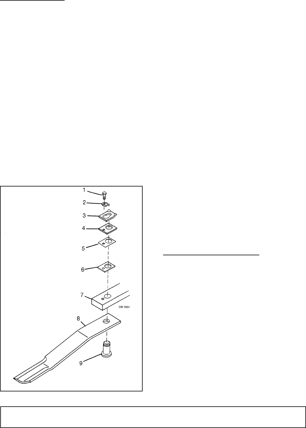
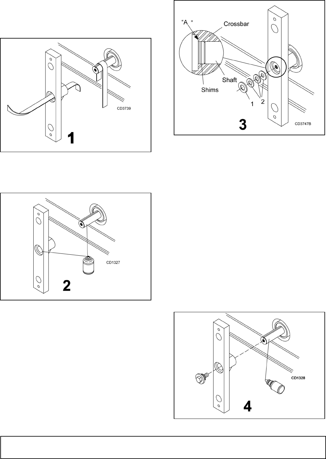
Blade Removal
Align crossbar and blade pin assembly with blade
access hole in cutter frame. Remove bolt (1) and blade
pin lock clip (2). Slide keyhole plate (3) out of blade pin
groove and remove. Remove spacers and drive pin out
of crossbar.
NOTICE
■ If blade is seized in crossbar and extreme force
will be required to remove it, support crossbar
from below to prevent gearbox damage.
Figure 4. Blade Removal
Blade Installation
Apply liberal coating of Never Seez® or equivalent to
blade pin and crossbar hole. Make sure blade is offset
away from deck with cutting edge toward direction of
rotation. Install pin (9) through blade (8) and push up
tightly against crossbar (7). Install as many spacers as
possible, allowing enough space for keyhole plate (3)
to slide into groove of blade pin. Keyhole plate (3) must
be installed with formed ears up as shown. Insert lock
clip (2) over keyhole plate and into blade pin groove
and secure with bolt (1). When installation is complete,
blade should be snug, but still swivel on pin without
excessive force. Retain any spacers not used in shim-
ming blade to be used when either installing new blade
or when blade wear occurs.
NOTICE
■ Crossbar rotation is counter-clockwise when
looking down on the cutter.
■ When sharpening blades grind each blade the
same amount to maintain balance. When replacing
blades, replace in pairs. Unbalanced blades will
cause excessive vibration which can damage gear-
box bearings. Vibration may also cause structural
cracks in cutter housing.
Blade Sharpening
Always sharpen all blades at the same time to maintain
balance. Follow original sharpening pattern. Do not
sharpen blade to a razor edge, but leave at least a
1-1/16" blunt edge. Do not sharpen back side of blade.
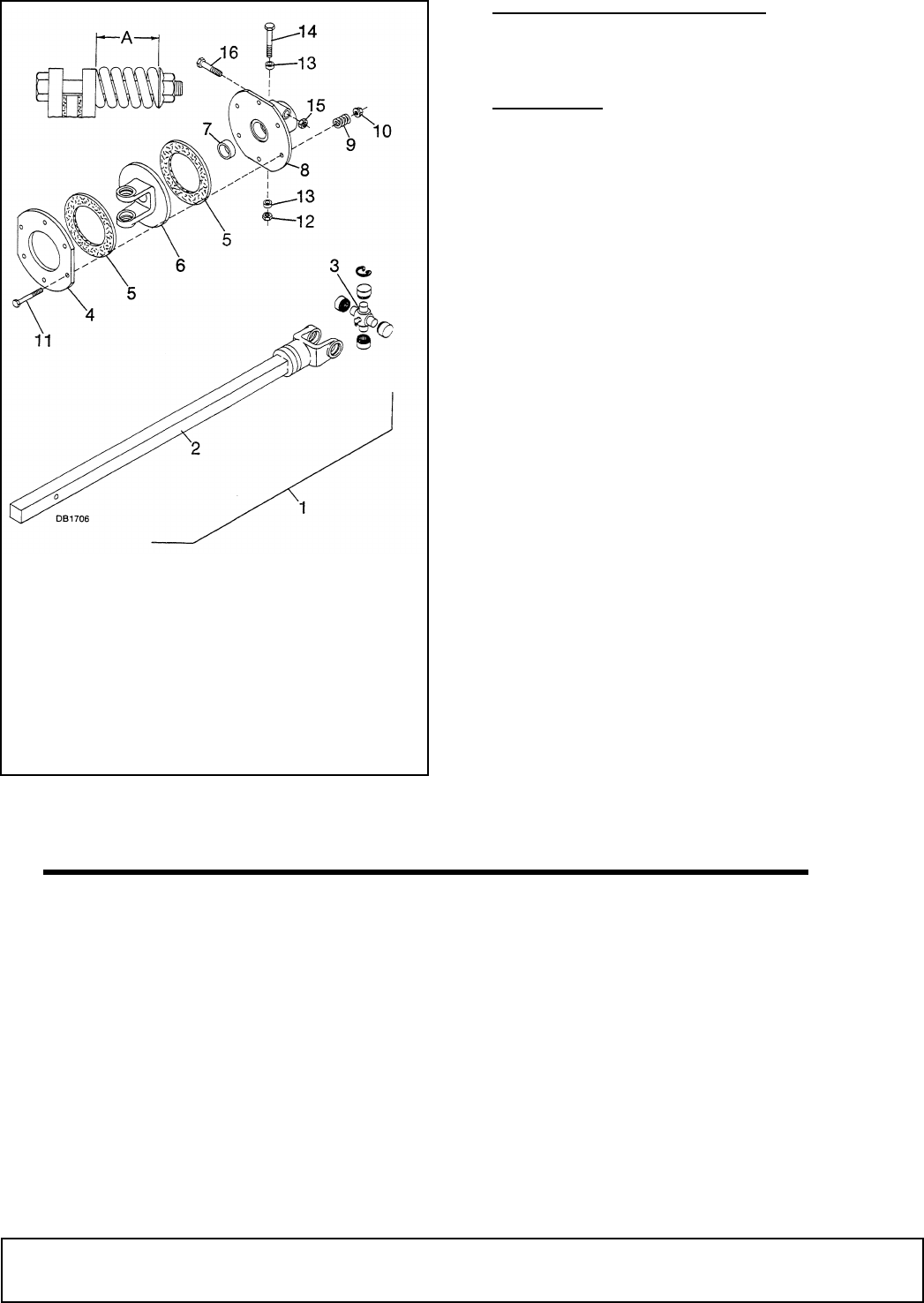
SLIP CLUTCH ADJUSTMENT
A slip clutch is designed to slip, protecting the gearbox
and driveline, should the cutter strike an obstruction.
When a unit sets for a long period of time, such as win-
ter storage, the clutch can rust and seize. When this
occurs, loosen the spring tension and pry clutch plates
apart. Engage PTO and slip clutch. Adjust clutch as
specified.
The maximum the springs should be compressed on a
standard clutch is 1-3/4" at dimension “A”.
For a heavy-duty clutch and wing drive clutches, com-
press springs a minimum of 1-25/32" and a maximum
of 1-13/16" at dimension “A”.
If a clutch continues to slip with springs compressed to
the maximum settings, check friction discs for exces-
sive wear. Discs are 1/8" thick when new. Replace after
1/32" wear. (Minimum disc thickness is 3/32".)
1. 1/2 NC x 1-1/4 HHCS GR5
2. Blade lock clip
3. Keyhole plate
4. 3/16” Spacer
5. Shim, 20 ga
6. Shim, 18 ga
7. Crossbar assembly
8. Blade
9. Blade pin
Owner Service 19
29977 (Rev. 1/23/2009)
Figure 5. Slip Clutch Adjustment
CHAIN SHIELDING REPAIR
Inspect chain shielding frequently. Replace any broken
or missing chains as required.
CLEANING
After Each Use
●Remove large debris such as clumps of dirt, grass,
crop residue, etc. from machine.
●Inspect machine and replace worn or damaged
parts.
●Replace any safety decals that are missing or not
readable.
Periodically or Before Extended Storage
●Clean large debris such as clumps of dirt, grass,
crop residue, etc. from machine.
●Remove the remainder using a low-pressure water
spray.
1. Be careful when spraying near scratched or torn
safety decals or near edges of decals as water
spray can peel decal off surface.
2. Be careful when spraying near chipped or
scratched paint as water spray can lift paint.
3. If a pressure washer is used, follow the advice
of the pressure washer manufacturer.
●Inspect machine and replace worn or damaged
parts.
●Sand down scratches and the edges of areas of
missing paint and coat with Woods spray paint of
matching color (purchase from your Woods
dealer).
●Replace any safety decals that are missing or not
readable (supplied free by your Woods dealer).
See Safety Decals section for location drawing.
1. Clutch
2. Yoke & square shaft
3. Clutch back-up plate
4. Clutch back-up plate
5. Friction disc
6. Yoke & plate asy
7. Bushing
8. Clutch hub w/bushing
9. Compression spring
10. Flange lock nut
11. Bolt
12. Lock nut
13. Sleeve
14. Bolt
15. Nut
16. 5/8 NC x 3-1/2 Bolt

20 Trouble Shooting
29977 (Rev. 1/23/2009)
TROUBLE SHOOTING
Problem Possible Cause Solution
Does not cut Dull blades Sharpen blades.
Worn or broken blades Replace blades. (Replace pairs
only.)
Incorrect PTO speed Be sure PTO speed is set at 540 or
1000 RPM. Make sure to check
your unit’s rated PTO speed.
Ground speed too fast Reduce ground speed.
Drive not functioning (blades do
not turn when PTO is running)
Check drive shaft connection.
Check gearbox.
Gearbox malfunction Repair gearbox.
Excessive clutch slippage Adjust clutch.
Streaks or gives rugged cut Broken or worn blades Replace or sharpen blades.
Ground speed too fast Reduce ground speed.
Excessive cutting height Lower cutting height. (Note: Set
height so blades do not frequently
hit ground.)
Excessive lush and tall vegetation Recut at 90° to first pass.
Thrown objects No shielding Use chain shielding.
Excessive side skid wear Running with skids continuously
on ground
Set skids above ground.
Excessive clutch slippage Clutch out of adjustment Adjust clutch.
Clutch discs worn Replace discs.
Blades hitting ground Raise cutting height.
Vibration Broken blade Replace blades in pairs.
Excessive side skid wear Running with skids continuously
on ground
Use gauge wheels on cutter head.
Wing will not raise Low oil Add hydraulic fluid.

Dealer Service 21
29977 (Rev. 1/23/2009)
DEALER SERVICE
The information in this section is written for dealer ser-
vice personnel. The repair described herein requires
special skills and tools. If your shop is not properly
equipped or your mechanics are not properly trained in
this type of repair, you may be time and money ahead
to replace complete assemblies.
■ Lower cutter to ground, turn tractor engine off
and remove key before performing any mainte-
nance or service.
■ When completing a maintenance or service
function, make sure all safety shields are in good
condition and properly installed before placing cut-
ter in service.
■ Always use personal protection devices such
as eye and ear protection when performing mainte-
nance and service functions.
GEARBOX MAINTENANCE
Read this complete section before any repair. Many
steps are dependent on each other.
Always maintain gearboxes half full of 90W gear lube.
Be sure proper vent plugs are installed in wing gear-
boxes.
Troubleshooting is an important part of gearbox main-
tenance. Check for leakage and bad bearings.
Leakage may be caused by a vent plug not venting.
The vent plug has an internal relief valve set at approx-
imately 5 psi. Remove plug, apply low air pressure to
bottom of plug, and be sure it is venting out the top.
Operating gearboxes over half full of gear lube may
also cause seals to leak. Also check for cracks in hous-
ing. If either of these conditions exists, correct them,
clean up area where leakage was evident, put cutter
back into service and check area for leakage.
Bearing misadjustment or failure is indicated by noise
and excessive side and end play in gear shafts. If
noted, readjust bearings or disassemble and inspect
bearings. Excessive end play in vertical shafts may
also indicate crossbars are not properly shimmed.
Leakage may occur at these points: top cover, vertical
or horizontal seals and at the square ring between side
housings and gearbox.
Leakage is a very serious problem and must be cor-
rected immediately.
Leakage at the horizontal seal, top cover, or between
the housing and side covers and side gear housings
can be corrected without removing gearbox from cutter.
The sealant recommended for gearbox repair is Per-
matex Aviation 3D Form-A Gasket® or equivalent.
Leakage Repair
Repair top cover leakage by removing and cleaning top
cover and top of gearbox.
Use care to prevent foreign material from entering the
gearbox. Apply a thin coat of Permatex to top of gear-
box and cover bolts. Install a new gasket and replace
cover.
Repair horizontal seal or leakage between side hous-
ing and gearbox, remove top cover and siphon gear
lube from box. Remove the leaking seal and replace
(refer to Seal Installation). Use care to prevent rolling
seal lip under. Repair leakage between side housing
and gearbox by removing housing and replacing
square O-ring. Be sure to reinstall shims when install-
ing side housing.
Seal Installation
Proper seal installation is important. An improperly
installed seal will leak and could result in gearbox fail-
ure.
Clean area in housing or cap where seal outer diame-
ter seats and apply a thin coat of gasket sealant.
Inspect gear shafts and sleeves. Pay specific attention
to areas where seals seat. Check for cracks, grooves,
nicks or bumps. Replace housing, shaft or sleeve if
damage cannot be repaired by resurfacing with emery
cloth.
Lubricate seal lip and carefully guide over sleeve or
shaft using a blunt tool such as a letter opener. Be
careful not to roll seal lip under. Do not use a knife
blade as it will nick and ruin seal.
Place seal squarely on housing (spring-loaded lip
toward inside of gearbox). Select a seal driver, a piece
of pipe or tubing with an OD that will set on outside
edge of seal but will clear housing. A driver that is too
small will bow seal cage and ruin seal.
Carefully press seal into housing, preventing distortion
to metal seal cage. Seat vertical seal firmly and
squarely against machined surface and horizontal seal
flush with housing.
Distortion to seal cage or damage to seal lip will cause
seal to leak. Remove and replace seals damaged in
installation.
CAUTION

22 Dealer Service
29977 (Rev. 1/23/2009)
Removing Gearbox from Cutter
Remove safety shielding. Remove top cover and
siphon gear lube from gearbox. Remove drive lines.
Remove crossbar (see Crossbar Removal). Remove
gearbox from cutter.
Gearbox Assembly - Cutter Head
Press cups into main housing until they seat against
machined shoulders. Press bearings onto shafts until
they seat against machined surface next to gear.
Install vertical shaft into gearbox housing, and horizon-
tal shaft into horizontal housing, then press bearings on
with sleeve until all free play is removed (similar to
adjusting front wheel bearings on an automobile).
Check by spinning housing. It should turn freely.
If bearings are too tight, hold housing and rap gear
shaft with a lead hammer. Do not leave bearings
adjusted too tight. Proper adjustment is essential to
good bearing lift.
Install the vertical and horizontal shaft seals.
After seating the seal on the vertical shaft, depending
on when the gearbox was manufactured there are two
options:
1. Place a 1-5/8 ID x 2-31/32 OD washer over the
shaft and into the neck of the gearbox housing. You
will need to tap this washer in place until the
gearbox is installed on the cutter.
2. Press a 1-5/8 ID x 2-3/4 OD washer and a washer
retainer firmly against the seal.
Bearing adjustment on the vertical shaft is set with the
sleeve and maintained with proper crossbar shimming.
Bearing adjustment on the horizontal shaft is set with
the sleeve and maintained by tightening a large hex nut
against the sleeve, installing a dowel plug in the nut
and tightening a set screw against the dowel. Prior to
installing the nut, clean the threads on the nut and the
shaft and apply two drops of Loctite on the threads.
Horizontal Housing Installation
With the housing assembled, place the square O-ring
on the housing and install to gearbox, tighten the four
bolts evenly. Turn the gears against each other to
determine how they rotate. They should turn freely. If
there is a spot where they turn hard, install a gasket
between the horizontal housing and gearbox.
Gearbox Assembly - Input
Press cups into main housing until they seat against
machined shoulders. Press bearings onto shafts until
they seat against machined surface next to gear.
Install input shaft into gearbox housing, then press
bearing on with sleeve until all free play is removed
(similar to adjusting front wheel bearings on an auto-
mobile). Check by spinning housing. It should turn
freely.
If bearings are too tight, hold housing and rap gear
shaft with a lead hammer. Do not leave bearings
adjusted too tight. Proper adjustment is essential to
good bearing life.
Install input shaft seal.
Bearing adjustment on the input shaft is set with the
sleeve and maintained by tightening a large hex nut
against the sleeve, installing a dowel plug in the nut,
and tightening the set screw against the dowel. Prior to
installing the nut, clean the threads on the nut and the
shaft and apply two drops of Loctite on the threads.
Output Shaft Installation
Place the square O-ring on the housing and install to
gearbox, tightening the four bolts evenly. Turn the
gears against each other to determine how they rotate.
They should turn freely without bearing end play. If
there is a spot where they turn hard, install a gasket
between housing and gearbox. If there is bearing end
play, remove gasket.
Install seals on both ends of shaft.
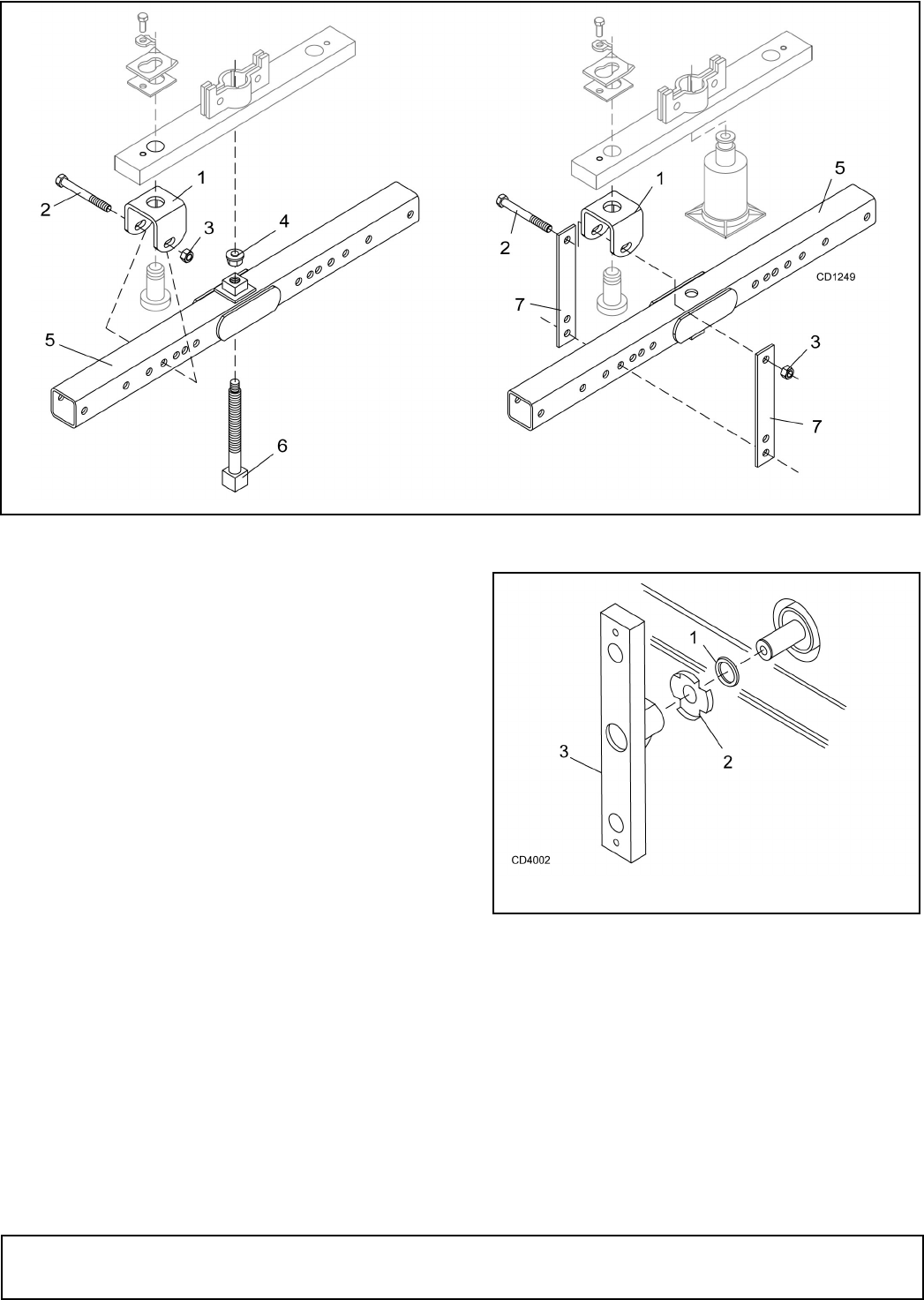
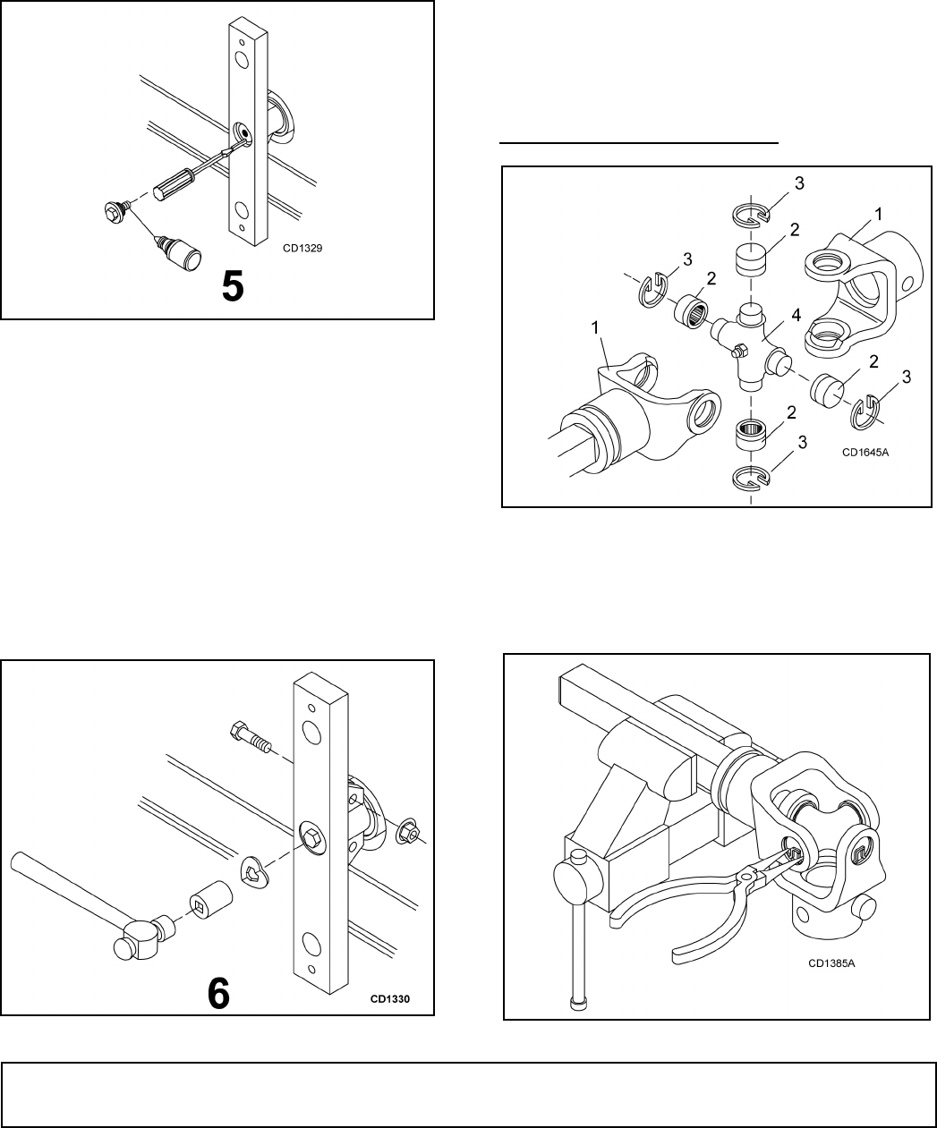
CROSSBAR
Removal
For crossbar removal, it is necessary to gain access to
bottom side of cutter. Raise cutter and securely block
up. You may use either puller screw (6) or a small
hydraulic jack to remove crossbar. See Figure 6.
Loosen bolts on crossbar clamp. Remove bolt retaining
washer by prying washer up and breaking weld.
Remove washer and bolt. Remove blades from cross-
bar (see page 18). Assemble clevises (1) to each end
of crossbar, utilizing blade pins, spacers, keyhole
plates and blade pin clips.
Position tube assembly (5) with threaded nut toward
crossbar. Install pad assembly (4) in nut on square tube
assembly.
Bolt square tube assembly to the clevises using 5/8" x
4-1/2" bolts (2). Insert puller screw assembly (6) into
square tube assembly (5) and tighten against pad
assembly (4) an gear shaft as shown. For best results,
strike head of puller screw with a sledge hammer while
tightening screw with a wrench. If crossbar has been
installed with Loctite, it may be necessary to apply heat
(greater than 500°F) to crossbar to break Loctite bond.
Dealer Service 23
29977 (Rev. 1/23/2009)
Figure 6. Crossbar Puller
To remove crossbar with hydraulic jack, install the cle-
vis (1) using the blade pin spacers, keyhole plates and
bolts to each end of crossbar. Position square tube (5)
with threaded nut portion down.
Attach square tube to the clevises using crossbar puller
links (7) to space it away from crossbar. Place hydrau-
lic jack on square tube so end of jack presses against
end of gearbox shaft. Slowly apply force with hydraulic
jack.
NOTE: Hydraulic jack will not operate if tipped more
than 90°. It may be necessary to apply heat to break
Loctite bond on crossbar. Use caution to prevent bend-
ing crossbar when using either removal method.
Installation
The anti-wrap washer (2) was added as an inline pro-
duction change. Your cutter may not be equipped with
the anti-wrap washer (2). It is designed to minimize for-
eign material wrapping around the gear shaft and caus-
ing seal damage. You may order an anti-wrap kit for
installation on your cutter.
Select the 1-5/8" ID x 2-5/16" OD x 7 GA washer (1)
from the shim pack and install as shown. Install the
anti-wrap washer (2) next to the 7 GA washer as
shown.
Figure 7. Anti-Wrap Washer Installation
Shimming
A properly shimmed crossbar is essential to obtain
good gearbox bearing life. Make sure the gearbox ver-
tical shaft bearing adjustment is correct. Bearings
should be just tight enough to remove all free play. You
should feel a slight drag caused by the seals, but not
enough drag to indicate pre-loaded bearings.
1. Clevis
2. 5/8" x 4-1/2" Bolt
3. 5/8" Nut
4. Pad assembly
5. Tube assembly
6. Puller screw assembly
7. Crossbar puller link
1. 1-5/8 x 2-5/16 x 7ga Washer
2. Anti-wrap washer
3. Crossbar
24 Dealer Service
29977 (Rev. 1/23/2009)
NOTICE
■ Incorrectly shimmed crossbars can cause
costly damage to bearings and gearboxes. Follow
these steps to obtain a properly shimmed crossbar.
Figure 8
1. Using emery cloth (220 or finer), remove surface
rust, Loctite and foreign material from gearbox
vertical shaft and hole in crossbar.
Figure 9
2. Apply Locquic® primer to gearbox vertical shaft
and hole in crossbar. Wipe off with clean cloth and
reapply. This reduces Loctite curing time. Do not
reapply blue Loctite until all solvent smell has
gone.
NOTE: Omit step 2 when installing a clamp-type
crossbar.
Figure 10
NOTICE
■ Failure to accomplish step three as outlined
will result in an improperly shimmed crossbar and
gearbox bearing failure.
3. Install crossbar on gearbox vertical shaft without
key in keyway. Make sure crossbar is seated firmly
against washer covering oil seal in gearbox neck.
Do not drive crossbar on vertical shaft. If crossbar
will not install easily, repeat step one until it will.
Select shim pack. Add shims until they are level
with shoulder in crossbar (point A).
The washer (1) should only be used if using anti-
wrap washer.
Press shims in place very tightly and feel to see if
more shims are needed. When you reach the point
where adding one more shim will extend above
crossbar shoulder, do not add that shim.
Figure 11
1. 3/4 x 2-1/2 x 1/4
Flat washer
2. Shims
Dealer Service 25
29977 (Rev. 1/23/2009)
4. When you are certain you have correctly
determined the proper shim pack, remove crossbar
and apply blue Loctite retaining compound to
vertical shaft. When fit between shaft and crossbar
is tight, use Loctite sparingly. When fit is loose,
completely coat the shaft.
NOTE: Do not apply Loctite to vertical shaft when
installing a clamp type crossbar.
Figure 12
5. Install crossbar on vertical shaft and push keys into
keyway with screwdriver. Do not drive key in with a
hammer, as this could loosen vertical shaft
bearings. Clean crossbar bolt threads and apply a
few drops of red Loctite.
Install 1/4" thick washer and shim pack, selected in
step three, on bolt. Install bolt into vertical shaft and
torque to 300 lbs-ft.
With crossbar installed, recheck gearbox bearings
for excessive drag or presence of free play. If either
excessive drag or any free play is detected, repeat
step three.
Figure 13
6. When installing a clamp-type crossbar, install
clamp bolts and torque to 85 lbs-ft.
Install crossbar block lock over bolt head. Place a
socket over bolt and drive in lock until it is com-
pletely flat.
NOTE: If drive-in type crossbar bolt lock is not
available, the weld-on lock may be reused. Install
lock over bolt head and weld it to the crossbar with
a 1/2" long weld.
NOTICE
■ Attach welder ground directly to crossbar. Fail-
ure to do so can ruin gearbox bearings.
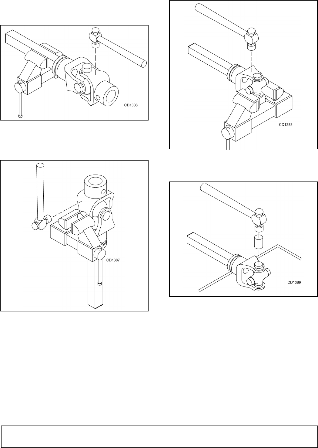
UNIVERSAL JOINT REPAIR
Figure 14. U-Joint Exploded View
U-Joint Disassembly
1. Remove external snap rings from yokes in four
locations as shown in Figure 15.
Figure 15
1. Yoke
2. Cup and bearings
3. Snap ring
4. Journal cross
26 Dealer Service
29977 (Rev. 1/23/2009)
2. With snap rings removed, support drive in vise,
hold yoke in hand and tap on yoke to drive cup up
out of yoke. See Figure 16.
Figure 16
3. Clamp cup in vise as shown in Figure 17 and tap
on yoke to completely remove cup from yoke.
Repeat step 2 & step 3 for opposite cup.
Figure 17
4. Place universal cross in vise as shown in Figure 18
and tap on yoke to remove cup. Repeat step 3 for
final removal. Drive remaining cup out with a drift
and hammer.
Figure 18
U-Joint Assembly
Figure 19
1. Place seals securely on bearing cups. Insert cup
into yoke from outside and press in with hand
pressure as far as possible. Insert journal cross
into bearing cup with grease fitting away from
shaft. Be careful not to disturb needle bearings.
Insert another bearing cup directly across from first
cup and press in as far as possible with hand
pressure.
2. Trap cups in vise and apply pressure. Be sure
journal cross is started into bearings and continue
pressure with vise, squeezing in as far as possible.
Tapping the yoke will help.
3. Seat cups by placing a drift or socket (slightly
smaller than the cup) on cup and rap with a

Dealer Service 27
29977 (Rev. 1/23/2009)
hammer. See Figure 19. Install snap ring and
repeat on opposite cup.
4. Repeat step 1 & step 2 to install remaining cups in
remaining yoke.
5. Move both yokes in all directions to check for free
movement. If movement is restricted, rap on yokes
sharply with a hammer to relieve any tension.
Repeat until both yokes move in all directions
without restriction.
SPRING-LOADED
WHEEL YOKE ADJUSTMENT
Tighten elastic stop nuts on spring bolts until 1/4" of
bolt thread extends through nut.
1-SPOOL, 3-WAY VALVE
This valve is an extremely closely-fitted unit. Great cau-
tion should be taken to keep all dirt and impurities out
of it. Any foreign matter could ruin sealing surfaces.
Open-Center or Closed-Center
This valve can be used with tractors having either a
closed-center or open-center hydraulic system. The
valve, as shipped, is ready for use with open-center
systems. To adapt it for use with closed-center sys-
tems, remove the plug adjacent to the outlet port and
replace with the power-beyond sleeve and plug
included in box of parts. Also, reset pressure relief
valve to a closed position by removing cap (45) and
turning adjustment screw (43) all the way in. Replace
cap (45).
In operation, an open-center system allows oil to flow
freely through valve when all spools are in neutral. it is
used on most tractor systems. The closed-center valve
is blocked, allowing no oil to circulate when spools are
in neutral. This system is used on late model John
Deere 3010, 4010, etc., Ford model 6000, and MF
models 1100 and 1130.
Operation
The valve spool is equipped to operate a single-acting
cylinder and has a float position detent. The spool will
automatically return to neutral when not in detent. With
spool in neutral, cylinder will be held in position.
Servicing
Spool Sticking
Any tendency of spools to stick in position is usually
caused when mounting bolts are pulled down too tight,
or the valve is mounted on an uneven surface. Also,
excessive pressure will make spools stick.
Lift Check Service
The load lift checks are used to prevent a load from
dropping prior to starting to raise when the spool is
being moved slowly to the raised position from neutral.
If these checks leak by, so that the load does not hold
properly, remove lift checks, inspect the check and
seats, and replace if necessary.
Spool Removal
The spool is selectively fitted in body and cannot be
interchanged or exchanged. However, it may be
removed to replace seals, but it is not necessary that it
be removed completely. To replace seals on any spool,
remove handle and snap ring, then push spool far
enough out back of valve to expose V-cup seal on han-
dle end. Remove and replace with new seal V-cup fac-
ing inward. Remove retaining screw from other end of
spool. Slide spool through the new seal, being careful
not to roll over the edge. Slide forward far enough to
expose the seal in back of valve. Replace it the same
way, slip spool back into its normal position, and reas-
semble.
Fitting leakage
Use a thread sealant on all fittings to prevent leakage.

28 Dealer Check List
29977 (Rev. 1/23/2008)
DEALER CHECK LISTS
PRE-DELIVERY CHECK LIST
(DEALER’S RESPONSIBILITY)
Inspect the equipment thoroughly after assembly to
ensure it is set up properly before delivering it to the
customer.
The following check lists are a reminder of points to
inspect. Check off each item as it is found satisfactory
or after proper adjustment is made.
___ Check that all safety decals are installed and in
good condition. Replace if damaged.
___ Check that shields and guards are properly
installed and in good condition. Replace if dam-
aged.
___ Properly attach implement to tractor and make all
necessary adjustments.
___ Check all bolts to be sure they are tight.
___ Check and grease all lubrication points as identi-
fied in “Service”.
___ Check that blades have been properly installed.
DELIVERY CHECK
(DEALER’S RESPONSIBILITY)
___ Instruct customer how to lubricate and explain
importance of lubrication.
___ Point out the safety decals. Explain their meaning
and the need to keep them in place and in good
condition. Emphasize the increased safety haz-
ards when instructions are not followed.
___ Present Operator's Manual and request that cus-
tomer and all operators read it before operating
equipment. Point out the manual safety rules,
explain their meanings and emphasize the
increased safety hazards that exist when safety
rules are not followed.
___ Show customer the safe, proper procedures to be
used when mounting, dismounting, and storing
equipment.
___ Point out all guards and shields. Explain their
importance and the safety hazards that exist
when not kept in place and in good condition.

Assembly 29
29977 (Rev. 1/23/2009)
ASSEMBLY
DEALER SET-UP INSTRUCTIONS
Assembly of this cutter is the responsibility of the
Woods dealer. It should be delivered to the owner com-
pletely assembled, lubricated, and adjusted for normal
cutting conditions.
The cutter is shipped partially assembled. Assembly
will be easier if aligned and loosely assembled before
tightening hardware. Recommended torque values for
hardware are located in the Bolt Torque Chart on
page 54.
Full chain shielding must be installed when
operating in populated areas or other areas where
thrown objects could injure people or damage
property.
• If this machine is not equipped with full chain
shielding, operation must be stopped when any-
one comes within 300 feet (92 m).
• This shielding is designed to reduce the risk
of thrown objects. The mower deck and protec-
tive devices cannot prevent all objects from
escaping the blade enclosure in every mowing
condition.
It is possible for objects to ricochet
and escape, traveling as much as 300 feet (92 m).
Make sure spring-activated locking pin or collar
slides freely and is seated firmly in tractor PTO
spline groove.
Operate tractor PTO at 540 RPM (1000 RPM on Q
Series cutters). Do not exceed.
Always wear relatively tight and belted clothing
to avoid getting caught in moving parts. Wear
sturdy, rough-soled work shoes and protective
equipment for eyes, hair, hands, hearing, and head;
and respirator or filter mask where appropriate.
Drive Shaft Installation
Cut Drive Shields
NOTE: The driveline shielding must be cut to dimen-
sions given before installing of front drives.
1. Remove approximately 1-inch of material from bell
shield so it will not interfere with slip clutch during
operation. See Figure 20.
Figure 20. Slip Clutch Bell Shield
2. Cut slip clutch drive shield to 8-3/4" as shown in
Figure 21.
Figure 21. Slip Clutch Drive Shield
3. Cut front half of drive shield to 6-1/2" for standard
length drive as shown in Figure 22. Cut optional
long drive shield to 13-1/4".
Figure 22. Front Drive Shield, Standard Drive Shown
CAUTION
Remove 1"
DP1
8-3/4"
DP3
6-1/2"
DP2

30 Assembly
29977 (Rev. 1/23/2009)
Install Drive Shaft
See parts drawing on page 36.
Slide clutch and square shaft assembly onto gearbox
shaft, using two 1/4" keys. Secure with 7/16 hex bolt
through cross hole and tighten securely. Slip tubular
outer drive assembly (19) over square shaft until
closed. Install shield (42) on top of gearbox and secure
with 5/8 NC lock nuts (76).
Mounting A-Frame on Center Frame
See parts drawing on page 36.
Attach A-frame half (16) to inside surface of mounting
arms, using Category 2 mounting pin (14). Secure with
1-1/8 NF slotted hex nut (95). After assembling both
sides of A-frame, assemble clevis pin (82) through top
hole of A-frame halves. Secure clevis pin with two cot-
ter pins (56).
Secure A-frame brace bars (6) to outside of attaching
lugs with two 3/4 x 2 hex head cap screws, lock wash-
ers and nuts. Attach top of brace bar to A-frame, using
3/4 x 4-1/2 hex head cap screw. Be sure brace bars
and sleeve (89) are installed in bottom hole and
between A-frame halves. Tighten all bolts securely.
Torque hitch pin nuts to 300 lbs-ft and secure with cot-
ter pins (56).
Connect top link and adjust so frame rides approxi-
mately level. Connect front drive shaft to PTO shaft of
tractor so that lock pins snaps into groove of PTO shaft.
Be sure drive has adequate engagement and does not
bind or bottom in any position. Optional longer drive is
available.
Lift Cylinder Installation
See parts drawing on page 36.
Remove shield (26). Connect lift arm (10) by using a
1-1/8 x 7" clevis pin (94) through frame and secure with
a 1/4 x 1-3/4 cotter pin (57). Be sure pin is installed
pointing forward. If installed pointing backwards, the
end will interfere with and damage drive shaft.
Install cylinder butt end to lug located on the cross
channel of center frame by using pin furnishing in butt
end of cylinder. Discard pin in rod end and replace with
1 x 3" clevis pin (93) found in bag of parts. Remember
to install pin pointing forward or damage to drive shaft
will result. Connect rod end to lift arm by using the 1 x
3" clevis pin (93). Secure with a 1/4 x 1-1/2 cotter pin
(56). Be sure sleeve (91) is installed in lift arm as
shown and that the check valve plug (8) in base of cyl-
inder is on bottom side and rod end fitting is on top.
Install a 1/2 x 1/4 reducing bushing followed by a 1/4"
90° swivel street 1/16 restrictor elbow in end of cylin-
der. Use pipe thread compound and tighten securely.
Position with port pointing inward.
Connect 1/4 x 90" long hydraulic hose (20) to swivel fit-
ting. Run hose through loop provided on mounting arm
and using rubber binding strap, attach hose to A-frame
where it will stay clear of slip clutch. The front end of
this hose must be connected to tractor hydraulic sys-
tem. If the tractor has a valve, or if you are using the
control valve (35), it must be connected as shown.
It is desirable to connect the hose through a quick cou-
pler, if provided, on the tractor. A 1/2 x 1/4 reducing
bushing is provided to adapt to the tractor quick cou-
pler.
If a Woods valve is used, connect end of this hose to
quick coupler provided with valve. To other end of quick
coupler, connect the 36" hydraulic hose furnished with
valve. Connect hose to top port of valve.
Attaching Cutter Head to Center Frame
Position center frame attaching lugs between center
plates of cutter. Install 3/4 x 1-1/8 x 5/8" bushing (88) in
center plates of cutter in four places. Also install two
bushings (98) in lugs of center frame. Secure with two
3/4 x 3" hex head cap screws (80) and a flat washer
(87), both under head and outside. NOTE: Be sure bolt
is installed from inside out as shown on page 36. Add
3/4" hex lock nut (86) and torque to 300 lbs-ft.
Lift Link Installation
Connect clevis lift link (21), page 38, between lift arm
and cutter frame as shown, using two 1 x 2-1/2" clevis
pins (60) and cotter pins (46).
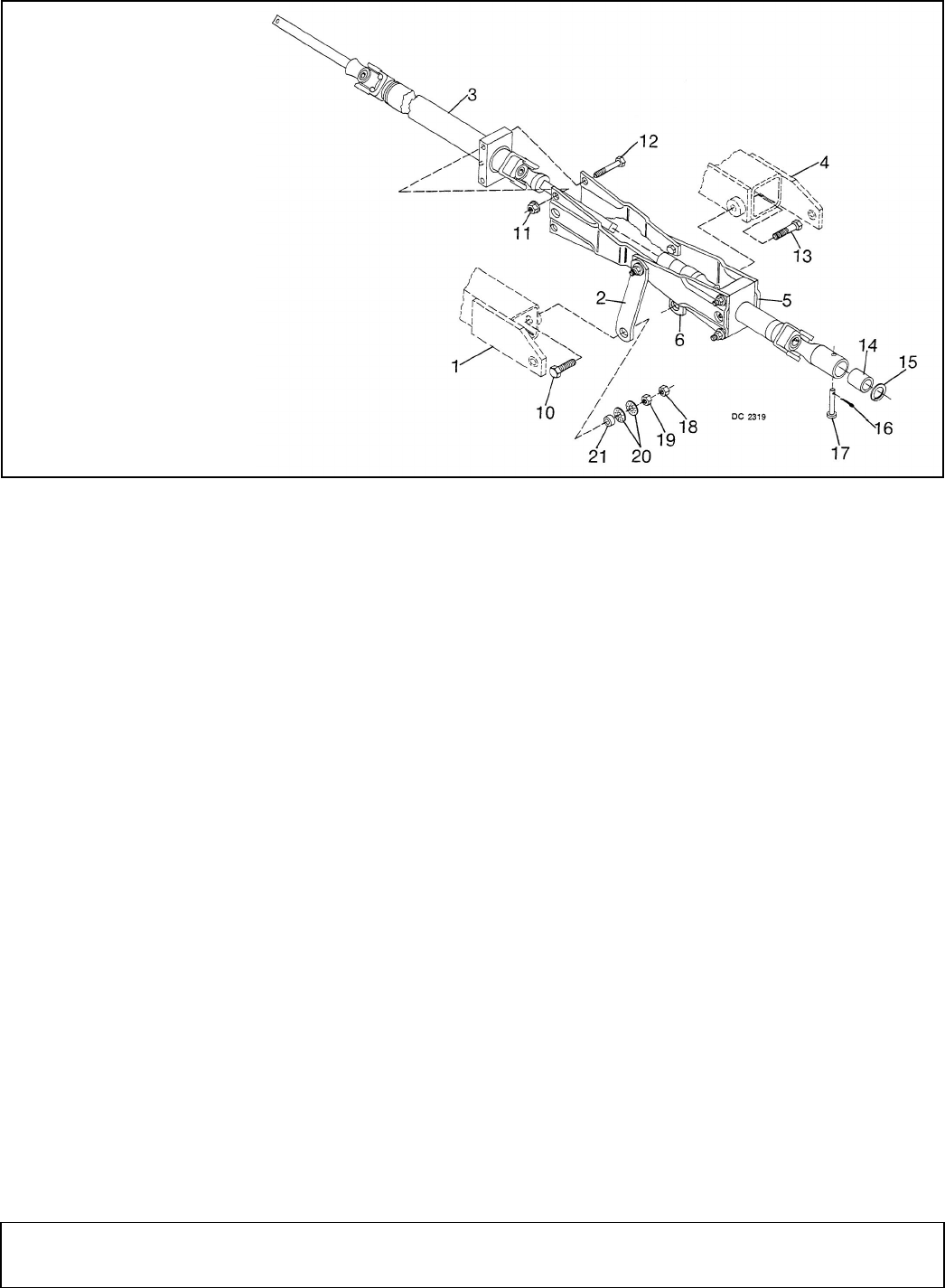
Assembly 31
29977 (Rev. 1/23/2009)
Side Drive Installation (Figure 23)
Figure 23. Side Drive Installation
Assemble inner drive assembly (3) into outer drive
assembly (5). Check to ensure drive shaft and U-joints
are indexed properly. The small pin on end of square
shaft should mate with outer drive for proper installa-
tion. Place offset plates of side drive assembly over
bearing block of inner drive assembly, and attach with
bolts (12) and lock nuts (11). Do not tighten hardware
at this time.
Install inner shear sleeve (14) into end of U-joint sleeve
and work snap ring (15) into groove to retain shear
sleeve (14).
Install inner drive (3) into gearbox on center section.
With keys in place in cutter head gearbox shaft, slide
outer drive onto shaft, align hole in inner shear sleeve,
gear shaft and U-joint sleeve and install hard shear pin
(17). Retain with cotter pin (16).
Attach drive joint support arms (23 & 6) to side drive
mounting points (1 & 4). Insert bolt (10) through hole in
mounting point (1), place sleeve (21) over bolt, and
install cup washers (20) with cups toward sleeve. Install
this assembly through support arm (2), apply Loctite) to
bolt, then install jam nut (19) and tighten. Secure with
nut (18).
Repeat this procedure for support arm (6), using bolt
(13).
Insert grease zerk into threaded hole on end cap of
drive shaft shield. For location, see page 36, item 99.
Tighten as required.
Side Shield Installation
Refer to parts drawing on page 36.
Install inner drive shield (49) over outside of plates on
outer drive (1). Tighten all hardware. Attach cylinder
and drive shield (26) with four self-tapping screws.
Install drive shaft shield (5) over end of drive shaft that
protrudes through the center section gearbox with self-
tapping screws.
Cutter Head Gearbox Shield Installation
Refer to page 38.
Remove four gearbox cover bolts. Place shield (34)
over gearbox and reinstall bolts.
Blade Installation
Raise cutter.
The cutter blades are shipped separately.
Remove bolt, spacer plug, keyhole plate and spacer
plates. Drop the blade pin out. Discard shipping spacer.
Install pin upward through blade. Be sure blade is right
side up. Reinstall pin. Replace spacers and keyhole
plate. If the fit is too tight, one of the thin spacers may
be removed. Reinstall spacer plug and bolt. It is not
necessary to torque the bolt excessively.
1. Side drive mounting point
2. Drive joint support arm
3. Inner side drive assembly
4. Side drive mounting point
5. Outer side drive assembly
6. Drive joint support arm
10. 5/8 x 2-1/4" Bolt
11. 1/2" Flanged hex lock nut
12. 1/2 x 5" Bolt
13. 5/8 x 3-1/2" Bolt
14. Inner shear sleeve
15. Snap ring
16. 1/8 x 1" Cotter pin
17. 7/16 x 3" Hard shear pin
18. 5/8" Hex nut
19. 5/8" Hex jam nut
20. Cup washer
21. 5/8 x 1 x 7/16" Sleeve

32 Assembly
29977 (Rev. 1/23/2009)
Tire and Skid Assembly Installation
Refer to parts drawing on page 38.
The mower is shipped with skids assembled to rear
corners.
If tires and wheels are used, assemble the solid lami-
nated tire (24) to cutter frame with one lock washer
(62), and secure with one 1" NF hex nut (61).
If skids are used instead of wheels, install two 3/4 x
2-1/4" hex head cap screws (57), 3/4" standard flat
washers (58), and a 3/4 x 1 x 1-7/8" sleeves (56).
Secure with a 3/4" NC hex lock nuts (59).
Tires or skids may be adjusted up or down for desired
mowing height. Cutter should be adjusted so rear outer
skid does not carry any weight under normal conditions
as it encounters considerable side slipping action when
turning. The inner side skid should be adjusted to pre-
vent cutter from scalping, but so it does not ride on the
ground in normal mowing.
Adjust front skids so they prevent scalping and so they
will carry cutter when the tractor goes through a low
spot. When skids are used, the weight of the cutter
should be carried on the tractor and not on skids or
rapid wear will result. After desired height has been
selected, bolt left and right wheel guards in place.
Secure with 1/2 x 1-3/4" carriage bolt and 1/2" flanged
lock nut.
Lubrication
Fill both center and cutter gearboxes half full of 90 EP
gear lube or similar transmission oil. These boxes are
sealed. If there is no leakage, only occasional oil
checks are required.
Check for leaks in the hydraulic system. On cutter
gearbox, remove top plug and replace with special
vented pipe plug from box of parts.
Checking the Machine
Raise and lower the 3-point hitch very carefully, and be
sure drive shaft does not tend to bottom in any position,
and that it does not come apart or get too loose in any
position. If the drive shaft is too short, there are alter-
nate tubular drive units available.
Raise and lower cutter frame very carefully, being sure
none of the bolt heads interfere with drive linkage, etc.,
and that drive shaft slides freely and works properly.
Cutter should raise to approximately a vertical position.
Start cutter slowly and be sure blades don't interfere
with anything. The drive must operate smoothly and
freely. Now raise and lower the cutter slowly with drive
shaft turning and again check for interferences or prob-
lems.
Adjust so center frame and cutter frame ride with front
slightly lower than rear for normal mowing. For varia-
tions, see instructions in Operation section.
Reinstall the shield on the cutter.
Chain Shielding Installation
Full chain shielding must be installed when
operating in populated areas or other areas where
thrown objects could injure people or damage
property.
• If this machine is not equipped with full chain
shielding, operation must be stopped when any-
one comes within 300 feet (92 m).
• This shielding is designed to reduce the risk
of thrown objects. The mower deck and protec-
tive devices cannot prevent all objects from
escaping the blade enclosure in every mowing
condition.
It is possible for objects to ricochet
and escape, traveling as much as 300 feet (92 m).
Chain shielding is bolted to front and rear of cutter with
a 1/2 x 1-1/4" hex head cap screws (47), and 1/2" NC
flanged lock nuts (49). Chain shielding should be
installed as shown on page 38.
Check Chain Installation
Check chains are used to act as lower limit stops when
lowering center frame. They will also prevent the cutter
from settling when tractor hydraulic system will not hold
the load on the 3-point hitch.
To install, bolt end of chain to diagonal brace of 3-point
hitch in holes provided. Position chain on underneath
side of plate and install bolt up through chain and
through plate. Connect the keyhole hook plates, one on
either side of top link.
It may be necessary to replace top link pivot pins with
long 3/4 x 6" bolt provided. Adjust chains as required to
carry cutter at desired height and angle.
Counterweight Installation (Optional)
This cutter throws a considerable side load on the 3-
point hitch which results in torsion in cross shaft of trac-
tor. If tractor has a fairly small cross shaft, it is advis-
able to use a counterweight on the left of center frame.
This counterweight, as provided, weighs 400 lbs and
bolts in place as shown on page 36. Also “suitcase”
weights may be used in place of the counterweight box.
Use as many as required to attain the 400 lbs counter-
weight. An empty counterweight box may also be pur-
chased which, if filled with steel punch slugs, will weigh
approximately 400 lbs. Use at least 400 lbs; more
weight will not be harmful to the machine and may be
of some help.

Assembly 33
29977 (Rev. 1/23/2009)
Tailwheel (Optional)
The tailwheel is ideal for mowing on relatively level
ground, orchards, etc. It may not be too useful when
mowing ditch banks and rough ground.
To install tailwheel, position angle frame with cross pipe
of tailwheel frame between two forward lugs on center
frame and install long pin provided. Attach spring cup
assembly between the two rear lugs provided on center
frame.
Height adjustment is accomplished by positioning
spring cup attaching bolt into different holes in tailwheel
tubular member. This is a spring-mounted tailwheel
and will absorb some shock loading very well.
Stump Jumper (Optional)
Remove blade pins and blades from crossbar. Remove
straps from pan assembly. Discard 3/16" thick spacer
which is under keyhole plate.
Install one strap on stump jumper. Slide over crossbar.
Install second strap. Align blade pin holes.
Insert blade pin through blade, stump jumper and
crossbar. Secure with keyhole plate, lock plate and 1/2"
bolt. Use as many blade pin shims as necessary so all
freedom is taken from blade pin. Reassemble straps to
pan as shown.
Control Valve Installation (Optional)
The valve provided is a single-spool valve set up for
use with open-center hydraulic systems. Refer to
page 27 for instructions to convert it for use with
closed-center systems. Tractors with closed-center
systems include: Ford, John Deere, MF1100-1300,
Oliver 1755, 1855, 1955 and MM-1968 and later.
If tractor has an open-center system and pump delivers
more than eight gallons per minute continuous flow,
larger hoses and fittings in the valve will be required.
The valves will handle 25 gallons per minute flow. Con-
sult your tractor manual or dealer if necessary for type
and capacity of your tractor hydraulic system.
Position valve on top of bracket as shown and secure
with 3/8 x 2-1/2 bolts. Then position fender bracket on
right hand fender so controls are convenient to the
operator. If it is a narrow-type fender, also use inner
brace (29), installing it on tire side of fender.
Drill four holes in fender and, using back-up bars (28)
provided, bolt bracket to fender. If it is a wide, flat-top
fender, discard inner place and attach main bracket
directly to fender, again drilling four holes and using
back-up bars provided.
Using diagonal brace bar, bending and drilling as
required, to stiffen fender and valve bracket if it is not
rigid enough without it. The narrow extension plate
which extends forward on valve bracket is not used
with single-spool valve and may be knocked off if it is in
the way.
On the inlet (forward) side of valve, install a 1/2 x 3/8"
adapter elbow. Into this, screw the 3/8 x 60" one-wire
braid hydraulic hose. This hose must be attached to the
tractor pressure system wherever it is appropriate. You
may have to consult the tractor manual or your dealer
to find out where to attach this.
On the return (outlet) side of valve, install a 3/4 x 1/2"
reducing bushing followed by a 1/2 x 3/8" 90° adapter
elbow. Position both elbows so hoses lie properly.
Install hose barb (37) into elbow fitting and on this,
push self-clamping, low-pressure return hose. This will
have to return to tractor hydraulic system reservoir at
appropriate spot. Consult your tractor dealer or man-
ual. Install other hose barb to tractor system and cut
hose to desired length. Install on the barbs.
NOTE: Do not slip hose on until you are ready to leave
it as hose cannot be removed from barb without cutting
it.
Install control lever on valve. Screw 3/8 x 1/4" 90°
adapter elbow into top of valve. To it, attach three foot
hose which goes to coupler and cylinder.

34 Assembly
29977 (Rev. 1/23/2009)
NOTES

Parts 35
29977 (Rev. 1/23/2009)
PARTS INDEX
CENTER SECTION ASSEMBLY . . . . . . . . . . . . . . . . . . . . . . . . . . . . . . . . . . . . . . . . . . 36
CUTTER HEAD SECTION ASSEMBLY . . . . . . . . . . . . . . . . . . . . . . . . . . . . . . . . . . . . . 38
TUBULAR SIDE DRIVE ASSEMBLY . . . . . . . . . . . . . . . . . . . . . . . . . . . . . . . . . . . . . . . 40
CUTTER HEAD GEARBOX ASSEMBLY . . . . . . . . . . . . . . . . . . . . . . . . . . . . . . . . . . . . 41
INPUT GEARBOX ASSEMBLY . . . . . . . . . . . . . . . . . . . . . . . . . . . . . . . . . . . . . . . . . . . 42
FRONT HALF OF 2-JOINT DRIVE 35R . . . . . . . . . . . . . . . . . . . . . . . . . . . . . . . . . . . . . 43
SLIP CLUTCH ASSEMBLY . . . . . . . . . . . . . . . . . . . . . . . . . . . . . . . . . . . . . . . . . . . . . . 44
INTEGRAL U-JOINT SHIELDING . . . . . . . . . . . . . . . . . . . . . . . . . . . . . . . . . . . . . . . . . 45
3-1/2" BORE & 8" STROKE HYDRAULIC CYLINDER . . . . . . . . . . . . . . . . . . . . . . . . . . 46
1-SPOOL, 3-WAY VALVE (OPTIONAL). . . . . . . . . . . . . . . . . . . . . . . . . . . . . . . . . . . . . 48
PNEUMATIC TAILWHEEL ASSEMBLY . . . . . . . . . . . . . . . . . . . . . . . . . . . . . . . . . . . . . 49
PNEUMATIC TIRE ASSEMBLY FOR TAILWHEEL . . . . . . . . . . . . . . . . . . . . . . . . . . . . 50
HUB ASSEMBLY FOR PNEUMATIC TAILWHEEL . . . . . . . . . . . . . . . . . . . . . . . . . . . . 50
TAILWHEEL ASSEMBLY . . . . . . . . . . . . . . . . . . . . . . . . . . . . . . . . . . . . . . . . . . . . . . . . 51
TAILWHEEL & GAUGE WHEEL ASSEMBLY . . . . . . . . . . . . . . . . . . . . . . . . . . . . . . . . 52
GAUGE WHEEL & TAILWHEEL HUB & AXLE ASSEMBLY . . . . . . . . . . . . . . . . . . . . . 52
CROSSBAR PULLER ASSEMBLY . . . . . . . . . . . . . . . . . . . . . . . . . . . . . . . . . . . . . . . . 53
STUMP JUMPER (OPTIONAL) . . . . . . . . . . . . . . . . . . . . . . . . . . . . . . . . . . . . . . . . . . . 53
Rotary Cutters:
S105-3, S106-3, S105Q-3 & S106Q-3
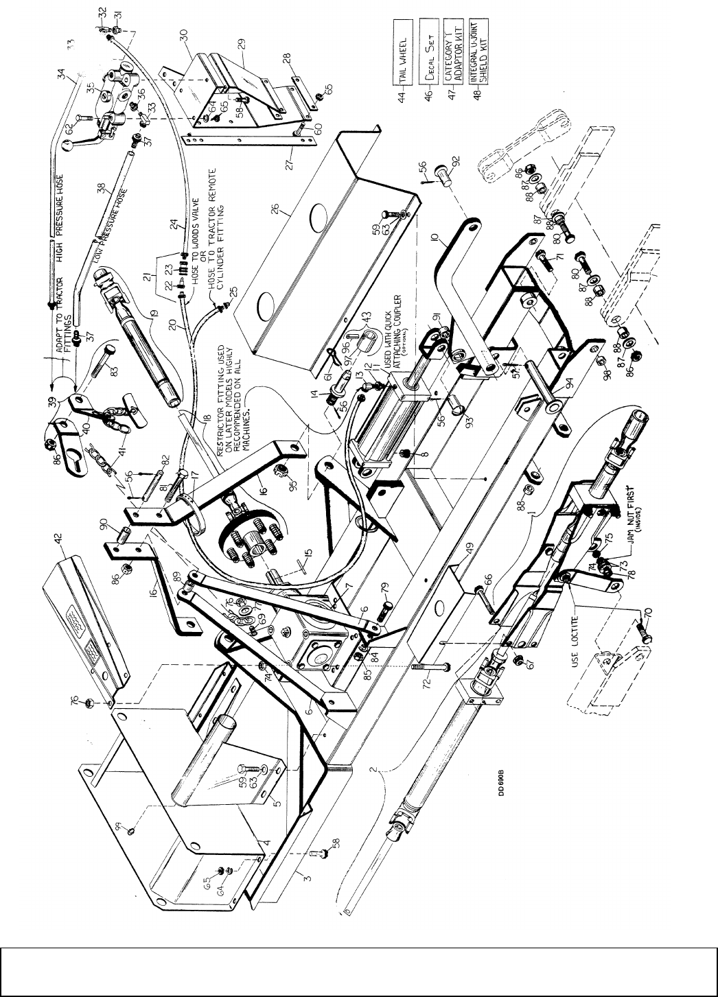
36 Parts
29977 (Rev. 1/23/2009)
CENTER SECTION ASSEMBLY

Parts 37
29977 (Rev. 1/23/2009)
CENTER SECTION ASSEMBLY
HARDWARE
REF PART QTY DESCRIPTION
1 ----- 1 Outer side drive assembly (pg 40)
2 ----- 1 Inner side drive assembly (pg 40)
3 9697 1 540 RPM Center frame (includes
gearbox and shields) -or-
3 8427 1 1000 RPM Center frame (includes
gearbox and shields)
4 29476 1 Counterweight box (empty) -or-
4 29475 1 Counterweight box (filled w/400 lbs)
5 25705 1 Drive shaft shield
6 25771 2 A-Frame brace bar
7 25731 1 540 RPM 1:1 Gearbox (pg 42)-or-
7 33315 1 1000 RPM 1.5:1 Gearbox (pg 42)
8 24767 1 1/2 NPT Check valve assembly
10 25770 1 Lift arm assembly
11 ----- 1 3-1/2 x 8 Hyd cylinder (pg 46)
12 11893 1 1/2 x 1/4 Pipe reducing bushing
13 10290 1 1/4 x 1/4 x 90° Elbow w/1/16 restrictor
14 14012 2 Category 2 hitch pin, 1-1/8 drilled
15 7142 * 2 1/4 x 1/4 x 2 Key
16 24789 2 A-Frame half
17 8641 2 Rubber binding strap
18 25769 1 Slip clutch U-joint and sq shaft (pg 44)
19 9476 1 540 RPM Tubular shaft & QD yoke
11-1/2" (standard) (pg 43) -or-
19 7378 1 540 RPM Tubular shaft & QD yoke
18-1/4" (long) (pg 43) -or-
19 33318 1 1000 RPM Tubular shaft & QD yoke
11-1/2" (standard) (pg 43) -or-
19 33321 1 1000 RPM Tubular shaft & QD yoke
18-1/4" (long) (pg 43)
20 12422 1 1/4 x 90" Hydraulic hose and fitting
21 8575 1 1/4 Quick disconnect coupler
22 8577 1 1/4 Quick disconnect nose assembly
23 8576 1 1/4 Quick disconnect body assembly
24 8107 1 1/4 1-Wire x 36" hydraulic hose
25 11893 * 2 1/2 x 1/4 Pipe reducing bushing
26 25725 1 Cylinder and drive shield
27 11823 1 Fender valve mounting brace
28 11824 2 Valve bracket reinforcement
29 11819 1 Bottom fender valve bracket
30 11820 1 Upper fender valve bracket assembly
31 10802 * 1 3/8 x 1/2 Pipe reducing bushing, str
32 8151 1 3/8M x 1/4F 90° Swivel street elbow
33 11814 2 1/2M x 3/8 F 90° Swivel elbow
34 11825 1 3/8 1-Wire x 60" hose and fitting
35 12457 1 1-Spool, 3-way valve (pg 48)
36 11815 * 2 3/4 x 1/2 Pipe reducing bushing
37 11816 2 1/2 x 3/8 Hydraulic hose coupler
38 11826 1 1/2 LP x 70" Hydraulic hose
39 10521 1 Check chains w/hardware (optional)
40 7906 2 Lower check chain bracket
41 18048 2 3/8 Chain, 32-link & check lug
42 23489 1 Gearbox shield
43 24845 1 Quick coupler bushing kit (optional)
44 12435 1 Tailwheel asy w/lam tire (pg 51) -or-
44 13860 1 Tailwheel w/pneumatic tire (pg 49)
46 12364 1 Complete decal set
47 7112 1 Cat 2 hitch bushing adapter kit (bush-
ings only for Cat 1 pins) -or-
47 13010 1 Cat 2 hitch mounting pin kit (mounting
pins with 7/8 NF thread) -or-
47 23101 1 Cat 1 hitch mounting pin kit (3/4 NF
thread pins with 1-1/8 sleeves)
48 ----- 1 Integral U-joint shield kit (pg 45)
49 26639 1 Inner drive shield
REF PART DESCRIPTION
55 1266 * 3/16 x 1-1/2 Cotter pin
56 1285 * 1/4 x 1-1/2 Cotter pin
57 923 * 1/4 x 1-3/4 Cotter pin
58 839 * 3/8 NC x 1 HHCS GR5
59 12400 3/8 NC x 1" Sheet metal screw
60 1017 * 3/8 NC x 1-1/4 HHCS
61 3282 3/8 x 2-1/4 Lynch pin
62 2290 * 3/8 NC x 2-1/2 HHCS GR5
63 565 * 3/8 Standard flat washer
64 838 * 3/8 Standard lock washer
65 835 * 3/8 NC Hex nut, plated
66 23479 1/2 x 5 HHCS GR5
67 11900 1/2 NC Flanged hex lock nut
68 4097 5/8 x 1-1/2 Clevis pin
69 902 * 5/8 NC x 2 HHCS HT
70 12274 * 5/8 NC x 2-1/4 HHCS HT
71 23141 5/8 NC x 3-1/2 HHCS HT
72 11043 5/8 NC x 7-1/2 HHCS HT
73 10635 5/8 x 1-3/4 x 14 GA Cup washer
74 1598 * 5/8 NC Hex jam nut
75 230 * 5/8 NC Hex nut
76 6239 * 5/8 NC Hex lock nut
77 3632 * 5/8 Standard SAE flat washer
78 484 5/8 ID x 1" OD x 7/16 HT Sleeve
79 735 * 3/4 NC x 2 HHCS
80 14334 3/4 NC x 3 HHCS
81 12558 3/4 NC x 4-1/2 HHCS HT
82 8325 3/4 x 4-27/32 Clevis pin
83 2377 3/4 NC x 6 HHCS HT
84 2522 * 3/4 Standard lock washer
85 1450 * 3/4 NC Hex nut
86 2371 * 3/4 NC Hex lock nut
87 1257 * 3/4 Standard flat washer
88 10083 3/4 x 1-1/8 x 5/8 HT Bushing
89 25778 3/4 x 1-1/4 x 1-5/16 Sleeve
90 7372 25/32 x 1 x 2 Sleeve
91 12270 1 x 1-1/4 x 1 Sleeve HT
92 8341 1 x 2-1/2 Clevis pin HT
93 1631 1 x 3-5/8 Clevis pin
94 8359 1-1/8 x 7 HDD Clevis pin
95 14153 1-1/8 NF Slotted hex nut
96 11606 3/8 x 1-1/2 Spirol pin
97 24795 1-1/8 x 1-7/16 x 2-3/4 Sleeve
98 25723 3/4 x 1-1/8 x 1/2 HT Bushing
99 195 * 1/8 Straight pipe thread grease fitting
* Obtain locally, standard hardware
REF PART QTY DESCRIPTION
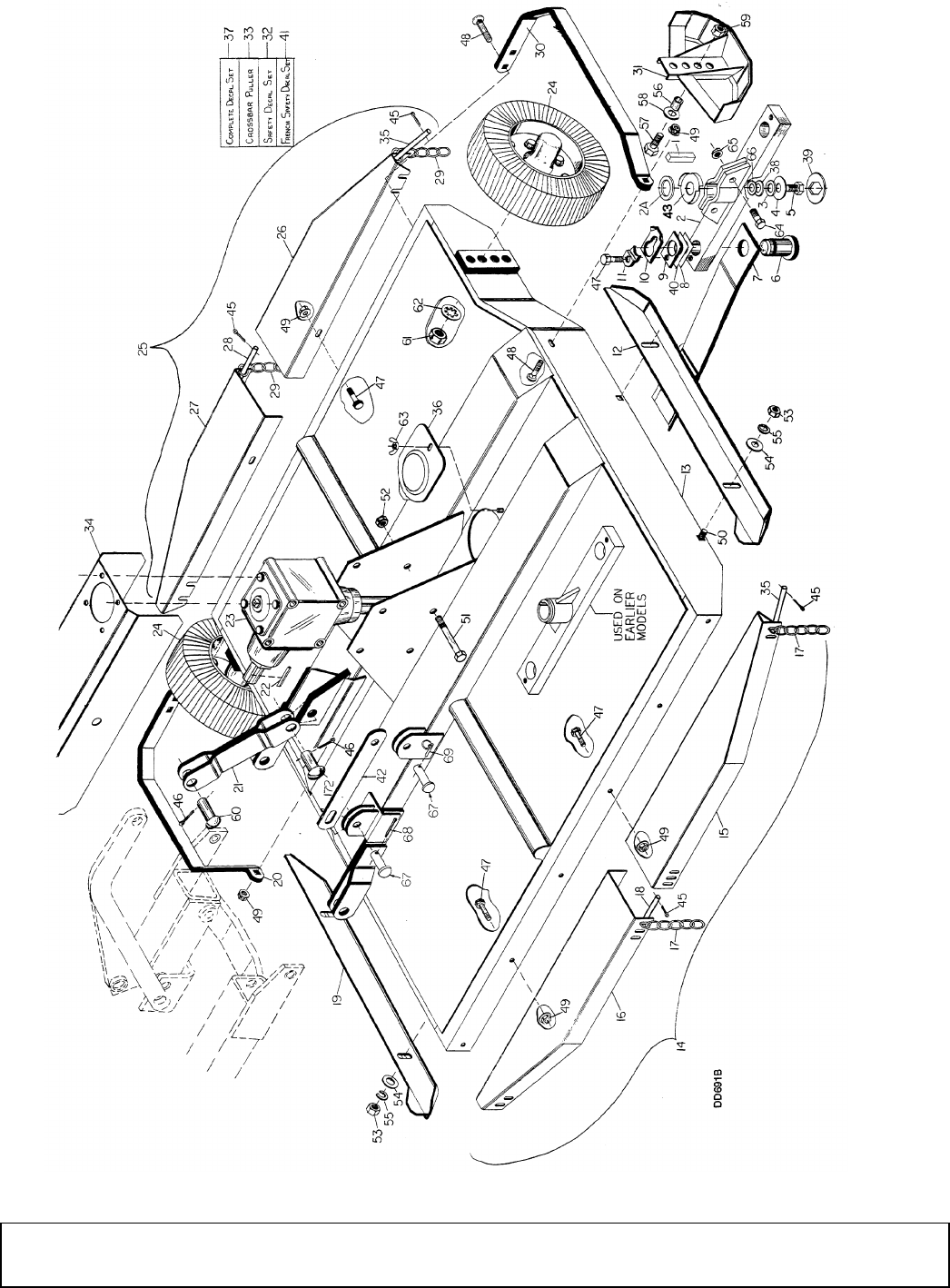
38 Parts
29977 (Rev. 1/23/2009)
CUTTER HEAD SECTION ASSEMBLY

Parts 39
29977 (Rev. 1/23/2009)
CUTTER HEAD SECTION ASSEMBLY
HARDWARE
REF PART QTY DESCRIPTION
1 11041 * 1 3/8 x 3/8 x 2-7/8 Key
2 29269 1 1-5/8 Clamp crossbar (incl. #2A)
2A 29272 1 1-5/8 x 2-1/4 x 7 GA Washer
3 11204 A/R 13/16 x .010 Shim washer
4 7828 1 3/4 x 2-1/2 x 1/4 Washer HT
5 4616 1 3/4 NC x 1-1/2 HHCS GR5
6 32602 2 1-1/2 Blade pin - special
7 24771KT 2 S105 24" Suction type general pur-
pose blade -or-
7 17190KT 2 S105 24" Double-edge flat blade for
brush -or-
7 8820KT 2 S106 30" Suction type general pur-
pose blade -or-
7 8830KT 2 S106 30" Double-edge flat blade for
brush
8 10520 2 18 GA 1-1/2 Blade pin shim
9 5523 2 3/16 Spacer
10 32603 2 Keyhole plate - special
11 32604 2 Blade pin lock clip - special
12 1014151 1 Right rear skid assembly (used on
S105-3 and early S106-3) -or-
12 22670 1 Rear skid assembly (used on S105-3
and early S106-3)
13 9695 1 S105-3 Frame (including gearbox,
skids & crossbar) -or-
13 9696 1 S106-3 Frame (including gearbox,
skids & crossbar)
14 26976 1 S105 Rear chain shield bundle -or-
14 26983 1 S106 Rear chain shield bundle
15 26974 1 S105 Right rear chain plate -or-
15 26986 1 S106 Right rear chain plate
16 26975 1 S105 Left chain plate -or-
16 26987 1 S106 Left chain plate
17 5498 52 S105 5/16 Chain, 6-link -or-
17 5498 60 S106 5/16 Chain, 6 link
18 23733 2 S105 3/8 x 17-1/2, 14-chain -or-
18 10150 2 S106 3/8 x 22-1/4 Long pin
19 1014151 1 Left rear skid assembly (used on
S105-3 & early S106-3) -or-
19 22670 1 Rear skid (used on S106-3 only)
20 25773 1 Left wheel guard
21 12412 1 Clevis lift link
22 7142 * 2 1/4 x 1/4 x 2 Key
23 ----- 1 Cutter head gearbox (see pg 41)
24 ----- 2 Wheel and hub (see pg 52)
25 26967 1 S105 Front chain shielding bundle
-or-
25 26977 1 S106 Front chain shielding bundle
26 26970 1 S105 Right front chain plate -or-
26 26980 1 S106 Right front chain plate
27 26971 1 S105 Left front chain plate -or-
27 26981 1 S106 Left front chain plate
28 3783 2 S105 3/8 x 14-3/4 Pin -or-
28 26982 2 S106 3/8 x 21-1/2 Pin, 17-chain
29 5498 48 S105 5/16 Chain, 6-link -or-
29 5498 58 S106 5/16 Chain, 6-link
30 25772 1 Right wheel guard
31 25800 2 Front corner skid
32 31895 1 English safety decal set
33 8811 1 Crossbar puller (see pg 53)
34 26651 1 S105 Side drive shield -or-
34 26652 1 S106 Side drive shield
35 3783 4 3/8 x 14-3/4 Pin
36 3444 1 Access hole cover assembly
37 12364 1 Complete English decal set
38 11036 1 3/4 x 1-1/2 x 18 GA Shim washer
39 5791 1 1-1/8 Washer with hex hole
40 13946 1 20 GA, 1-1/2 Blade pin shim
41 51895 1 French safety decal set
42 19668 1 Lock-up bar 16.00 (on S/N 8499 &
below, use #25774 bar & #11697
chain)
43 15831 1 Anti-wrap washer, 3.68 dia
REF PART DESCRIPTION
45 1256 * 3/16 x 1 Cotter pin
46 1285 * 1/4 x 1-1/2 Cotter pin
47 6100 * 1/2 NC x 1-1/4 HHCS GR5
48 12735 1/2 NC x 1-3/4 Carriage bolt HT
49 11900 * 1/2 NC Flanged hex lock nut
50 5607 * 5/8 NC x 1-1/2 Carriage bolt
51 11043 5/8 NC x 7-1/2 HHCS GR5
52 6239 * 5/8 NC Hex lock nut
53 230 * 5/8 NC Hex nut
54 692 * 5/8 Standard flat washer
55 1286 * 5/8 Heavy lock washer
56 25806 3/4 x 1 x 1-7/8 Sleeve
57 13759 3/4 NC x 2-1/4 HHCS HT
58 1257 * 3/4 Standard flat washer
59 2371 * 3/4 NC Hex lock nut
60 8341 1 x 2-1/2 Clevis pin HT
61 3626 1-14 UNS Hex nut
62 3689 * 1" Standard lock washer
63 1287 * 3/8 NC Wing nut
64 3699 * 1/2 NC x 2 HHCS GR5
65 11900 * 1/2 NC Flanged hex lock nut
66 19080 .81 x 1.57 x .07 Washer
67 4097 5/8 x 1-1/2 Clevis pin
68 1266 * 3/16 x 1-1/2 Cotter pin
69 22411 3/16 x 1 Klik pin
* Obtain locally, standard hardware
REF PART QTY DESCRIPTION
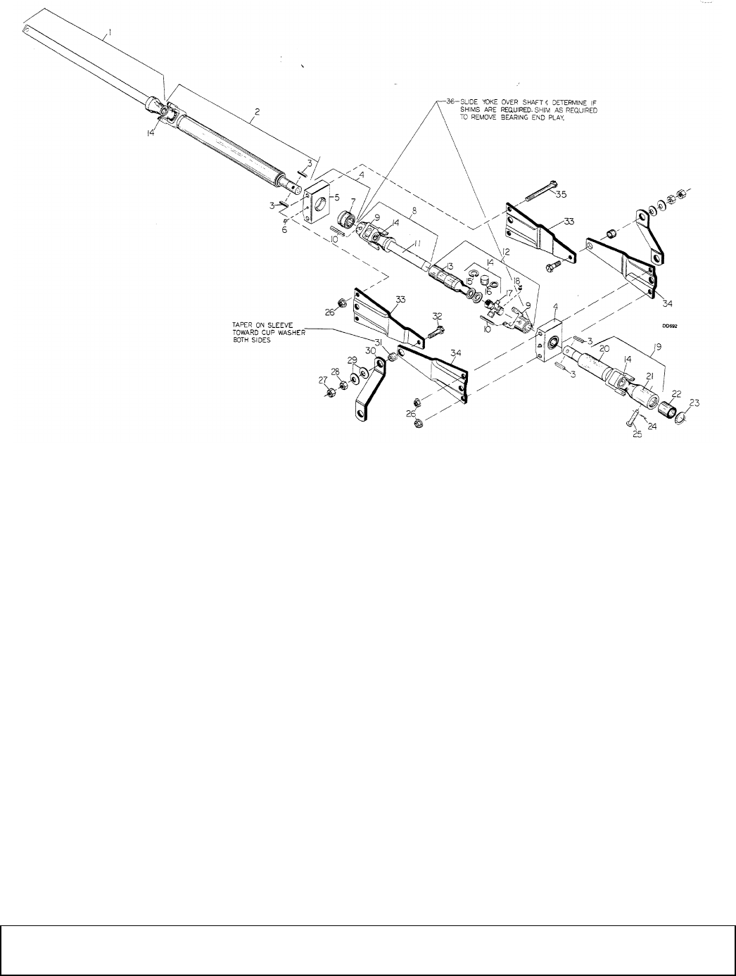
40 Parts
29977 (Rev. 1/23/2009)
TUBULAR SIDE DRIVE ASSEMBLY
REF PART QTY DESCRIPTION
1 13964 1 1-1/2 Square shaft 35R yoke 28"
2 25766 1 Yoke, tube & bearing stub
3 3886 * 4 1/4 x 1/4 x 1-1/4 Key
4 23484 2 Side drive bearing block assembly
5 23385 2 Side drive bearing block
6 195 * 2 Straight 1/8 pipe thread grease fitting
7 23450 2 1-1/2 Double bearing repair kit
(includes item 36)
8 23470 1 Center slip shaft assembly
9 23471 2 1.5 Bore keyed yoke 35R
10 7276 2 7/16 x 2-1/2 Spirol pin
11 23472 1 Center slip shaft with yoke
12 23474 1 Inner tube and yoke
13 23475 1 Inner asy tube & yoke, 1-1/2 sq.
sleeve
14 110 3 U-joint repair kit 35R
15 N/S 12 Snap ring
16 N/S 12 Needle cup and cork washer
17 N/S 3 Center cross
18 N/S 3 Grease fitting
19 23480 1 S105 Drive shaft & shear yoke 35R
-or-
19 23498 1 S106 Drive shaft & shear yoke 35R
20 23481 1 S105 Special yoke with bearing stub
35R, 10-11/16" long -or-
20 23499 1 S106 Yoke, tube and bearing stub,
35R 16-11/16" long
21 4655 1 Yoke with shear pin sleeve
22 4659 1 Inner shear sleeve
23 5278 1 .048 x 2-1/4 Snap ring
24 3597 * 2 1/8 x 1 Cotter pin
25 11895 1 7/16 x 3 Hard shear pin
26 11900 4 1/2 NC Flanged hex lock nut
27 230 * 2 5/8 NC Hex nut
28 1598 * 2 5/8 NC Hex jam nut
29 10635 4 5/8 x 1-3/4 x 14 GA Cup washer
30 12312 2 Drive joint support arm
31 12313 2 5/8 x 1 x 13/16 HT Sleeve
32 12274 * 2 5/8 NC x 2-1/4 HHCS HT
33 23469 2 Offset side plate
34 23477 2 Flat side plate
35 23479 4 1/2 NC x 5 HHCS GR5
36 30473 - 1-1/2 x 2 x 28 GA Shim (as needed)
* Standard hardware, obtain locally
N/S Not sold separately
REF PART QTY DESCRIPTION
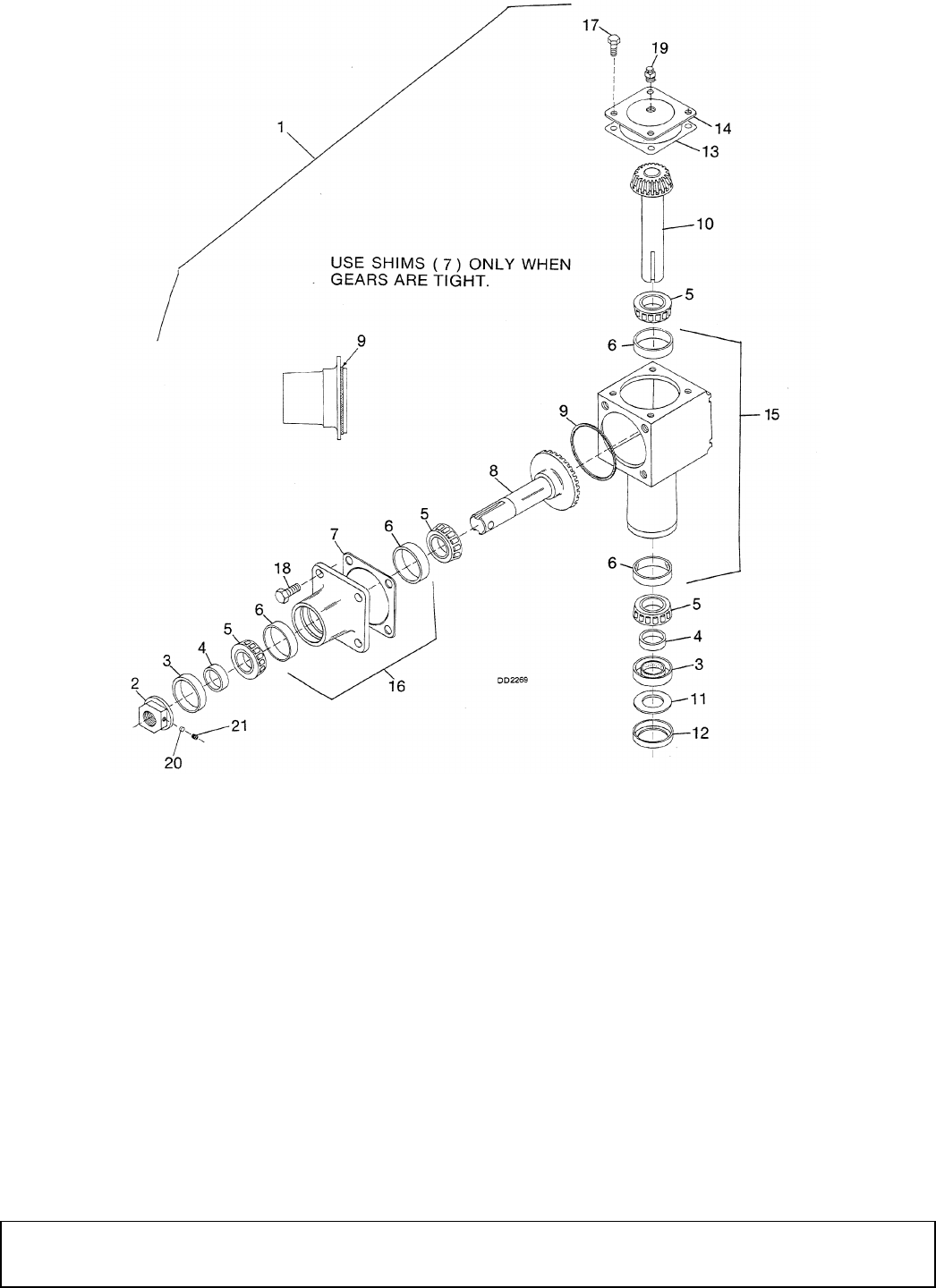
Parts 41
29977 (Rev. 1/23/2009)
CUTTER HEAD GEARBOX ASSEMBLY
REF PART QTY DESCRIPTION
1 11155 1 S105 1.35:1 Gearbox complete -or-
1 11050 1 S106 1:1 Gearbox complete
2 11007 1 1-5/8 Flanged nut
3 11010 2 Seal for 2-1/8 shaft
4 11054 2 1-5/8 x 2-1/8 x 5/8 Sleeve
5 11114 4 Bearing cone
6 11115 4 Bearing cup
7 11209 1 .010 Gearbox gasket (used only if
more backlash is required)
8 11160 1 S105 Horizontal gear and shaft asy
(23-tooth) -or-
8 11057 1 S106 Horizontal gear and shaft asy
(17-tooth)
9 10055 1 1/8 SQ x 5-1/4 OD O-ring
10 11158 1 S105 Vertical gear & shaft asy (17-
tooth) -or-
10 11053 1 S106 Vertical gear & shaft asy (17-
tooth)
11 11056 1 1-5/8 ID x 3 OD x 10 GA Flat washer
(used alone) -or-
11 25367 1 1-5/8 ID x 2-3/4 OD x 10 GA Flat
washer (used with item 12)
12 25365 1 Gearbox washer retainer
13 11442 1 .062 x 4-1/2 ID x 5 Gasket
14 11005 1 Gearbox cover with plugs
15 11062 1 Housing with cups
16 11063 1 Horizontal housing with cups
17 1686 * 4 3/8 NC x 3/4 HHCS GR5
18 7832 * 4 5/8 NC x 1-1/2 HHCS GR5
19 23057 1 1/2 NPTF Vented pipe plug
20 7127 1 5/16 x 5/32 Dowel plug
21 7269 1 3/8 NC x 3/8 Flat point socket set
screw
22 23675 1 1" Breather vent pipe plug (not shown)
* Standard hardware, obtain locally
REF PART QTY DESCRIPTION
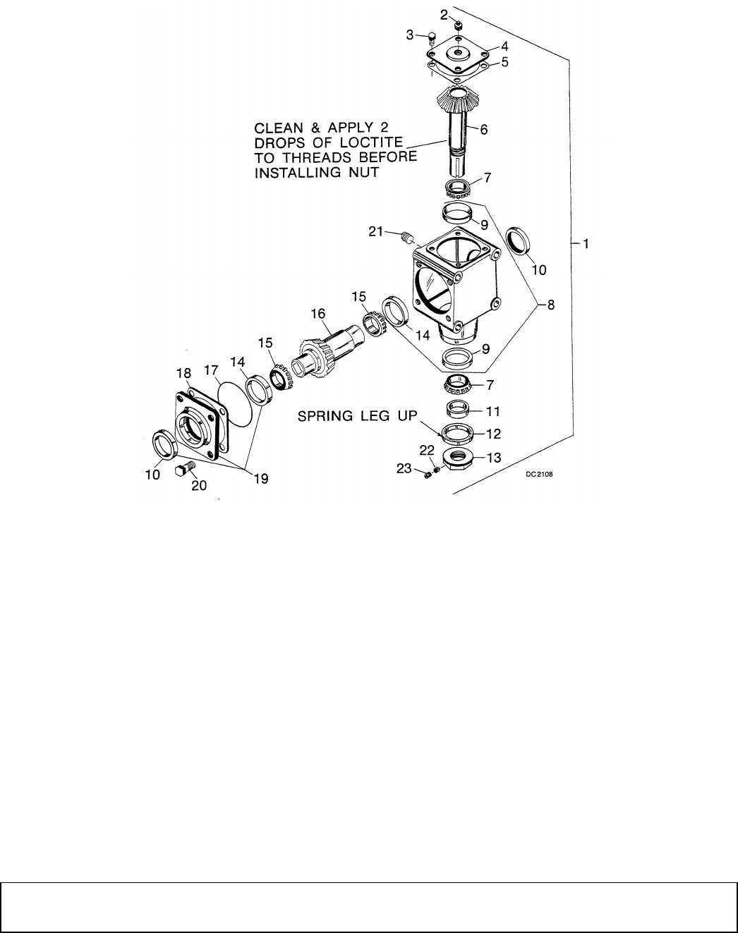
42 Parts
29977 (Rev. 1/23/2009)
INPUT GEARBOX ASSEMBLY
REF PART QTY DESCRIPTION
1 25731 1 540 RPM Gearbox 1:1 -or-
1 33315 1 1000 RPM Gearbox 1.5:1
2 4510 * 1 1/2 Pipe plug
3 1686 * 4 3/8 NC x 3/4 HHCS GR5
4 23051 1 Gearbox cover
5 11442 1 .062 x 4-1/2 ID x 5 Gasket
6 18088 1 540 RPM Input gear shaft asy 1.5 -or-
6 33316 1 1000 RPM Input gear & shaft asy
7 11114 2 Bearing cone LM501349
8 25733 1 Gearbox housing with cups
9 11115 2 Bearing cup LM501310
10 11553 2 Seal for 2.25 shaft double lip
11 11054 1 1-5/8 x 2-1/8 x 5/8 Sleeve
12 11010 1 Seal for 2-1/8 shaft
13 11007 1 1-5/8 Flanged nut
14 11555 2 Bearing cup, 3.81 OD
15 11556 2 Bearing cone, 2.25 ID
16 17069 1 540 RPM 1:1 Horizontal gear and
shaft -or-
16 33317 1 1000 RPM Horizontal gear and shaft
17 10055 1 1/8 Square x 5-1/4 OD O-ring
18 11209 1 .010 Gearbox gasket -or-
18 17215 1 .005 Gearbox gasket
19 17073 1 Wing bearing cap, cup & seal
20 7832 * 4 5/8 NC x 1-1/2 HHCS GR5
21 23675 - 1" Breather vent pipe plug
22 7127 - 5/16 x 5/32 Dowel plug
23 7269 - 3/8 NC x 3/8 Flat point socket set
screw
* Standard hardware, obtain locally
REF PART QTY DESCRIPTION
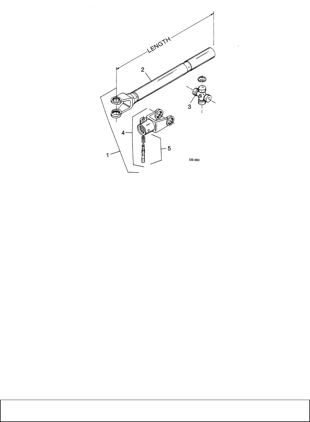
Parts 43
29977 (Rev. 1/23/2009)
FRONT HALF OF 2-JOINT DRIVE 35R
STANDARD DRIVE
LONG DRIVE
REF 540 RPM 1000 RPM QTY DESCRIPTION
1 9476 33318 1 Tubular shaft & joint 35R, 11-1/2"
2 23495 23495 1 Tubular 11-1/2" shaft & yoke 35R
3 110 110 1 Universal joint repair kit 35R
4 115 10938 1 Quick detach U-joint yoke 35R
5 117 117 1 Lock pin & spring
REF 540 RPM 1000 RPM QTY DESCRIPTION
1 7378 33321 1 Tubular shaft & joint 35R, 18-1/4"
2 7379 7379 1 Tubular shaft & yoke, 18-1/4" long, 35R
3 110 110 1 Universal joint repair kit 35R
4 115 10938 1 Quick detach U-joint yoke 35R
5 117 117 1 Lock pin & spring
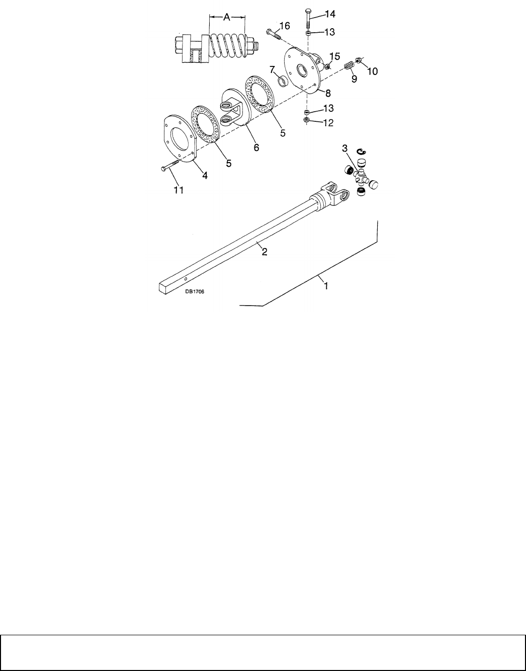
44 Parts
29977 (Rev. 1/23/2009)
SLIP CLUTCH ASSEMBLY
REF PART QTY DESCRIPTION
1 25769 1 6S Clutch 1.5B 35R x 14-1/2" Square
shaft
2 23488 1 1-3/16 Square shaft with yoke 35R,
14-1/2"
3 110 1 U-Joint repair kit 35R
4 13931 1 6S Clutch back-up plate
5 19459 2 Friction disc, 4 x 6.15
6 13928 1 6S Clutch yoke and plate 35R
7 11576 1 1-7/16 x 1-5/8 x 9/16 Bronze bushing
8 13933 1 6S Clutch hub, 1-1/2 with bushing
9 29687 6 2 GA x 2-3/16 Compression spring
10 12914 6 3/8 NC Wide flanged lock nut
11 13927 6 3/8 NC x 3-3/4 HHCS GR5
12 13921 * 1 7/16 NC Hex lock nut
13 ----- - (Not used on this installation)
14 6048 * 1 7/16 NC x 3-1/2 HHCS GR5
15 6239 * 1 5/8 NC Hex lock nut
16 23141 1 5/8 NC x 3-1/2 HHCS GR5
17 7283 6 Compression spring repair kit
(includes items 9-11)
* Standard hardware, obtain locally
REF PART QTY DESCRIPTION
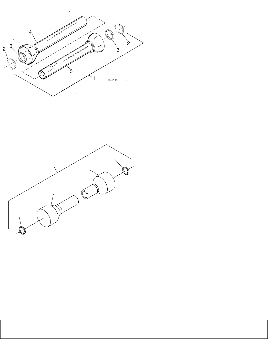
Parts 45
29977 (Rev. 1/23/2009)
INTEGRAL U-JOINT SHIELDING (USED ON EARLIER MACHINES)
U-JOINT SHIELDING (PLASTIC) (USED ON LATER MACHINES)
STANDARD DRIVE
LONG DRIVE
REF PART QTY DESCRIPTION
1 24441 1 Integral U-joint shield kit, standard
2 7398 2 Integral shield snap ring
3 4677 2 Nylon rectangular groove bearing 35R
4 24443 1 U-Joint outer shield 10"
5 24442 1 U-Joint inner shield 9"
REF PART QTY DESCRIPTION
1 24444 1 Integral shield kit
2 7398 2 Integral shield snap ring
3 4677 2 Nylon rectangular groove bearing 35R
4 24443 1 U-Joint outer shield 10"
5 4919 1 Inner shield 35R
CD6906
2
4
4
3
1
NOTE: Shield halves must be cut to length. See
Assembly Section page 29 for procedures.
REF PART QTY DESCRIPTION
1 1007870 1 Shield kit, plastic
2 1007871 1 Outer shield, 3.00 x 2.81 x 38.0
3 1007872 1 Inner shield, 2.75 x 2.56 x 43.3
4 15740 2 Shield bearing
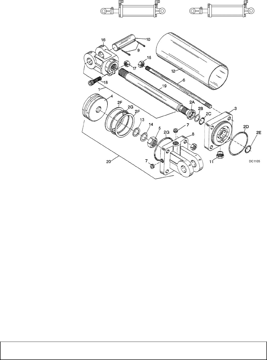
46 Parts
29977 (Rev. 1/23/2009)
3-1/2" BORE & 8" STROKE HYDRAULIC CYLINDER
Woods purchases hydraulic cylinders from various manufac-
turers. These cylinders have small dimensional differences.
Each cylinder has a brief identification note. Read each note
and find the dimensions or identification features for your cyl-
inder. After establishing identification, use the corresponding
parts list.
Lantex or Hydroline - Stamped or cast on butt housing (item
8) or rod end housing (item 3).
Prince - Cylinder barrel (12) length is 10-5/8" long. Diameter
of cylinder rod (19) is 1-1/8". Cylinder was sold prior to 1971.
To convert a 10475 cylinder to a
18725 cylinder: Remove the rod hex
nuts (15) and tie rods (6). Rotate rod
end housing 180° so both ports are in
line. Reinstall tie rods and hex nuts.
Torque to 55 lbs-ft.
To convert a 18725 cylinder to a
10475 cylinder: Remove tie rod hex
nuts (15) and tie rods (6). Rotate rod
end housing 180° so ports are on
opposite sides. Reinstall tie rods and
hex nuts. Torque to 55 lbs-ft.
#10475 is a single-acting cylinder. Hoses
and fittings are installed in one port and
vent plug is installed in another port.
#18725 is a double-acting cylinder.
Hoses and fittings are installed in both
ports. Vent plug is not required.
REF PART QTY DESCRIPTION
2 23540 1 Seal kit (includes 2A - 2G)
2A ----- 1 1-1/4 ID Wiper seal
2B ----- 1 Rod back-up ring
2C ----- 2 1-1/4 ID O-ring
2D ----- 2 3/16 x 3-1/2 OD O-ring
2E ----- 1 3/32 x 3/4 OD O-ring
2F ----- 2 3-1/2 OD Back-up washer
2G ----- 1 Piston seal kit
3 26338 1 Rod end housing
4 25497 1 Piston
5 25496 1 1 - 14 UNS Jam nut
6 ----- 4 Tie rod
7 11893 * 1 1/2 x 1/4 Pipe reducer bushing
8 25494 1 Cylinder butt end
9 923 * 4 1/4 x 1-3/4 Cotter pin
10 1631 2 1 x 3-5/8 Clevis pin
11 11975 1 1/2 NPT Vent plug -or-
11 23547 1 1/4 NPT Vent plug
12 ----- 1 Cylinder barrel
15 4391 8 1/2 NF Hex jam nut
16 25661 1 Cylinder rod clevis
17 6698 * 1 3/8 NC Hex lock nut
18 23550 * 1 3/8 NC x 1-1/2 Socket head cap screw
19 26343 1 Cylinder rod
20 10475 1 Hyd cylinder complete (single) -or-
20 18725 1 Hyd cylinder complete (double)
21 4510 * 1 1/2 Pipe plug
REF PART QTY DESCRIPTION
1 ----- 1 Piston rod asy (incl.13, 14, 16-19)
2 23540 1 Seal kit (includes 2A - 2G)
2A ----- 1 1-1/8 ID Wiper seal
2B ----- 1 1-1/8 ID Leather back-up washer
2C ----- 2 1-1/8 ID O-ring
2D ----- 2 3/16 x 3-1/2 OD O-ring
2E ----- 1 3/32 x 3/4 OD O-ring
REF PART QTY DESCRIPTION

Parts 47
29977 (Rev. 1/23/2009)
Prince - Cylinder barrel (12) length is 10-1/6" long. Diameter
of cylinder rod (19) is 1-1/8".
Prince - Cylinder barrel (12) length is 10-1/2" long. Diameter
of cylinder rod (19) is 1-1/4".
Lantex or Hydroline - Stamped or cast on butt housing (8) or
rod end housing (3).
2F ----- 2 3-1/2 OD Back-up washer
2G ----- 1 3/16 x 3-1/2 OD O-ring
3 ----- 1 Rod end housing
4 ----- 1 Piston
5 3969 1 3/4 NF Hex nut
6 ----- N/A Tie rod
7 11893 * 1 1/2 x 1/4 Pipe reducer bushing
8 ----- 1 Cylinder butt end
9 923 * 4 1/4 x 1-3/4 Cotter pin
10 1631 2 1 x 3-5/8 Clevis pin
11 11975 1 1/2 NPT Vent plug
12 ----- 1 Cylinder barrel
13 ----- 1 7/8 ID Thread seal
14 ----- 1 3/4 ID Flat steel washer
15 1093 8 1/2 NC Heavy hex nut
16 ----- 1 Cylinder rod clevis
17 6778 * 1 5/16 NC Hex lock nut
18 6250 * 1 5/16 NC x 1-1/4 Cap screw GR5
19 ----- 1 Cylinder rod
20 10475 1 Hyd cylinder complete (single) -or-
20 18725 1 Hyd cylinder complete (double)
21 ----- - 1/2 Pipe plug
REF PART QTY DESCRIPTION
1 ----- 1 Piston rod asy (includes 16-19)
2 23540 1 Seal kit (includes 2A - 2G)
2A ----- 1 1-1/8 ID Wiper seal
2B ----- 1 1-1/8 ID Leather back-up washer
2C ----- 2 1-1/8 ID O-ring
2D ----- 2 3/16 x 3-1/2 OD O-ring
2E ----- 1 1/16 x 3/4 ID O-ring
2F ----- 2 3-1/2 OD Back-up washer
2G ----- 1 3/16 x 3-1/2 OD O-ring
3 ----- 1 Rod end housing
4 23354 1 Piston
5 3969 1 3/4 NF Hex nut
6 23355 4 Tie rod
7 11893 * 1 1/2 x 1/4 Pipe reducer bushing
8 ----- 1 Cylinder butt end
9 923 * 4 1/4 x 1-3/4 Cotter pin
10 1631 2 1 x 3-5/8 Clevis pin
11 11975 1 1/2 NPT Vent plug
12 ----- 1 Cylinder barrel
15 1093 8 1/2 NC Heavy hex nut
16 23358 1 Cylinder rod clevis
17 6778 * 1 5/16 NC Hex lock nut
18 6250 * 1 5/16 NC x 1-1/4 Cap screw GR5
19 23360 1 Cylinder rod
20 10475 1 Hyd cylinder complete (single) -or-
20 18725 1 Hyd cylinder complete (double)
21 4510 * 1 1/2 Pipe plug
REF PART QTY DESCRIPTION
REF PART QTY DESCRIPTION
2 23540 1 Seal kit (includes 2A - 2G)
2A ----- 1 1-1/4 ID Wiper seal
2C ----- 2 1-1/4 ID O-ring
2D ----- 2 3/16 x 3-1/2 OD O-ring
2F ----- 2 3-1/2 OD Back-up washer
3 23543 1 Rod end housing
4 23544 1 Piston
5 21308 1 1" NF Hex nut
6 ----- 4 Tie rod
7 11893 * 1 1/2 x 1/4 Pipe reducer bushing
8 23546 1 Cylinder butt end
9 923 * 4 1/4 x 1-3/4 Cotter pin
10 1631 2 1 x 3-5/8 Clevis pin
11 11975 1 1/2 NPT Vent plug
11 23547 1 1/4 NPT Vent plug
12 ----- 1 Cylinder barrel
15 1093 8 1/2 NC Heavy hex nut
15 4391 8 1/2 NF Hex jam nut
16 23549 1 Cylinder rod clevis
17 6698 * 1 3/8 NC Hex lock nut
18 23550 * 1 3/8 NC x 1-1/2 Socket head cap screw
19 23551 1 Cylinder rod
20 10475 1 Hyd cylinder complete (single) -or-
20 18725 1 Hyd cylinder complete (double)
21 ----- - 1/2 Pipe plug
REF PART QTY DESCRIPTION
2 25485 1 Seal kit (includes 2A - 2G)
2A ----- 1 1-1/8 ID Wiper seal
2C ----- 1 1-1/8 ID O-ring
2D ----- 2 3/16 x 3-1/2 OD O-ring
2E ----- 1 1-1/16 x 3/4 ID O-ring
2G ----- 1 Block "V" packing seal
3 ----- 1 Rod end housing
4 ----- 1 Piston
5 N/A 1 7/8 UNF Hex nut
6 23355 4 Tie rod
7 11893 * 1 1/2 x 1/4 Pipe reducer bushing
8 ----- 1 Cylinder butt end
9 923 * 4 1/4 x 1-3/4 Cotter pin
10 1631 2 1 x 3-5/8 Clevis pin
11 11975 1 1/2 NPT Vent plug
12 27065 1 Cylinder barrel
15 1093 8 1/2 NC Heavy hex nut
16 25661 1 Cylinder rod clevis
17 6698 * 1 3/8 NC Hex lock nut
18 23550 * 1 3/8 NC x 1-1/2 Socket head cap screw
19 ----- 1 Cylinder rod
20 10475 1 Hyd cylinder complete (single) -or-
20 18725 1 Hyd cylinder complete (double)
21 ----- - 1/2 Pipe plug
* Standard hardware, obtain locally
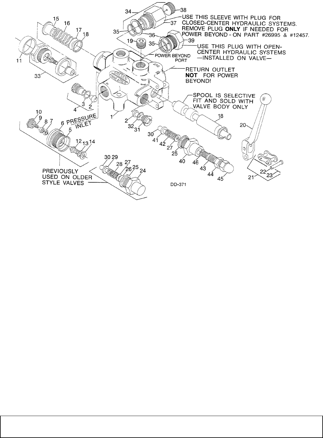
48 Parts
29977 (Rev. 1/23/2009)
1 SPOOL, 3-WAY VALVE (OPTIONAL)
REF PART QTY DESCRIPTION
1 26995 1 1 Spool, 3-way valve w/open center,
complete
2 31097 2 Lift check poppet
3 31087 1 Check plug gasket
4 31098 1 Lift check guide plug (includes 2 & 3)
5 ----- ** - O-Ring gasket
6 ----- ** - Detent housing
7 ----- ** - Detent dog
8 ----- ** - Detent lock follower pin
9 ----- ** - Detent lock spring
10 ----- ** - Detent plug
11 11853 1 Rubber cap for spool end
12 ----- ** - Detent bolt
13 ----- ** - Lock washer
14 ----- ** - Flat washer
15 31072 1 Hat washer
16 31074 1 Spool centering spring
17 31088 1 Flat washer
18 11852 2 V Cup spool seal
19 4510 1 1/2 Pipe plug
20 11850 1 Handle (includes 21)
21 3144 1 #80 Roller chain connector link kit
(includes 22 & 23)
22 11851 1 1/4 x 1-1/4 Clevis pin
23 31066 1 Cotter pin
24 31094 1 Relief cap
25 31077 1 Relief copper gasket
26 31081 1 Relief valve adjustment shim
27 31090 1 Relief valve adjustment washer
28 31076 1 Relief valve spring
29 31096 1 Relief valve poppet follower
30 ----- 1 Relief valve ball
31 31100 1 Relief valve poppet
32 31095 1 Relief valve O-ring
33 23115 1 Detent kit (replaces 5-10 & 12-14)
34 27455 1 Sleeve assembly for power beyond
(includes 35-37)
35 31082 1 Nose seal
36 31101 1 Sleeve seal
37 ----- - Sleeve for power beyond (not sold
separately, order item 34)
38 14434 1 3/4 Pipe plug
39 31103 1 Plug (includes 35 & 36)
40 31078 1 Body
41 31086 1 Spring guide
42 31089 1 Spring
43 31079 1 Adjustment screw
44 31083 1 Adjusting jam nut
45 31084 1 Acorn cap nut
46 31080 1 O-Ring adjusting screw
** These parts no longer sold sepa-
rately. Order complete kit, item 33.
REF PART QTY DESCRIPTION
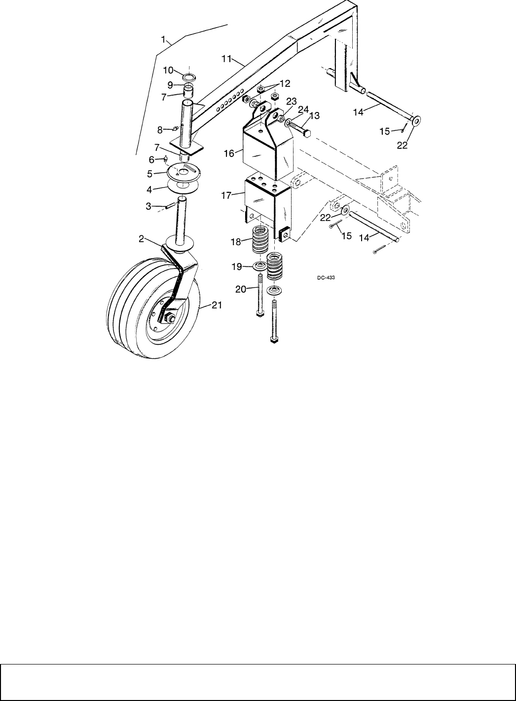
Parts 49
29977 (Rev. 1/23/2009)
PNEUMATIC TAILWHEEL ASSEMBLY
REF PART QTY DESCRIPTION
1 13860 1 Pneumatic tailwheel asy complete
2 14125 1 Tailwheel yoke assembly
3 7276 1 7/16 x 2-1/2 Spirol pin
4 19459 1 Friction disc, 4 x 6.15
5 14135 1 Tailwheel dampener top plate asy
6 195 * 1 Straight 1/8 pipe thread grease fitting
7 11011 2 1-1/2 x 1-5/8 x 1-1/2 Bronze bushing
8 1972 * 1 1/4 - 28 Tapered thread grease fitting
9 12889 1 3/32 x 1-9/16 OD O-ring
10 12881 1 Tailwheel cap washer
11 13861 1 Pneumatic tailwheel arm asy
12 12006 3 5/8 NC Elastic stop nut
13 3097 1 5/8 NC x 4-1/2 HHCS GR5
14 11872 2 3/4 x 11-1/16 Clevis pin
15 1285 * 4 1/4 x 1-1/2 Cotter pin
16 12443 1 Tailwheel attachment guide cup asy
17 12449 1 Tailwheel spring housing asy
18 10260 2 1/2 x 6-1/2 Compression spring
19 12447 2 5/8 x 3 x 7 GA Hat washer
20 11043 2 5/8 NC x 7-1/2 HHCS GR5
21 ----- 1 Wheel, tire and hub (see pg 49)
22 1257 * 4 3/4 Flat washer
23 484 2 5/8 x 1 x 7/16 HT Sleeve
24 692 * 2 5/8 Standard flat washer
* Standard hardware, obtain locally
REF PART QTY DESCRIPTION
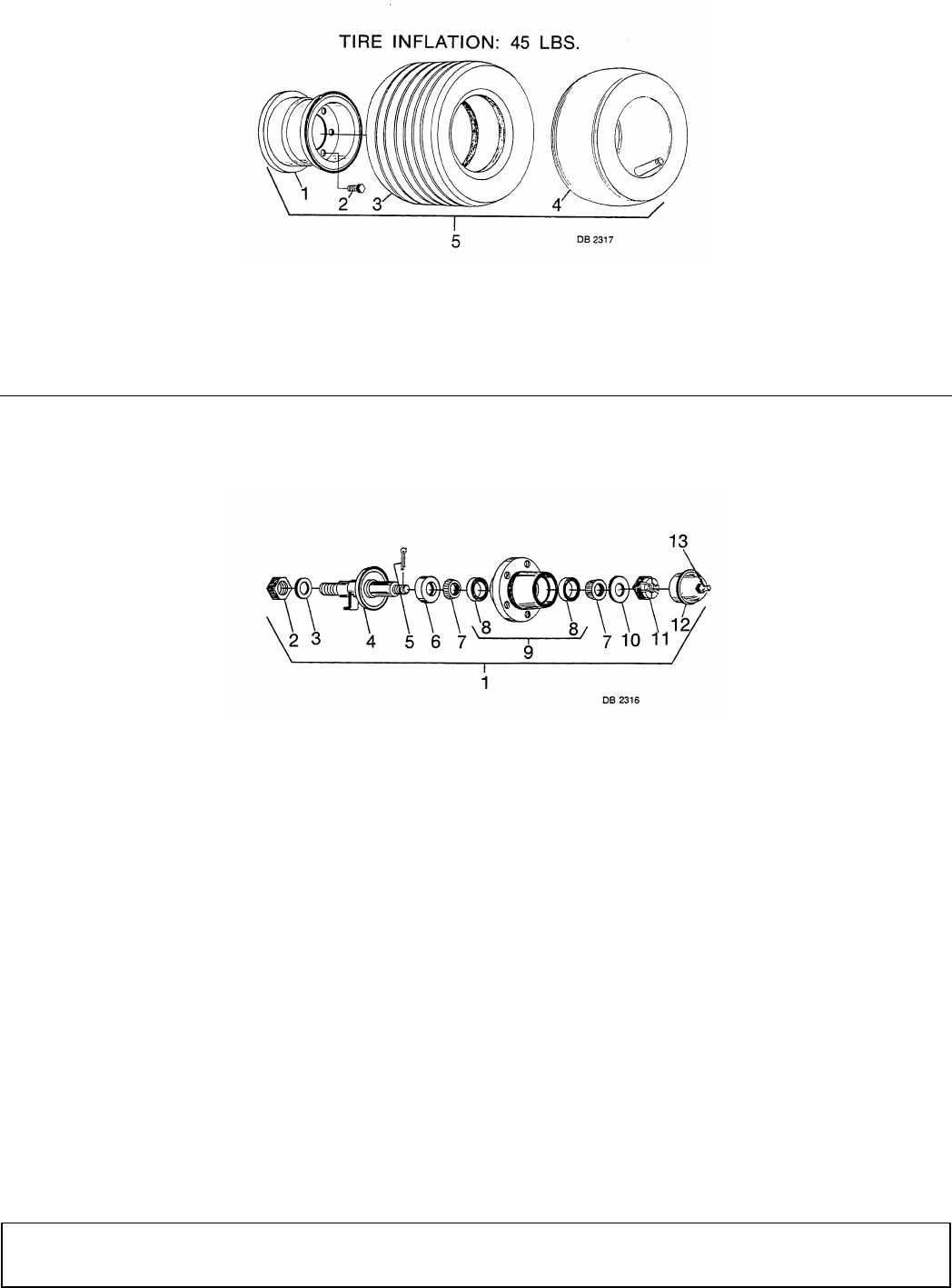
50 Parts
29977 (Rev. 1/23/2009)
PNEUMATIC TIRE ASSEMBLY FOR TAILWHEEL
HUB ASSEMBLY FOR PNEUMATIC TAILWHEEL
REF PART QTY DESCRIPTION
1 ----- 1 Rim for 18 x 9.5 x 8 tire
2 1258 5 1/2 NF x 1-1/8 Wheel bolt
3 ----- 1 18 x 9.5 x 8 6-Ply rib tire
4 ----- 1 18 x 9.5 x 8 Inner tube
5 14255 1 18 x 9.5 x 8 Rib tire and 5-hole
wheel
REF PART QTY DESCRIPTION
REF PART QTY DESCRIPTION
1 14130 1 5-Bolt wheel hub with axle
2 3626 1 1-14 UNS Hex nut
3 3689 * 1 1" Standard lock washer
4 14131 1 Tailwheel axle assembly
5 1266 * 1 3/16 x 1-1/2 Cotter pin
6 314 1 Seal for 1-1/2 shaft
7 2303 2 Bearing cone
8 2305 2 Bearing cup
9 14132 1 5-Bolt wheel hub with cups
10 1257 * 1 3/4 Standard flat washer
11 5849 1 3/4 NF Slotted hex nut
12 14133 1 Hub caps with grease fitting
13 ----- * 1 Straight 1/4 tapered thread grease
fitting (for hub caps)
* Standard hardware, obtain locally
REF PART QTY DESCRIPTION
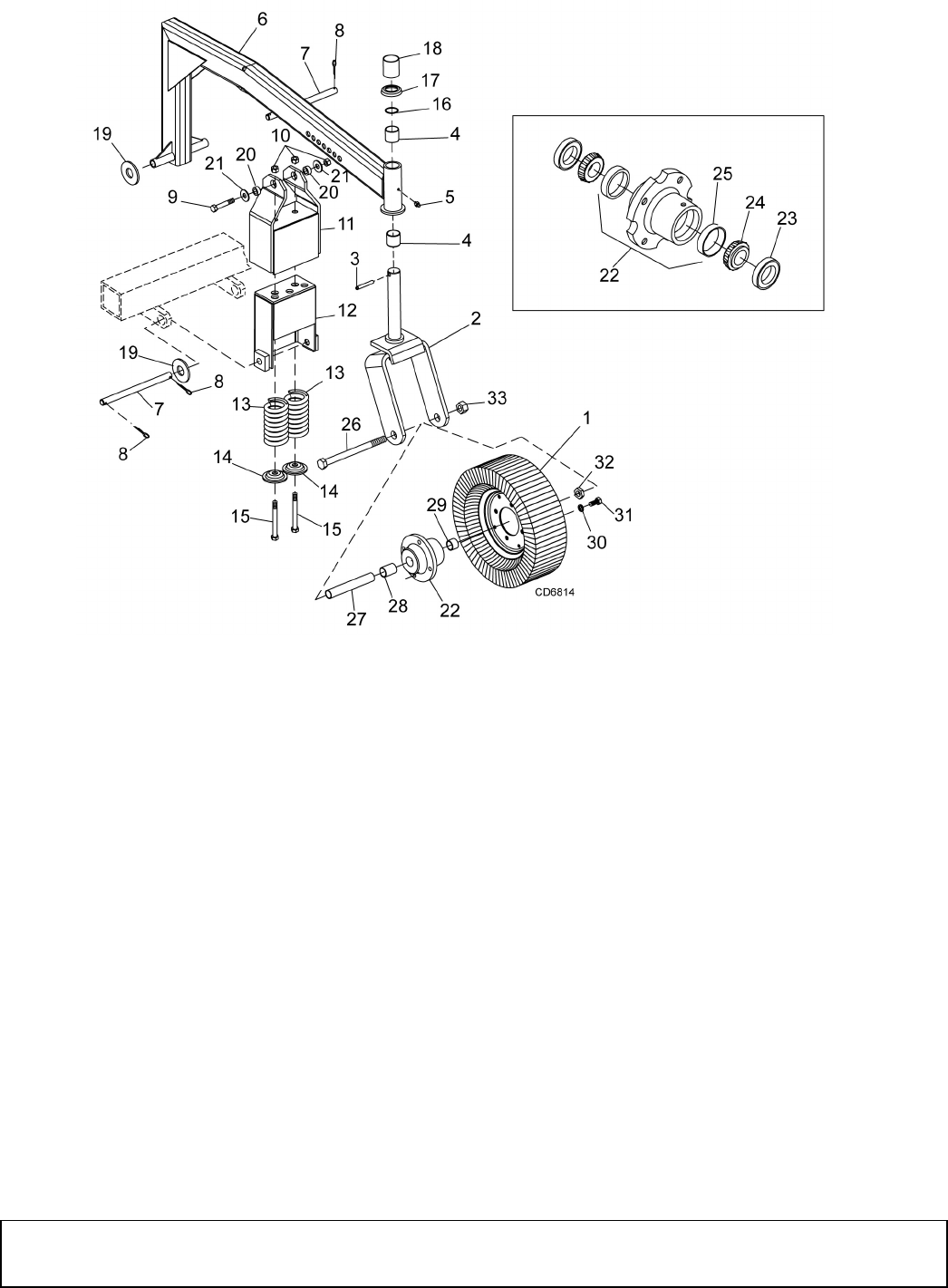
Parts 51
29977 (Rev. 1/23/2009)
TAILWHEEL ASSEMBLY
REF PART QTY DESCRIPTION
1 12577 1 4 x 8 Tire w/rim 5" wide
2 11131 1 Tailwheel yoke with 1" hole & offset
side arm (used with light #2302 hub
assembly only)
2 15580 1 Tailwheel clevis
3 4674 1 3/8 x 2 Spirol pin
4 11011 2 1-1/2 x 1-5/8 x 1-1/2 Bronze bushing
5 1972 * 1 1/4 - 28 Tapered thread grease fitting
6 12436 1 Tailwheel arm asy (incl bushings)
7 11872 2 3/4 x 11-1/16 Clevis pin
8 1285 * 4 1/4 x 1-1/2 Cotter pin
9 3097 1 5/8 NC x 4-1/2 HHCS GR5
10 12006 3 5/8 Elastic stop nut
11 12443 1 Tailwheel attachment guide cup asy
12 12449 1 Tailwheel spring housing asy
13 10260 2 1/2 x 6-1/2 Compression spring
14 12447 2 5/8 x 3 x 7 GA Hat washer
15 11043 2 5/8 NC x 7-1/2 HHCS GR5
16 12889 1 3/32 x 1-9/16 OD O-ring
17 12881 1 Tailwheel cap washer
REF PART QTY DESCRIPTION
18 12907 1 1-1/2 Schedule 40 x 2-3/16 pipe
(used on heavy yoke only)
19 1257 * 4 3/4 Standard flat washer
20 484 2 5/8 x 1 x 7/16 HT Sleeve
21 692 * 2 5/8 Standard flat washer
22 15277 1 Wheel hub assembly (includes items
21,22,23)
23 314 1 Seal for 1-1/2 shaft
24 310 1 Bearing cone
25 309 1 Bearing cup
26 15087 1 1 NC x 9.0 Cap screw GR5
27 15573 1 Sleeve, 1.0 ID x 1.25 OD 5.81
28 15575 1 Sleeve, 1.25 ID x 1.50 OD x 1.86
29 15574 1 Sleeve, 1.75 ID x 1.50 OD x .903
30 855 * 4 1/2 Lock washer
31 4119 4 1/2 NF x 2 Cap screw GR5
32 1386 1 1" NC Jam nut
33 34279 1 1" NC Lock nut
* Standard hardware, obtain locally
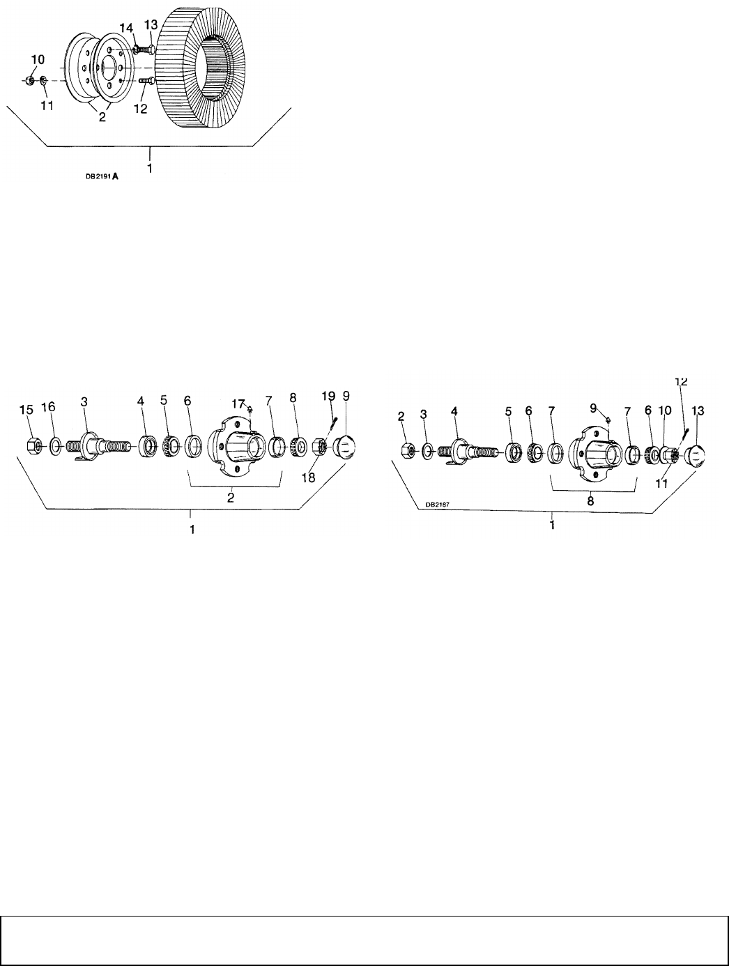
52 Parts
29977 (Rev. 1/23/2009)
TAILWHEEL & GAUGE WHEEL ASSEMBLY
GAUGE WHEEL & TAILWHEEL HUB & AXLE ASSEMBLY
The light-duty or standard hub with 1" axle shaft was used on the tailwheel on early machines and must be used with
#12876 yoke with offset side arm and 1" hole. It is also used on current production for cutter head gauge wheels.
The heavy-duty hub with 1-1/4" axle shaft is used on current production and must be used with #12095 yoke with
straight side arm and 1-1/4" hole only.
Standard 1" Shaft Heavy-Duty 1-1/4" Shaft
REF
TAILWHEEL
PART
GAUGE
PART QTY DESCRIPTION
1 4676 ----- 1 4.00 x 8 Rim & laminated tire
2 4679 4679 1 4.00 x 8 Rim half
3 ----- 25807 1 4.00 x 8 Rim & tire, 14" diameter
10 835 * 835 * 4 3/8 NC Hex nut, plated
11 838 * 838 * 4 3/8 Standard lock washer
12 839 * 839 * 4 3/8 NC x 1 HHCS GR5
13 4119 4119 4 1/2 NF x 1 HHCS GR5
14 855 * 855 * 4 1/2 Extra-heavy lock washer
* Standard hardware, obtain locally
REF PART QTY DESCRIPTION
1 2302 1 Standard wheel hub with axle
2 2307 1 Cast hub with cups
3 2301 1 Axle for standard hub
4 6273 1 Seal, 1.5 x 2.37 x .5
5 2303 1 Bearing cone
6 2305 1 Bearing cup
7 2306 1 Bearing cup
8 2304 1 Bearing cone
9 6248 1 Hub cap - standard
15 3626 1-14 UNS Hex nut
16 3689 * 1" Standard lock washer
17 1972 * 1/4 - 28 Tapered thread grease fitting
18 513 3/4 NF Castle hex nut
19 1256 * 3/16 x 1 Cotter pin
* Standard hardware, obtain locally
REF PART QTY DESCRIPTION
1 4984 1 Heavy-duty hub with 1-1/4 axle
2 3626 1 1-14 UNS Hex nut
3 3689 * 1 1" Standard lock washer
4 6271 1 Long axle assembly for heavy hub
53141Seal
6 310 1 Bearing cone, 1.25 ID
7 309 1 Bearing cup, 2.441 OD
8 530 1 Hub (includes bearing cups, item 7)
9 1972 * 1 1/4 - 28 Tapered thread grease fitting
10 1257 * 1 3/4 Standard flat washer
11 5849 1 3/4 NF Slotted hex nut
12 1256 * 1 3/16 x 1 Cotter pin
13 531 1 Hub cap
* Standard hardware, obtain locally
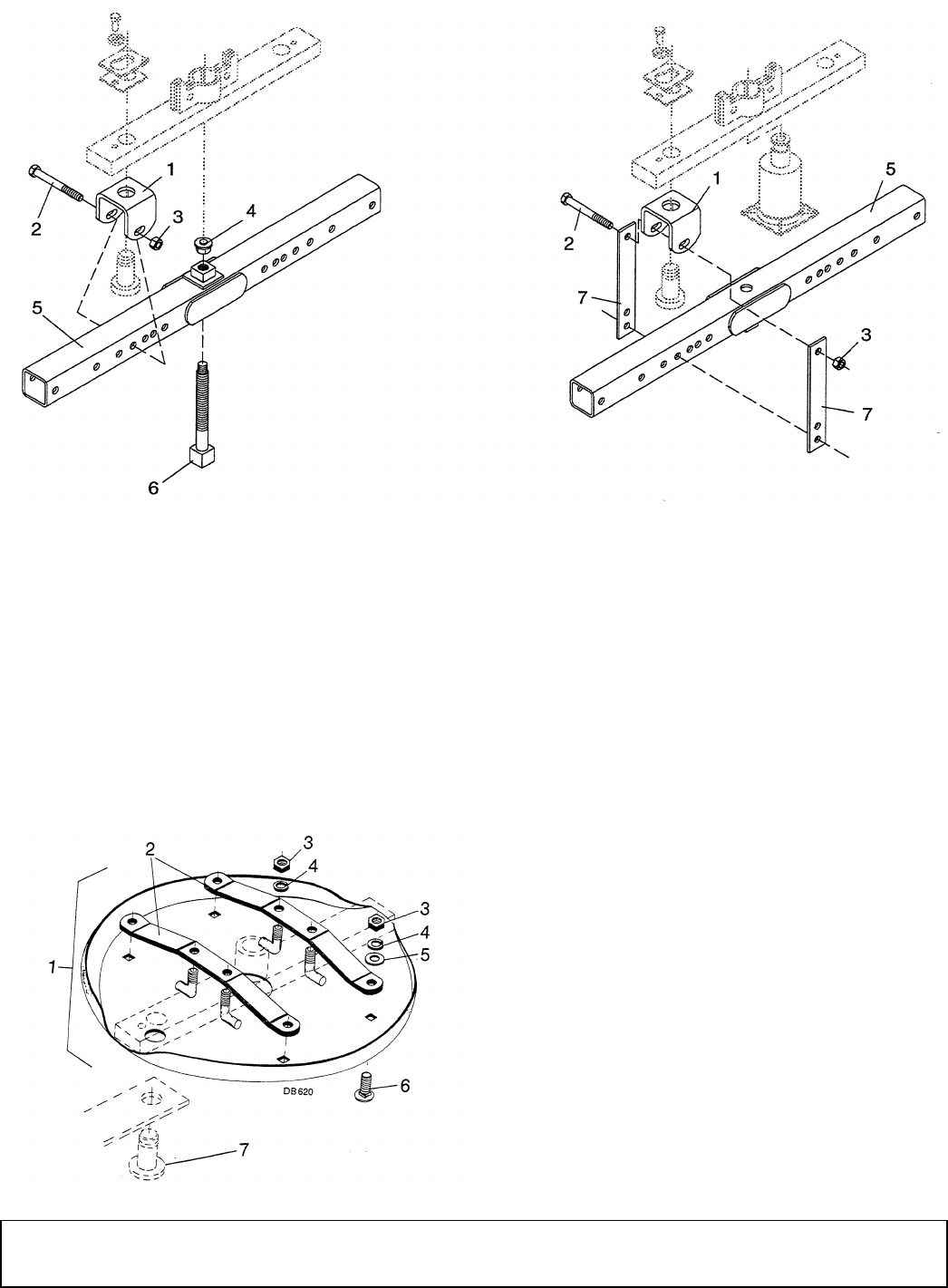
Parts 53
29977 (Rev. 1/23/2009)
CROSSBAR PULLER ASSEMBLY
STUMP JUMPER (OPTIONAL)
REF PART QTY DESCRIPTION
A 8811 1 Crossbar puller complete
1 19914 2 Crossbar puller clevis
2 3097 4 5/8 NC x 4-1/2 HHCS GR5
3 230 * 4 5/8 NC Hex nut
REF PART QTY DESCRIPTION
4 24879 1 Crossbar puller pad assembly
5 24876 1 Crossbar puller tube assembly
6 24881 1 Crossbar puller screw assembly
7 24885 4 Crossbar puller link
* Standard hardware, obtain locally
REF PART QTY DESCRIPTION
1 12785 1 Stump jumper complete
2 32641 2 Stump jumper strap
3 230 * 8 5/8 NC Hex nut
4 1286 * 8 5/8 Heavy lock washer
5 692 * 4 5/8 Standard flat washer
6 5607 * 4 5/8 NC x 1-1/2 Carriage bolt
7 32616 2 1-1/2 Blade pin - special, 2.54" (Not
included in stump jumper assembly)
- used on S106 only
* Standard hardware, obtain locally
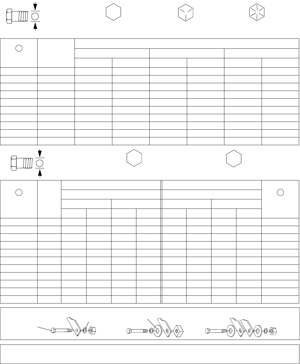
54 Appendix
Bolt Torque & Size Charts (Rev. 3/28/2007)
BOLT TORQUE CHART
Always tighten hardware to these values unless a different torque value or tightening procedure is listed for a specific
application.
Fasteners must always be replaced with the same grade as specified in the manual parts list.
Always use the proper tool for tightening hardware: SAE for SAE hardware and Metric for metric hardware.
Make sure fastener threads are clean and you start thread engagement properly.
All torque values are given to specifications used on hardware defined by SAE J1701 MAR 99 & J1701M JUL 96.
Diameter
(Inches)
Wrench
Size
MARKING ON HEAD
SAE 2 SAE 5 SAE 8
lbs-ft N-m lbs-ft N-m lbs-ft N-m
1/4" 7/16" 6 8 10 13 14 18
5/16"1/2"121719262737
3/8"9/16"233135474967
7/16"5/8"3648557578106
1/2" 3/4" 55 75 85 115 120 163
9/16" 13/16" 78 106 121 164 171 232
5/8" 15/16" 110 149 170 230 240 325
3/4" 1-1/8" 192 261 297 403 420 569
7/8" 1-5/16" 306 416 474 642 669 907
1" 1-1/2" 467 634 722 979 1020 1383
Diameter &
Thread Pitch
(Millimeters)
Wrench
Size
COARSE THREAD FINE THREAD
Diameter &
Thread Pitch
(Millimeters)
MARKING ON HEAD MARKING ON HEAD
Metric 8.8 Metric 10.9 Metric 8.8 Metric 10.9
N-m lbs-ft N-m lbs-ft N-m lbs-ft N-m lbs-ft
6 x 1.0 10 mm 8 6 11 8 8 6 11 8 6 x 1.0
8 x 1.25 13 mm 20 15 27 20 21 16 29 22 8 x 1.0
10 x 1.5 16 mm 39 29 54 40 41 30 57 42 10 x 1.25
12 x 1.75 18 mm 68 50 94 70 75 55 103 76 12 x 1.25
14 x 2.0 21 mm 109 80 151 111 118 87 163 120 14 x 1.5
16 x 2.0 24 mm 169 125 234 173 181 133 250 184 16 x 1.5
18 x 2.5 27 mm 234 172 323 239 263 194 363 268 18 x 1.5
20 x 2.5 30 mm 330 244 457 337 367 270 507 374 20 x 1.5
22 x 2.5 34 mm 451 332 623 460 495 365 684 505 22 x 1.5
24 x 3.0 36 mm 571 421 790 583 623 459 861 635 24 x 2.0
30 x 3.0 46 mm 1175 867 1626 1199 1258 928 1740 1283 30 x 2.0
A
SAE SERIES
TORQUE
CHART
SAE Bolt Head
Identification
SAE Grade 2
(No Dashes)
SAE Grade 5
(3 Radial Dashes)
SAE Grade 8
(6 Radial Dashes)
A
METRIC SERIES
TORQUE
CHART
Metric Bolt Head
Identification
8.8
Metric
Grade 10.9
10.9
Metric
Grade 8.8
A
A
A
Typical Washer
Installations
Lock Washer
Flat Washer
8/9/00
Bolt

Appendix 55
Bolt Torque & Size Charts (Rev. 3/28/2007)
BOLT SIZE CHART
NOTE: Chart shows bolt thread sizes and corresponding head (wrench) sizes for standard SAE and metric bolts.
ABBREVIATIONS
AG .............................................................. Agriculture
ASABE.................... American Society of Agricultural &
Biological Engineers (formerly ASAE)
ASAE ....... American Society of Agricultural Engineers
ATF ............................... Automatic Transmission Fluid
BSPP .............................British Standard Pipe Parallel
BSPTM ................British Standard Pipe Tapered Male
CV.....................................................Constant Velocity
CCW .............................................. Counter-Clockwise
CW............................................................... Clockwise
F ...................................................................... Female
FT .............................................................. Full Thread
GA .................................................................... Gauge
GR (5, etc.) ........................................... Grade (5, etc.)
HHCS ........................................Hex Head Cap Screw
HT........................................................... Heat-Treated
JIC .................Joint Industry Council 37° Degree Flare
LH .................................................................Left Hand
LT........................................................................... Left
m......................................................................... Meter
mm................................................................Millimeter
M.......................................................................... Male
MPa.........................................................Mega Pascal
N.......................................................................Newton
NC ......................................................National Coarse
NF ...........................................................National Fine
NPSM.....................National Pipe Straight Mechanical
NPT .......................................... National Pipe Tapered
NPT SWF .........National Pipe Tapered Swivel Female
ORBM .......................................... O-Ring Boss - Male
P...........................................................................Pitch
PBY ...................................................... Power-Beyond
psi..........................................Pounds per Square Inch
PTO ..................................................... Power Take Off
QD....................................................Quick Disconnect
RH ..............................................................Right Hand
ROPS ........................... Roll-Over Protective Structure
RPM ........................................Revolutions Per Minute
RT ....................................................................... Right
SAE ..........................Society of Automotive Engineers
UNC .....................................................Unified Coarse
UNF...........................................................Unified Fine
UNS......................................................Unified Special
5/16 3/81/2 5/83/4 7/8
SAE Bolt Thread Sizes
MM 25 50 75 100 125 150 175
IN 1 7
Metric Bolt Thread Sizes
8MM 18MM14MM12MM10MM 16MM
234 56

56 Index
29977 (Rev. 1/27/2006)
INDEX
ASSEMBLY
Dealer Set-up Instructions 29
DEALER CHECK LISTS
Delivery (Dealer’s Responsibility) 28
Pre-Delivery (Dealer’s Responsibility) 28
DEALER SERVICE
1-Spool, 3-Way Valve 27
Crossbar
Installation 23
Removal 22
Shimming 23
Gearbox Maintenance 21
Assembly - Cutter Head 22
Assembly - Input 22
Horizontal Housing Installation 22
Leakage Repair 21
Output Shaft Installation 22
Removal 22
Seal Installation 21
Spring-Loaded Wheel Yoke Adjustment 27
Universal Joint 25
Assembly 26
Disassembly 25
Repair 25
GENERAL
Abbreviations 55
Bolt Size Chart 55
Bolt Torque Chart 54
Introduction 2
Obtaining Replacement Manuals 2
Product Registration 2
Warranty
Product 57
Replacement Parts, Back Cover
OPERATION
Attach Cutter to Tractor 14
Cutting Height & Attitude Adjustment 14
General Mowing 15
Blade Selection 15
Brush and Ditch Bank Mowing 16
Cutter Head Lift 15
Tractor and Cutter Operation 15
General Tractor Operation 13
Pre-Operation Check List 14
Side Skid Adjustment 14
Storage 16
Tailwheel Adjustment 14
Tractor Stability 13
Transport 16
OWNER SERVICE
Blade Servicing 18
Installation 18
Removal 18
Sharpening 18
Chain Shielding Repair 19
Cleaning 19
Lubrication 17
Slip Clutch Adjustment 18
PARTS
Parts Index 35
SAFETY
Check Lists
Delivery (Dealer’s Responsibility) 28
Pre-Delivery (Dealer’s Responsibility) 28
Pre-Operation Check List 14
Free Mower Safety Video Order Form 5, 6
Safety & Instructional Decals 10
Safety Rules 7
Safety Symbols Explained 2
TROUBLE SHOOTING 20

F
-
3079 (Rev 11/24/2008)
Woods Equipment
Company
2606 South Illinois Route 2
Post Office Box 1000
Oregon, Illinois 61061 USA
800-319-6637 tel
800-399-6637 fax
www.WoodsEquipment.com
WARRANTY
(All Models Except Mow’n MachineTM Zero-Turn Mowers and Woods BoundaryTM Utility Vehicles)
Please Enter Information Below and Save for Future Reference.
Date Purchased: ____________________________ From (Dealer): __________________________________________
Model Number: ____________________________ Serial Number: __________________________________________
Woods Equipment Company (“WOODS”) warrants this product to be free from defect in material and workmanship. Except as otherwise set
forth below, the duration of this Warranty shall be for TWELVE (12) MONTHS COMMENCING ON THE DATE OF DELIVERY OF THE
PRODUCT TO THE ORIGINAL PURCHASER.
Woods backhoe models BH70-X, BH80-X, and BH90-X are warranted for two (2) years from the date of delivery to the original purchaser.
The warranty periods for specific parts or conditions are listed below:
Under no circumstances will this Warranty apply in the event that the product, in the good faith opinion of WOODS, has been subjected to
improper operation, improper maintenance, misuse, or an accident. This Warranty does not apply in the event that the product has been
materially modified or repaired by someone other than WOODS, a WOODS authorized dealer or distributor, and/or a WOODS authorized
service center. This Warranty does not cover normal wear or tear, or normal maintenance items. This Warranty also does not cover repairs made
with parts other than those obtainable through WOODS.
This Warranty is extended solely to the original purchaser of the product. Should the original purchaser sell or otherwise transfer this product to
a third party, this Warranty does not transfer to the third party purchaser in any way. There are no third party beneficiaries of this Warranty.
WOODS makes no warranty, express or implied, with respect to engines, batteries, tires or other parts or accessories not manufactured by
WOODS. Warranties for these items, if any, are provided separately by their respective manufacturers.
WOODS’ obligation under this Warranty is limited to, at WOODS’ option, the repair or replacement, free of charge, of the product if WOODS,
in its sole discretion, deems it to be defective or in noncompliance with this Warranty. The product must be returned to WOODS with proof
of purchase within thirty (30) days after such defect or noncompliance is discovered or should have been discovered, routed through the
dealer and distributor from whom the purchase was made, transportation charges prepaid. WOODS shall complete such repair or
replacement within a reasonable time after WOODS receives the product. THERE ARE NO OTHER REMEDIES UNDER THIS
WARRANTY. THE REMEDY OF REPAIR OR REPLACEMENT IS THE SOLE AND EXCLUSIVE REMEDY UNDER THIS
WARRANTY.
THERE ARE NO WARRANTIES WHICH EXTEND BEYOND THE DESCRIPTION ON THE FACE OF THIS WARRANTY. WOODS
MAKES NO OTHER WARRANTY, EXPRESS OR IMPLIED, AND WOODS SPECIFICALLY DISCLAIMS ANY IMPLIED WARRANTY
OF MERCHANTABILITY AND/OR ANY IMPLIED WARRANTY OF FITNESS FOR A PARTICULAR PURPOSE.
WOODS shall not be liable for any incidental or consequential losses, damages or expenses, arising directly or indirectly from the
product, whether such claim is based upon breach of contract, breach of warranty, negligence, strict liability in tort or any other legal
theory. Without limiting the generality of the foregoing, Woods specifically disclaims any damages relating to (i) lost profits, business,
revenues or goodwill; (ii) loss of crops; (iii) loss because of delay in harvesting; (iv) any expense or loss incurred for labor, supplies, substitute
machinery or rental; or (v) any other type of damage to property or economic loss.
This Warranty is subject to any existing conditions of supply which may directly affect WOODS’ ability to obtain materials or manufacture
replacement parts.
No agent, representative, dealer, distributor, serviceperson, salesperson, or employee of any company, including without limitation, WOODS,
its authorized dealers, distributors, and service centers, is authorized to alter, modify, or enlarge this Warranty.
Answers to any questions regarding warranty service and locations may be obtained by contacting:
Part or
Condition
Warranted
Model Number Duration (from date of delivery
to the original purchaser)
Gearbox
components
BW1260, BW1620, BW1800, BW2400 8 years
BW240HD 7 years
BB48X, BB60X, BB72X, BB84X, BB600X, BB720X, BB840X, BB6000X, BB7200X,
BB8400X, DS1260, DSO1260, DS1440, TS1680, BW126-3, BW180-3, BW240 6 years
PHD25, PHD35, PHD65, PHD95, 2162, 3240, DS96, DS120, RCC42, RM550-2,
RM660-2, RM990-3, PRD6000, PRD7200, PRD8400, 7144RD-2, 9180RD-2,
9204RD-2, S15CD, S20CD, S22CD, S25CD, S27CD
5 years
RDC54, RD60, RD72, TBW150C 3 years (1 year if used in rental or
commercial applications)
Blade
spindles
RM550-2, RM660-2, RM990-3, PRD6000, PRD7200, PRD8400, 7144RD-2, 9180RD-2,
9204RD-2 3 years
Rust-through BB600, BB720, BB840, BB6000, BB7200, BB8400, BW126-3, BW180-3, BW1260,
BW1800, BW240, BW240HD, 2162, 3240, DS1260, DSO1260, DS1440, TS1680 10 years

F-8494 (Rev. 6/23/2005)
Woods Equipment
Company
2606 South Illinois Route 2
Post Office Box 1000
Oregon, Illinois 61061
815-732-2141 tel
815-732-7580 fax
www.WoodsEquipment.com
©1995 Woods Equipment Company. All rights reserved. WOODS, the Woods logo, and "Tested. Proven. Unbeatable." are trademarks of Woods
Equipment Company. All other trademarks, trade names, or service marks not owned by Woods Equipment Company that appear in this manual are
the property of their respective companies or mark holders. Specifications subject to change without notice.
WARRANTY
(Replacement Parts For All Models Except Mow’n MachineTM
Zero-Turn Mowers and Woods BoundaryTM Utility Vehicles)
Woods Equipment Company (“WOODS”) warrants this product to be free from defect in material and
workmanship for a period of ninety (90) days from the date of delivery of the product to the original purchaser
with the exception of V-belts, which will be free of defect in material and workmanship for a period of 12 months.
Under no circumstances will this Warranty apply in the event that the product, in the good faith opinion of
WOODS, has been subjected to improper operation, improper maintenance, misuse, or an accident. This Warranty
does not cover normal wear or tear, or normal maintenance items.
This Warranty is extended solely to the original purchaser of the product. Should the original purchaser sell or
otherwise transfer this product to a third party, this Warranty does not transfer to the third party purchaser in any
way. There are no third party beneficiaries of this Warranty.
WOODS’ obligation under this Warranty is limited to, at WOODS’ option, the repair or replacement, free of
charge, of the product if WOODS, in its sole discretion, deems it to be defective or in noncompliance with this
Warranty. The product must be returned to WOODS with proof of purchase within thirty (30) days after
such defect or noncompliance is discovered or should have been discovered, routed through the dealer and
distributor from whom the purchase was made, transportation charges prepaid. WOODS shall complete
such repair or replacement within a reasonable time after WOODS receives the product. THERE ARE NO
OTHER REMEDIES UNDER THIS WARRANTY. THE REMEDY OF REPAIR OR REPLACEMENT IS THE
SOLE AND EXCLUSIVE REMEDY UNDER THIS WARRANTY.
THERE ARE NO WARRANTIES WHICH EXTEND BEYOND THE DESCRIPTION ON THE FACE OF THIS
WARRANTY. WOODS MAKES NO OTHER WARRANTY, EXPRESS OR IMPLIED, AND WOODS
SPECIFICALLY DISCLAIMS ANY IMPLIED WARRANTY OF MERCHANTABILITY AND/OR ANY
IMPLIED WARRANTY OF FITNESS FOR A PARTICULAR PURPOSE.
WOODS shall not be liable for any incidental or consequential losses, damages or expenses, arising directly
or indirectly from the product, whether such claim is based upon breach of contract, breach of warranty,
negligence, strict liability in tort or any other legal theory. Without limiting the generality of the foregoing,
Woods specifically disclaims any damages relating to (i) lost profits, business, revenues or goodwill; (ii) loss of
crops; (iii) loss because of delay in harvesting; (iv) any expense or loss incurred for labor, supplies, substitute
machinery or rental; or (v) any other type of damage to property or economic loss.
This Warranty is subject to any existing conditions of supply which may directly affect WOODS’ ability to obtain
materials or manufacture replacement parts.
No agent, representative, dealer, distributor, service person, salesperson, or employee of any company, including
without limitation, WOODS, its authorized dealers, distributors, and service centers, is authorized to alter, modify,
or enlarge this Warranty.
Answers to any questions regarding warranty service and locations may be obtained by contacting:
