Woodstock M1109 Users Manual
M1109 to the manual 41b1a01a-faa4-0274-a524-9556e2824a88
2015-02-03
: Woodstock Woodstock-M1109-Users-Manual-478112 woodstock-m1109-users-manual-478112 woodstock pdf
Open the PDF directly: View PDF ![]() .
.
Page Count: 74
MODEL M1109
COMBO LATHE/MILL
Phone: (360) 734-3482 • Online Technical Support: tech-support@shopfox.biz
COPYRIGHT © JULY 2006 BY WOODSTOCK INTERNATIONAL, INC.
WARNING: NO PORTION OF THIS MANUAL MAY BE REPRODUCED IN ANY SHAPE OR FORM WITHOUT
THE WRITTEN APPROVAL OF WOODSTOCK INTERNATIONAL, INC. Printed in China
#8232CR
OWNER'S MANUAL


SETUPELECTRICAL MAINTENANCE SERVICE PARTS
OPERATIONSSAFETYINTRODUCTION
USE THE QUICK GUIDE PAGE LABELS TO SEARCH OUT INFORMATION FAST!
Contents
INTRODUCTION ..................................................................................................3
Woodstock Technical Support ............................................................................ 3
Specifications ............................................................................................... 3
Controls and Features ..................................................................................... 4
SAFETY ............................................................................................................5
Standard Safety Instructions ............................................................................. 5
Additional Safety Instructions for Lathe/Mills ......................................................... 7
Avoiding Potential Injuries ............................................................................... 8
ELECTRICAL ......................................................................................................9
220V Operation ............................................................................................. 9
Extension Cords ............................................................................................ 9
Grounding ................................................................................................... 9
SETUP ........................................................................................................... 10
Inventory ...................................................................................................10
Cleaning Machine .........................................................................................11
Machine Placement .......................................................................................11
Uncrating and Lifting .....................................................................................12
Test Run and Break-In ....................................................................................13
LATHE OPERATIONS .......................................................................................... 14
General .....................................................................................................14
Power Supply ..............................................................................................14
Chuck and Faceplate Mounting .........................................................................15
Replacing Jaws ............................................................................................16
Using the Four-Jaw Chuck ..............................................................................17
Using the Faceplate ......................................................................................18
Using the Tailstock .......................................................................................19
Drilling with the Tailstock ...............................................................................19
Tailstock Alignment .......................................................................................20
Using Centers ..............................................................................................22
Using the Steady Rest ....................................................................................23
Using the Follow Rest ....................................................................................23
Setting Compound Slide ..................................................................................24
Using the Tool Post .......................................................................................24
Using Manual Feed ........................................................................................25
Setting RPM ................................................................................................26
Setting Power Feed Rate ................................................................................27
Threading Setup ...........................................................................................28
Change Gear Chart ........................................................................................29
Continued on next page

USE THE QUICK GUIDE PAGE LABELS TO SEARCH OUT INFORMATION FAST!
SETUP ELECTRICAL
MAINTENANCE
SERVICE
PARTS OPERATIONS SAFETY INTRODUCTION
MILLING OPERATIONS ........................................................................................ 30
Installing Tools ............................................................................................30
Removing Tools ............................................................................................30
Headstock Positioning ....................................................................................31
Quill Travel ................................................................................................31
Table Travel ...............................................................................................32
Start Up and Spindle Break-in Procedures ............................................................32
Setting RPM ................................................................................................33
MAINTENANCE ................................................................................................. 34
General Maintenance .....................................................................................34
General Cleaning ..........................................................................................34
General Lubrication ......................................................................................34
Adjusting/Replacing .....................................................................................35
the V-Belt ..................................................................................................35
SERVICE ......................................................................................................... 36
Cross Slide Backlash ......................................................................................36
Cross Slide, Half-Nut, and Compound Slide Gib Adjustments .....................................36
Electrical Component and Connection Index .........................................................37
Electrical Connections ..................................................................................38
Wiring Diagram ............................................................................................40
Troubleshooting ...........................................................................................41
PARTS ........................................................................................................... 43
Lathe Change Gear Housing Diagram ..................................................................44
(0000 Series Parts) ........................................................................................44
Thread Dial Diagram ......................................................................................46
(1000 Series Parts) ........................................................................................46
Leadscrew Gearbox Diagram ............................................................................48
(2000 Series Parts) ........................................................................................48
Compound Rest and Tool Post Diagram ...............................................................50
(2500 Series Parts) ........................................................................................50
Bed Diagram ...............................................................................................52
(3000 Series Parts) ........................................................................................52
Steady Rest and Follow Rest Diagram .................................................................54
(3500 Series Parts) ........................................................................................54
Apron Diagram .............................................................................................56
(4000 Series Parts) ........................................................................................56
Tailstock Diagram .........................................................................................58
(5000 Series Parts) ........................................................................................58
Mill Column Diagram ......................................................................................60
(6000 Series Parts) ........................................................................................60
Headstock Diagram .......................................................................................62
(7000 Series Parts) ........................................................................................62
Accessories and Labels Diagram ........................................................................64
(8000 Series Parts) ........................................................................................64
Main Wiring Box Diagram ................................................................................66
(9000 Series Parts) ........................................................................................66
Warranty ....................................................................................................68
Warranty Registration ....................................................................................69

-3-
M1109 Combo Lathe/Mill
INTRODUCTION
Woodstock Technical Support
INTRODUCTION
Your new SHOP FOX® Model M1109 Combo Lathe/Mill has been specially designed to provide many years
of trouble-free service. Close attention to detail, ruggedly built parts and a rigid quality control program
assure safe and reliable operation.
Woodstock International, Inc. is committed to customer satisfaction. Our intent with this manual is to
include the basic information for safety, setup, operation, maintenance, and service of this product.
We stand behind our machines! In the event that questions arise about your machine, please contact
Woodstock International Technical Support at (360) 734-3482 or send e-mail to: tech-support@shopfox.
biz. Our knowledgeable staff will help you troubleshoot problems and process warranty claims.
If you need the latest edition of this manual, you can download it from http://www.shopfox.biz.
If you have comments about this manual, please contact us at:
Woodstock International, Inc.
Attn: Technical Documentation Manager
P.O. Box 2309
Bellingham, WA 98227
Milling Motor ........................................ 3⁄4" HP, 220V, 7 Amps, Single-Phase, TEFC
Lathe Motor ..................................... 11⁄2" HP, 220V, 10 Amps, Single-Phase, TEFC
Lathe Swing Over Bed ........................................................................ 121⁄2"
Mill/Drill Swing .................................................................................141⁄2"
Mill/Drill Spindle to Worktable Capacity ...................................................171⁄4"
Distance Between Centers ...................................................................291⁄2"
Spindle Bore ..................................................................................... 11⁄2"
Lathe Spindle Taper .......................................................................... MT #5
Mill/Drill Spindle Taper ............................................................R8, 7⁄16"-20 TPI
Tailstock Taper ................................................................................ MT #3
Tailstock Barrel Travel ........................................................................315⁄16"
Cross Slide Travel ............................................................................... 61⁄4"
Number of Mill/Drill Speeds ...................................................................... 4
Mill/Drill Speed Range ................................................240, 600, 1100, 2700 RPM
Tilting Headstock .........................................................................90° L & R
Number of Lathe Speeds ......................................................................... 12
Lathe Speeds ...........75, 110, 140, 200, 240, 350, 420, 600, 720, 1050, 1250, 1900 RPM
Thread Range (inches) ........................................................... 27 @ 8 - 120 TPI
Thread Range (metric) ........................................................ 18 @ 0.2 - 3.0 mm
4-Jaw Chuck ........................................................................................ 8"
3-Jaw Chuck ................................................................ w/Int. & Ext. Jaws, 6"
Drill Chuck ............................................................................ 1-13mm JT-33
Faceplate ........................................................................................... 8"
Tool Holder ................................................................ 4-Way Turret Tool Post
Change Gears ....................................................................................Steel
Dead Centers ............................................................................ MT5 & MT3
Approximate Net Weight .................................................................1200 lbs.
Specifications
-4-
M1109 Combo Lathe/Mill
INTRODUCTION
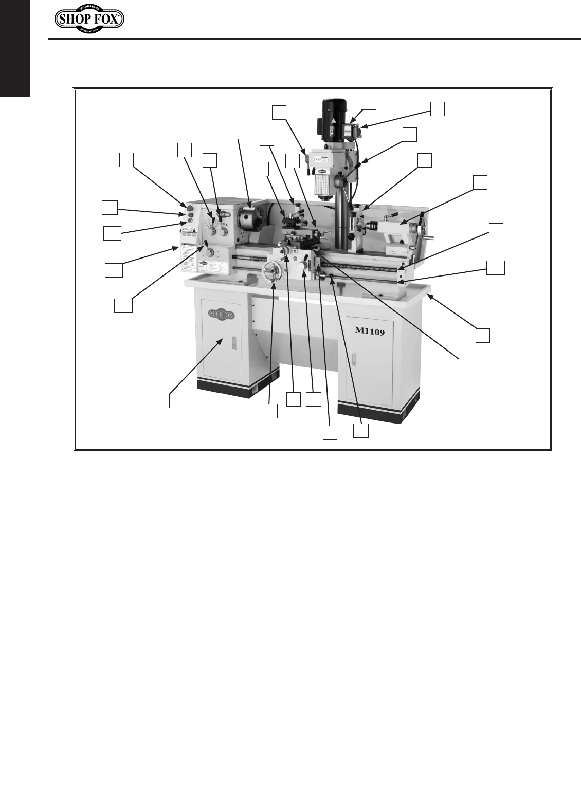
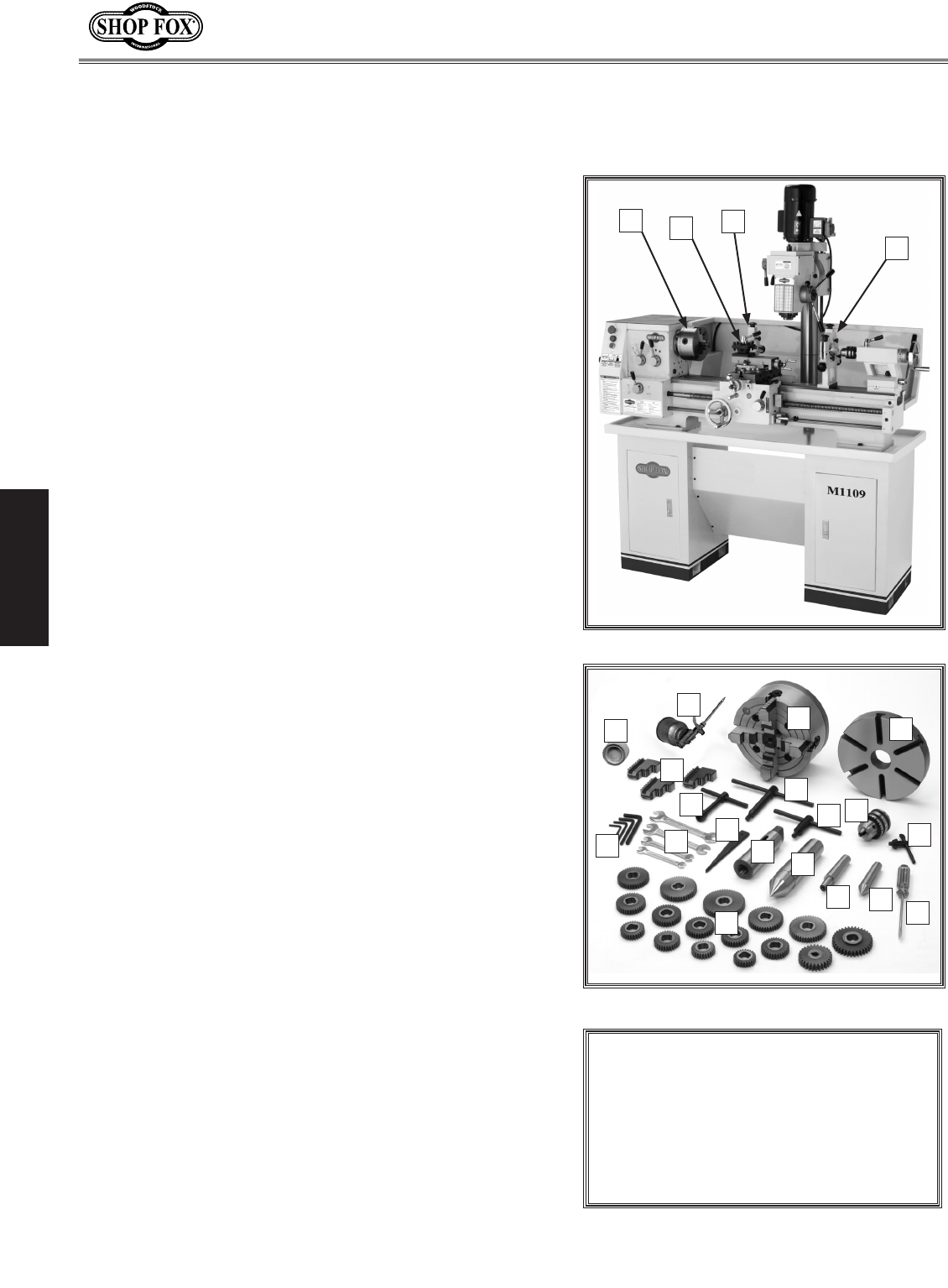
M1109 Combo Lathe/Mill.
Controls and Features
O. Feed Rod
P. Chip Tray and Drip Pan
Q. Longitudinal and Cross Feed Lever
R. Spindle ON/OFF Rotation Lever
S. Thread Dial
T. Half Nut Lever
U. Cross Slide Handle
V. Manual Feed Hand Wheel
W. Storage Cabinet
X. Lead Screw Direction Lever
Y. Side Cover
Z. Jog Button
AA. Power Lamp
A. Lathe Emergency Stop Button
B. Spindle Speed Lever
C. Spindle Range Lever
D. 3-Jaw Chuck
E. Four-Way Tool Post
F. Follow Rest
G. Milling Speed Levers
H. Compound Rest
I. Elevation Handwheel
J. Mill Power/Emergency Stop Button
K. Milling Rack Handles
L. Follow Rest
M. Tailstock
N. Lead Screw
AA
F
G
L
D
J
E
K
B
M
N
T
P
ACH
Y
V
O
X
Z
U
R
S
I
Q
W

-5-
M1109 Combo Lathe/Mill
SAFETY
SAFETY
READ MANUAL BEFORE OPERATING MACHINE.
FAILURE TO FOLLOW INSTRUCTIONS BELOW WILL
RESULT IN PERSONAL INJURY.
Standard Safety Instructions
1. Thoroughly read the Instruction Manual before operating your machine. Learn the applications,
limitations and potential hazards of this machine. Keep the manual in a safe and convenient place
for future reference.
2. Keep work area clean and well lighted. Clutter and inadequate lighting invite potential hazards.
3. Ground all tools. If a machine is equipped with a three-prong plug, it must be plugged into a three-
hole grounded electrical receptacle or grounded extension cord. If using an adapter to aid in accom-
modating a two-hole receptacle, ground using a screw to a known ground.
4. Wear eye protection at all times. Use safety glasses with side shields or safety goggles that meet
the appropriate standards of the American National Standards Institute (ANSI).
5. Avoid dangerous environments. Do not operate this machine in wet or open flame environments.
Airborne dust particles could cause an explosion and severe fire hazard.
6. Ensure all guards are securely in place and in working condition.
7. Make sure switch is in the OFF position before connecting power to machine.
8. Keep work area clean, free of clutter, grease, etc.
9. Keep children and visitors away. Visitors must be kept at a safe distance while operating unit.
10. Childproof your workshop with padlocks, master switches or by removing starter keys.
11. Stop and disconnect the machine when cleaning, adjusting or servicing.
Indicates an imminently hazardous situation which, if not avoided, WILL
result in death or serious injury.
Indicates a potentially hazardous situation which, if not avoided, COULD
result in death or serious injury.
Indicates a potentially hazardous situation which, if not avoided, MAY
result in minor or moderate injury.
This symbol is used to alert the user to useful information about proper
operation of the equipment, and/or a situation that may cause damage
to the machinery.
NOTICE

-6-
M1109 Combo Lathe/Mill
SAFETY
12. Do not force tool. The machine will do a safer and better job at the rate for which it was
designed.
13. Use correct tool. Do not force machine or attachment to do a job for which it was not designed.
14. Wear proper apparel. Do not wear loose clothing, neck ties, gloves, jewelry, and secure long hair
away from moving parts.
15. Remove chuck keys, rags, and tools. Before turning the machine on, make it a habit to check that
all chuck keys and wrenches have been removed.
16. Avoid using an extension cord. But if you must use one, examine the extension cord to ensure it is
in good condition. Immediately replace a damaged extension cord. Always use an extension cord that
uses a ground pin and connected ground wire. Use an extension cord that meets the amp rating on
the motor nameplate. If the motor is dual voltage, be sure to use the amp rating for the voltage you
will be using. If you use an extension cord with an undersized gauge or one that is too long, excessive
heat will be generated within the circuit, increasing the chance of a fire or damage to the circuit.
17. Keep proper footing and balance at all times.
18. Lock the mobile base from moving before feeding the workpiece into the machine.
19. Do not leave machine unattended. Wait until it comes to a complete stop before leaving the
area.
20. Perform machine maintenance and care. Follow lubrication and accessory attachment instructions
in the manual.
21. If at any time you are experiencing difficulties performing the intended operation, stop using the
machine! Then contact our technical support or ask a qualified expert how the operation should be
performed.
22. Be aware that certain materials may cause an allergic reaction in people and animals, especially
when exposed to fine dust. Make sure you know what type of material dust you will be exposed to
and the possibility of an allergic reaction.
23. Habits—good and bad—are hard to break. Develop good habits in your shop and safety will become
second-nature to you.
-7-
M1109 Combo Lathe/Mill
SAFETY
Additional Safety Instructions for
Lathe/Mills
USE this and other machinery with caution
and respect. Always consider safety first,
as it applies to your individual working
conditions. No list of safety guidelines can
be complete—every shop environment is
different. Failure to follow guidelines could
result in serious personal injury, damage
to equipment or poor work results.
READ and understand this
entire instruction manual
before using this machine.
Serious personal injury
may occur if safety and
operational information is
not understood and fol-
lowed. DO NOT risk your
safety by not reading!
1. UNDERSTANDING THE MACHINE: Read and understand this manual before operating machine.
2. CLEANING MACHINE: Do not clear chips by hand. Use a brush, and never clear chips while the
lathe is turning.
3. USING CORRECT TOOLING: Always select the right cutter for the job, and make sure cutters are
sharp. The right tool decreases strain on the lathe components and avoids unsafe cutting.
4. ELIMINATING A PROJECTILE HAZARD: Always remove the chuck key, and never walk away from
the lathe leaving the chuck key installed.
5. SECURING A WORKPIECE: Make sure workpiece is properly held in chuck before starting lathe. A
workpiece thrown from the chuck will cause severe injury.
6. CHUCK SAFETY: Chucks are surprisingly heavy and awkward to hold, so protect your hands and the
lathe ways. Always use a chuck cradle or piece of plywood over the lathe ways.
7. WORKPIECE SUPPORT: Support a long workpiece if it extends from the headstock so it will not
wobble violently when the lathe is turned on. If workpiece extends more than 2.5 times its diam-
eter from the chuck, support it by a center or steady rest or it may deflect and fall out of the
chuck during cutting.
8. AVOIDING STARTUP INJURIES: Make sure workpiece, cutting tool, and tool post have adequate
clearance before starting lathe. Check chuck clearance and saddle clearance before starting the
lathe. Make sure spindle RPM is set correctly for part diameter before starting the lathe. Large
parts can be ejected from the chuck if the chuck speed is set too high.
9. AVOIDING OVERLOADS: Always use the appropriate feed and speed rates.
10. AVOIDING ENTANGLEMENT INJURIES: Never attempt to slow or stop the lathe chuck or mill spin-
dle by hand; and tie back long hair, ponytails, loose clothing, and sleeves so they do not dangle.
11. MAINTAINING A SAFE WORKPLACE: Never leave lathe unattended while it is running.
12. PREVENTING AN APRON-CHUCK CRASH: Always release automatic feeds after completing a job.
-8-
M1109 Combo Lathe/Mill
SAFETY
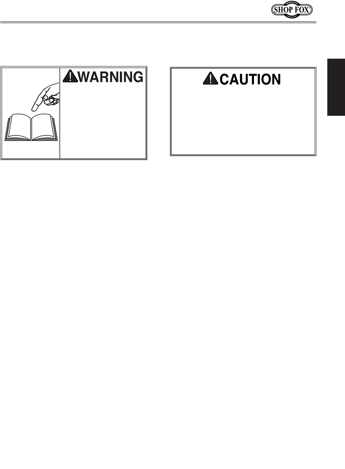
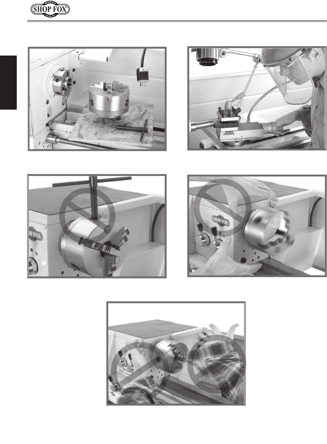
Avoiding Potential Injuries
Figure 3. Always wear face and eye protection
when using this lathe/mill.
Figure 2. Never walk away from the lathe/mill
leaving the chuck key inserted in the chuck.
Figure 1. Always protect the bed ways, and
unplug the lathe/mill when retooling.
Figure 4. Never use hands to stop or slow the
chuck when shutting down the lathe/mill.
Figure 5. Never wear loose clothing or gloves
when working with the lathe/mill.
-9-
M1109 Combo Lathe/Mill
ELECTRICAL
TURN OFF and LOCK your
master power switch so
no power is available
to the lathe/mill before
connecting electrical
wires! If you ignore
this warning serious
electrical shock may
occur, causing injury or
death!
OFF
DO NOT attempt to work on your
electrical system if you are unsure
about electrical codes and wiring!
Seek assistance from a qualified elec-
trician. Ignoring this warning can cause
electrocution!
ELECTRICAL
We do not recommend using an extension cord for 220V
operation. When it is necessary to use an extension cord,
use the following guidelines:
• Use cords rated for Standard Service
• Never exceed a length of 50 feet
• Ensure cord has a ground wire and pin
• Do not use cords in need of repair
Extension Cords
Grounding
This machine must be grounded! Verify that any exist-
ing electrical outlet and circuit you intend to plug into
is actually grounded. If it is not, it will be necessary to
run a separate copper grounding wire, of the appropri-
ate size, from the outlet to a known ground. Under no
circumstances should you connect your machine to an
ungrounded power source or electrocution or severe
shock could occur.
220V Operation
The SHOP FOX® MODEL M1109 Combo Lathe/Mill oper-
ates at 220 volt single-phase only. Only connect this
machine to a dedicated circuit (wire, breaker, plug,
receptacle) with a verified ground, using the recommend-
ed circuit size and NEMA 6-20 plug/receptacle (Figure 6)
listed at the bottom of this page.
Never replace a circuit breaker with one of higher amper-
age without consulting a qualified electrician to ensure
compliance with wiring codes. If you are unsure about
the wiring codes in your area or plan to connect your
machine to a shared circuit, you may create a fire haz-
ard—consult a qualified electrician to reduce this risk.
Operating Voltage Full Load Amp Draw Min. Circuit Size Plug/Receptacle Extension Cord
220V Single-Phase 17 Amps 20A NEMA 6-20 12 Gauge
Figure 6. NEMA 6-20 plug and recepticle.
6-20P 6-20R
-10-
M1109 Combo Lathe/Mill
SETUP
NOTICE
If any parts are missing, find the part
number in the back of this manual
and contact Woodstock International,
Inc. at (360) 734-3482 or at tech-
support@shopfox.biz.
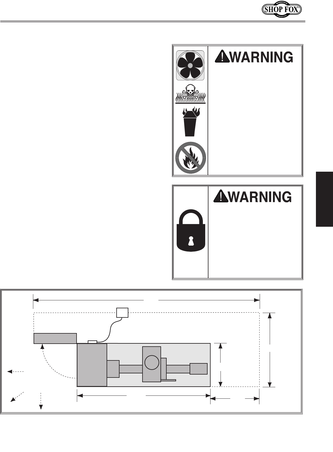
The following is an inventory of the accessories shipped
with your SHOP FOX® Model M1109 Lathe/Mill.
Installed Accessories (Figure 7) Qty.
A. 6" Three-Jaw Chuck .......................................1
B. 4-Way Tool Post and Compound Rest ..................1
C. Follow Rest .................................................1
D. Compound Rest ............................................1
Packaged Accessories (Figure 8)
E. 8" Four-Jaw Universal Chuck ............................1
F. 8" Faceplate ................................................1
G. Four-Jaw Chuck Key ......................................1
H. Drill Chuck (1-13mm, JT-33) ............................1
I. Wrench Set (8/10, 10/12, 14/17, 17/19 mm) ....1 EA
J. Hex Wrench Set (2, 4, 6, 8 mm) ....................1 EA
K. Three-Jaw Chuck Key .....................................1
L. Oil Can ......................................................1
M. Dead Center MT#5 .........................................1
N. #2 Standard Screwdriver .................................1
O. Wedge .......................................................1
P. Tool Post T-Handle Wrench ..............................1
Q. Dead Center MT#3 .........................................1
R. Three-Jaw Chuck Internal Jaws .........................3
S. Taper Adapter MT#3 to MT#5 ...........................1
T. Arbor JT-33 to MT#3 ......................................1
U. Spot Paint ...................................................1
V. Drill Chuck Key .............................................1
W. Change Gear Set ...........................................1
— Keyed Drive Gear (24-fine Tooth), (Installed) .....1
— Keyed Drive Gear Set (28 & 35-Coarse Tooth) .....1
— Change Gear (24-tooth, One Installed) .............2
— Change Gear (25-tooth, One Installed) .............2
— Change Gear (27-tooth) ...............................1
— Change Gear (28-tooth) ...............................1
— Change Gear (30-tooth) ...............................1
— Change Gear (32-tooth) ...............................2
— Change Gear (34-tooth) ...............................1
— Change Gear (35-tooth) ...............................1
— Change Gear (36-tooth) ...............................1
— Change Gear (40-tooth) ...............................1
— Change Gear (42-tooth) ...............................1
— Change Gear (44-tooth) ...............................1
— Change Gear (46-tooth) ...............................1
— Change Gear (48-tooth, Installed) ...................1
— Change Gear (50-tooth, Installed) ...................1
— Change Gear (52-tooth) ...............................1
— Change Gear (60-tooth, Installed) ...................1
Inventory
Figure 7. Installed accessories.
Figure 8. Packaged accessories.
G
E
H
F
D
A
SETUP
K
JV
W
T
U
R
Q
P
O
N
M
L
IS
BC
-11-
M1109 Combo Lathe/Mill
SETUP
• Floor Load: Your lathe/mill is a heavy load (1200
lbs.) distributed in a 61
3/4" x 27
1/2" footprint. Place
this machine on concrete floors only. The floor
MUST be level, or the lathe/mill frame and ways
may distort over time.
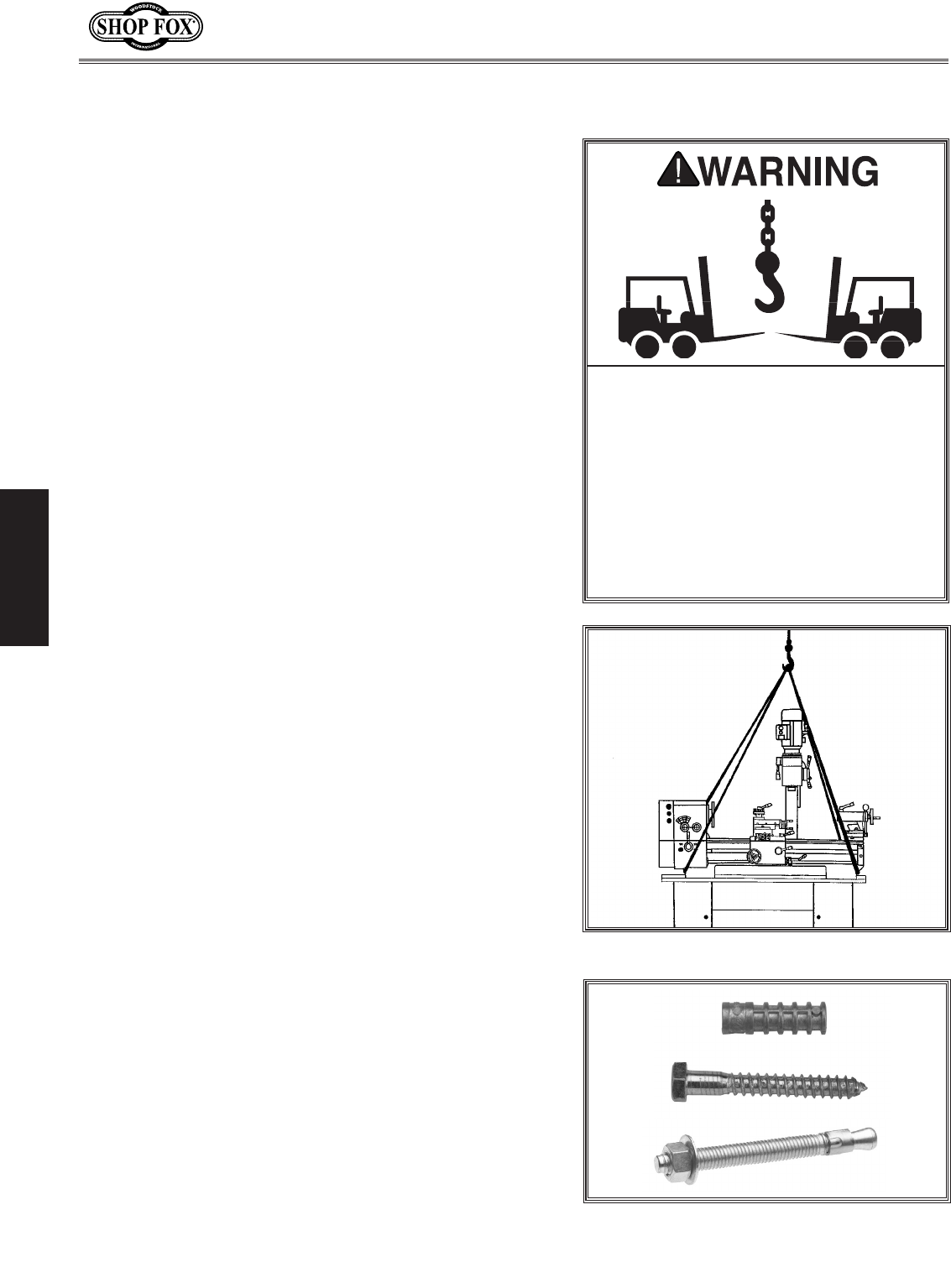
• Working Clearances: Consider existing and
anticipated needs, service panel access, length of
rods to be loaded into the lathe/mill, and space for
auxiliary stands, work tables or other machinery
when establishing a location for your lathe/mill
(see Figure 9 for minimum wall clearances).
• Lighting: Lighting should be bright enough to
eliminate shadow and prevent eye strain.
• Electrical: Outlets must be located near each
machine, so power cords are clear of high-traffic
areas. Follow local electrical codes for proper
installation.
Cleaning Machine
The ways and other unpainted parts of your lathe/mill
are coated with a waxy grease that protects them from
corrosion during shipment. Clean this grease off with a
solvent cleaner or citrus-based degreaser. DO NOT use
chlorine-based solvents such as brake parts cleaner, lac-
quer thinner, or acetone—if you happen to splash some
onto a painted surface, you will ruin the finish.
Machine Placement
ALWAYS work in well-
ventilated areas far from
possible ignition sources
when using solvents to clean
machinery. Many solvents
are toxic when inhaled or
ingested. Use care when
disposing of waste rags
and towels to be sure
they DO NOT create fire
or environmental hazards.
NEVER use gasoline or
petroleum-based solvents
to clean your lathe/mill.
Figure 9. Minimum wall clearances.
MAKE your shop “child safe.”
Ensure that your workplace
is inaccessible to youngsters
by closing and locking all
entrances when you are
away. NEVER allow untrained
visitors in your shop when
assembling, adjusting or
operating equipment.
-12-
M1109 Combo Lathe/Mill
SETUP
This lathe/mill has been carefully crated. If you notice it
has been damaged, contact your authorized SHOP FOX®
dealer immediately.
To unpack and move the lathe/mill, do these steps:
1. Read Pages 9 & 11 to prepare the lathe/mill loca-
tion, and install or prepare holes for any floor
mounting fasteners (Figure 11).
2. Gather the following items:
• Fork Lift or 2-ton hoist, and driver or operator.
• 1 Ton lifting straps and hooks.
3. Unbolt the crate sides and remove the top and
sides.
4. Insert two lifting straps under the bedways and
behind the feed rod and the lead screw as shown in
Figure 10 , and support the lathe with the lifting
straps and lifting device.
5. Move the apron so it located between the headstock
and the mill column as shown in Figure 10 to bal-
ance the load.
6. Unbolt the lathe/mill from the pallet.
7. Slowly raise the lathe/mill off of the pallet and
carefully move the lathe/mill to your prepared loca-
tion.
8. With the lathe/mill securely resting on the floor,
shim between the floor and cabinet base as required
to make the ways level at all four corner locations
as indicated with a machinist's level.
9. Secure the lathe/mill to the floor, but DO NOT over-
tighten the fasteners.
10. Recheck the ways to make sure the ways are still
level, re-shim as required.
Uncrating and Lifting
The MODEL M1109 weighs approximate-
ly 1200 lbs. You will need power lifting
equipment and assistance to remove
this machine from the pallet and posi-
tion it. Inspect all lifting equipment and
make sure that all is in perfect working
order and is rated for the load before
attempting to lift and move this lathe/
mill. Ignoring this warning may lead to
serious personal injury or death.
Figure 10. Lifting strap locations.
Figure 11. Floor fasteners.
-13-
M1109 Combo Lathe/Mill
SETUP
Test Run and Break-In
The purpose of the test run is to make sure the lathe/
mill and safety features operate correctly before pro-
ceeding with additional setup.
To begin the test run procedure, do these steps:
1. Make sure the lathe/mill is lubricated and headstock
oil level is full. Refer to Page 34 if required.
2. Make sure the chuck is bolted to the spindle.
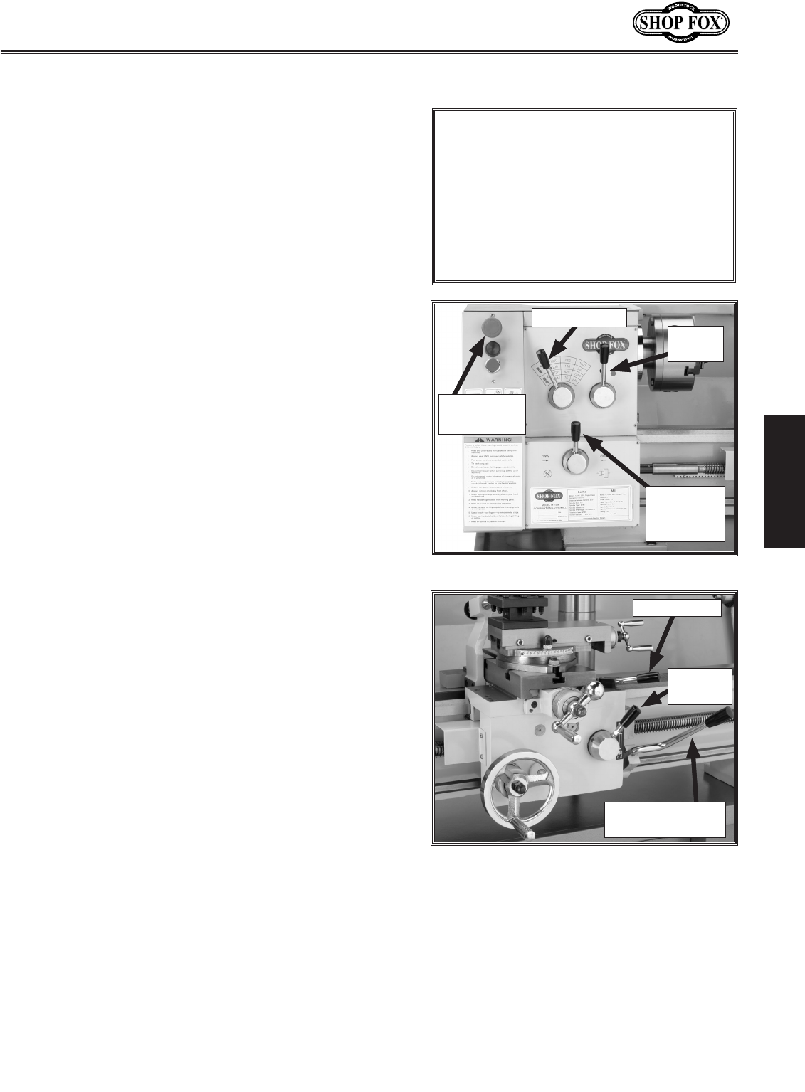
3. Move the spindle speed lever to the 75 RPM posi-
tion, the range lever to the red-dot position, and
the lead screw lever to the neutral position as
shown in Figure 12.
4. Rotate the red emergency stop button (Figure 12)
clockwise so it pops to the outward position.
5. Move the half-nut lever upward to disengage the
apron, and move the feed lever to the neutral or
central position (see Figure 13).
6. Move the spindle rotation ON/OFF lever to its cen-
tral position (OFF) as shown in Figure 13, and con-
nect the lathe to power so the green lamp is lit.
7. Move the Spindle Rotation ON/OFF lever up or down
so the chuck turns, then push the emergency stop
button to make sure the lathe stops.
8. Move the Spindle Rotation ON/OFF lever to neutral,
reset the red emergency stop button, and use the
spindle lever to start the lathe again.
• If you hear squealing or grinding noises, turn the
machine OFF immediately and correct any prob-
lem before further operation.
• If the problem is not readily apparent, refer to
Troubleshooting on Page 42.
9. Let the lathe/mill run for a minimum of 10 minutes.
10. Turn the lathe/mill OFF, move levers to the next
highest RPM and repeat this step for each RPM set-
ting in Low and High range. NEVER SHIFT LATHE/MILL
GEARS WHEN MACHINE IS OPERATING.
11. Change the lubricant in the headstock with Mobil
DTE® Oil or with an equivalent.
Range
Lever
Speed Lever
Emergency
Stop Button
Leadscrew
Direction
Lever
Figure 12. Headstock control levers.
Figure 13. Apron control levers.
Spindle Rotation
ON/OFF lever.
Feed Lever
Half-Nut
Lever
Make sure all power feed levers and
dials are disengaged before starting
the lathe/mill! Thoroughly familiarize
yourself with all the controls and
their functions before using any power
feed! NEVER SHIFT LATHE/MILL GEARS
WHEN MACHINE IS OPERATING.
NOTICE
-14-
M1109 Combo Lathe/Mill
OPERATIONS
LATHE OPERATIONS
General
TURN OFF and LOCK your master power
switch so no power is available to the
lathe/mill, and make sure the spindle
is stopped before proceeding with any
adjustments or maintenance. Failure to
comply may result in serious personal
injury or death.
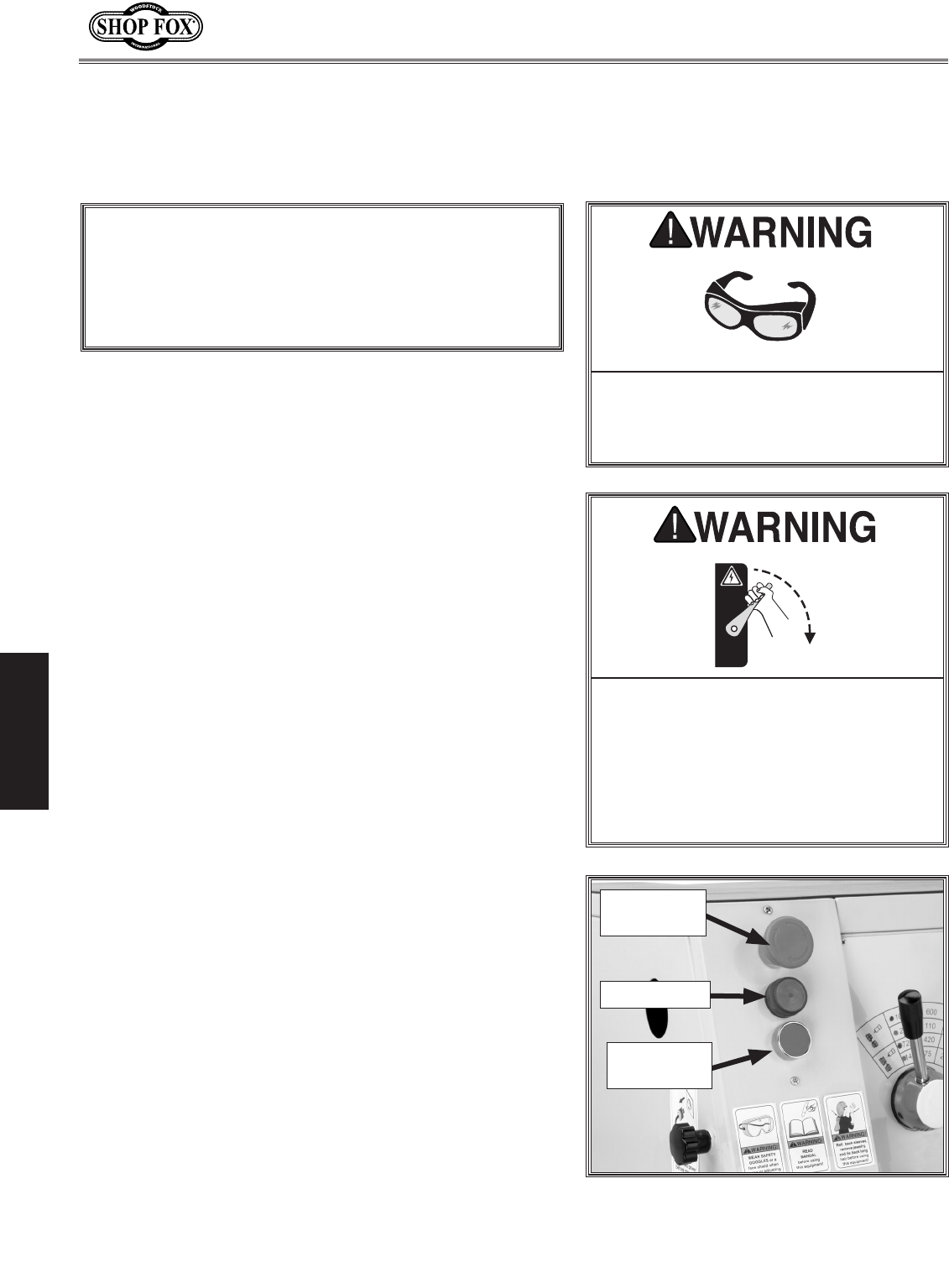
Always wear safety glasses when oper-
ating this lathe/mill. Failure to comply
may result in serious eye injury caus-
ing blindness.
Power Supply
When illuminated, the power lamp (Figure 14) indicates
that the power is being supplied to the lathe/mill. If you
press the red emergency stop button, you will cut power
for machine operations. Twisting the emergency stop but-
ton clockwise and letting it pop out will restore power
for machine operations and reset the switch.
Note: The Spindle Rotation ON/OFF Lever (Figure 13)
on the apron starts the spindle motor in a particular
direction.
Figure 14. Power lamp and emergency
stop location.
Emergency
Stop Button
The Model M1109 will perform many types of operations
that are beyond the scope of this manual. Many of these
operations can be dangerous or deadly if performed
incorrectly.
The instructions in this section are written with the
understanding that the operator has the necessary
knowledge and skills to operate this machine. If at any
time you are experiencing difficulties performing any
operation, stop using the machine!
If you are an inexperienced operator, we strongly rec-
ommend that you read books, trade articles, or seek
training from an experienced lathe/mill operator before
performing any unfamiliar operations. Above all, your
safety should come first!
Complete the Test Run and Break-In procedure on
Page 13 before using this lathe/mill for any cutting or
threading operations; otherwise, gear box damage will
occur.
NOTICE
Power Lamp
OFF
Spindle Jog
Button
-15-
M1109 Combo Lathe/Mill
OPERATIONS
Chuck and Faceplate
Mounting
The three-jaw scroll chuck has hardened steel jaws that
self-center the workpiece within 0.002"-0.003". An extra
set of jaws is included for machining larger workpieces.
The four-jaw chuck also has hardened steel jaws but are
adjusted independently to hold an off-center workpiece.
Each jaw can be removed from the chuck body and
reversed for special clamping applications.
The cast-iron faceplate has slots for T-bolts that hold
clamping fixtures. This face plate and aftermarket clamp-
ing hardware will hold non-cylindrical parts such as cast-
ings for many types of turning operations.
Both chucks and the faceplate are removed and installed
the same way.
To remove and install the chuck or face plate, do these
steps:
1. DISCONNECT POWER TO THE LATHE/MILL!
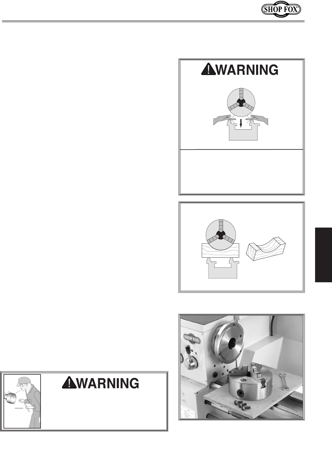
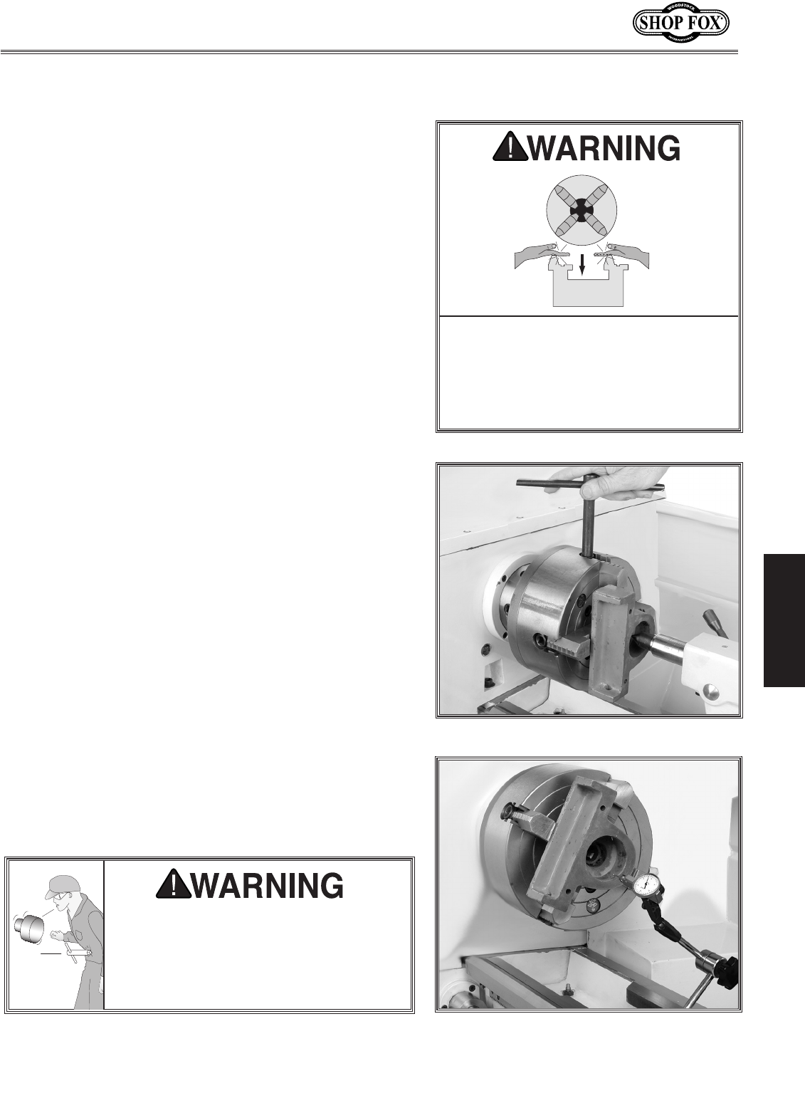
2. Lay a chuck cradle or protective layer of plywood
over the bedways to prevent your fingers from being
pinched and to protect the precision-ground surfaces
(see Figure 15).
3. Use a 14mm wrench and loosen the three hex bolts
that secure the chuck to the spindle Figure 16.
4. Support the chuck, and while anticipating the heavy
weight of the chuck, remove the three hex bolts and
then the chuck.
5. Clean the mating surfaces of the spindle and the
new chuck or faceplate with a clean oiled rag.
6. Position the other chuck or faceplate on the spindle
flange making sure it is fully seated, and tighten the
hex bolts in several alternating sequences.
PINCH HAZARD! Protect your hands
and precision ground bedways with
plywood when removing lathe/mill
chuck! The heavy weight of a fall-
ing chuck can cause serious injury.
Figure 15. Simple chuck cradle made of
scrap lumber.
Figure 16. Chuck, hex bolts, and spindle
flange.
Securely clamp your workpiece and
remove the chuck key! Thrown objects
from a lathe/mill can cause serious injury
or death to the operator and to bystand-
ers many feet away.
-16-
M1109 Combo Lathe/Mill
OPERATIONS
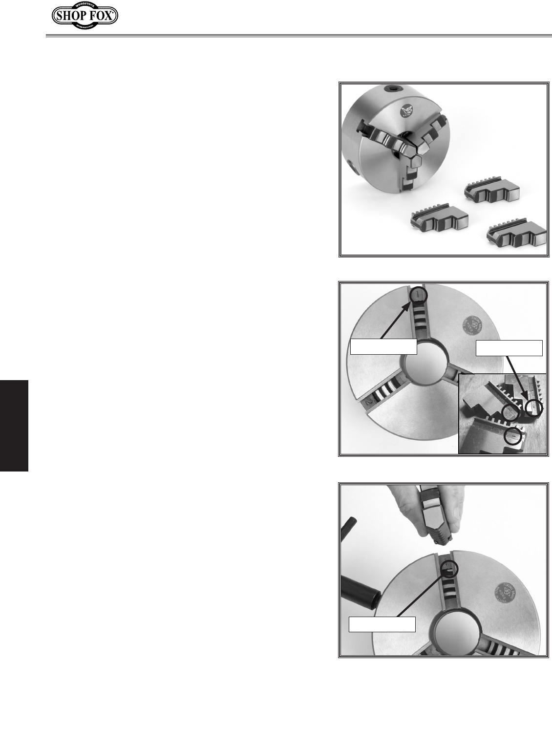
The three-jaw scroll chuck has removable hardened steel
jaws (Figure 17). The outside of the jaws are used to
hold the workpiece from the outer diameter.
Numbered from 1–3, the jaws must be used in the match-
ing numbered jaw guides, see Figure 18.
Note: The chuck need not be removed from the spindle to
swap the jaws.
To remove a set of jaws, do these steps:
1. DISCONNECT POWER TO THE LATHE/MILL!
2. Place a piece of wood over the ways to protect them
from potential damage.
3. Turn the chuck key counterclockwise and back the
jaws out.
4. Clean the jaw mating surfaces and apply a film of
white lithium grease to the mating surfaces.
5. Set the old jaws aside in a safe place free of mois-
ture and abrasives.
6. Rotate the chuck key clockwise until you see the tip
of the scroll-gear lead thread just begin to enter jaw
guide #1 (see Figure 19).
7. Insert jaw #1 into jaw guide #1 and hold the jaw
against the scroll gear.
8. Rotate the chuck key clockwise one turn to engage
the tip of the scroll-gear lead thread into the jaw.
Pull on the jaw now and it should be locked into the
jaw guide.
9. Repeat the steps on the remaining jaws.
• If installed correctly, all three jaws will converge
together at the center of the chuck.
• If the jaws do not come together, repeat this pro-
cedure until they do.
Replacing Jaws
Figure 17. Chuck and jaw selection.
Figure 18. Jaw guide number.
Figure 19. Lead thread on scroll gear.
Jaw Guide #1
Lead Thread
Jaw Numbers
-17-
M1109 Combo Lathe/Mill
OPERATIONS
Using the Four-Jaw Chuck
To install the four-jaw chuck, do these steps:
Refer to the Three-Jaw Direct Mount Scroll Chuck pro-
cedures on Page 15 to mount the four-jaw chuck.
To load a workpiece in the four-jaw chuck, do these
steps:
1. Using the chuck key, open each jaw so the
workpiece will lay flat against the chuck face.
2. Support the workpiece.
3. Lock the tailstock and then turn the tailstock quill
so the dead center makes contact or is close to the
center point of your workpiece (see Figure 20).
4. Turn each jaw until it just makes contact with the
workpiece.
5. In an opposing pattern, tighten each jaw in small
increments. After you have adjusted the first jaw,
continue tightening the opposing jaw. Check the
dead center alignment frequently to make sure
you have not wandered off your index point due to
applying too much pressure to a single jaw.
6. After the workpiece is held in place, back the
tailstock away and rotate the chuck by hand. The
center point will move if the workpiece is out of
center.
7. Make fine adjustments by slightly loosening one jaw
and tightening the opposing jaw until the workpiece
is precisely aligned. Use a dial indicator for fine tun-
ing adjustments in alignment (see Figure 21).
8. Use a lower RPM when machining heavy eccentric
workpieces.
PINCH HAZARD! Protect your hands
and precision ground bedways with
plywood when removing lathe/mill
chuck! The heavy weight of a fall-
ing chuck can cause serious injury.
Figure 20. Clamping workpiece.
Figure 21. Centering workpiece.
Securely clamp your workpiece and
remove the chuck key! Thrown objects
from a lathe/mill can cause serious injury
or death to the operator and to bystand-
ers many feet away.
-18-
M1109 Combo Lathe/Mill
OPERATIONS
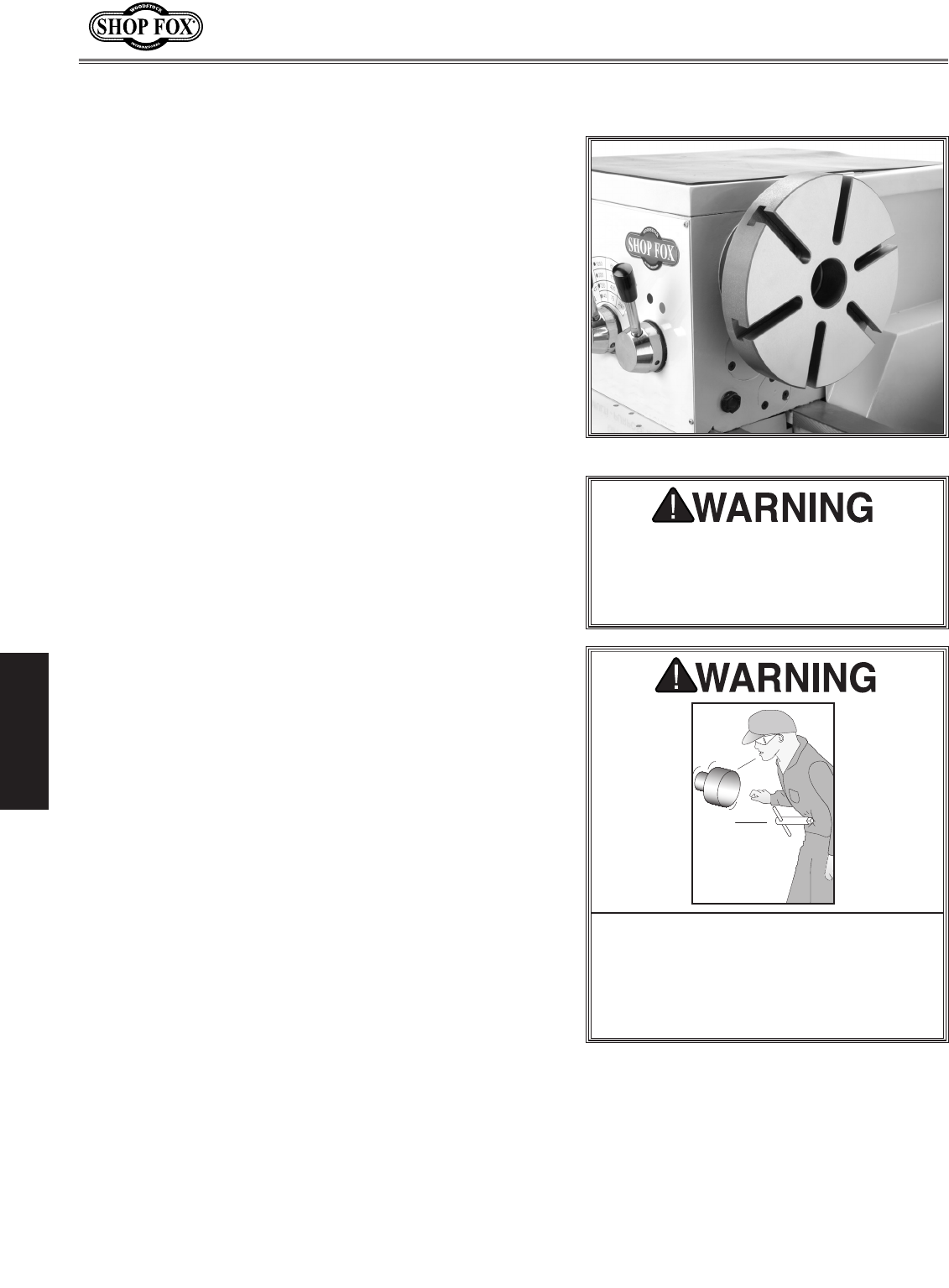
The faceplate can be used to turn non-cylindrical parts or
for off-center turning by clamping the workpiece to the
faceplate.
To install the faceplate, do these steps:
Refer to the Three-Jaw Direct Mount Scroll Chuck pro-
cedures on Page 15 to mount the faceplate.
To load a workpiece, do these steps:
1. Support the workpiece.
2. Slide the tailstock to the workpiece.
3. Lock the tailstock and then turn the tailstock quill so
the dead center makes contact with the center point
of your workpiece.
4. Lock the tailstock quill when sufficient pressure is
applied to hold the workpiece in place.
Note: Depending on the workpiece, some additional
support may be needed.
5. Secure the workpiece with a minimum of three inde-
pendent clamping devices. Failure to follow this step
may lead to deadly injury to yourself or bystanders.
Take into account rotation and the cutting forces
applied to the workpiece when clamping to the face-
plate. Make sure your clamping application will not
fail!
6. Use a lower RPM when machining heavy eccentric
workpieces.
Using the Faceplate
Figure 22. Faceplate installed.
Securely clamp your workpiece and
remove the chuck key! Thrown objects
from a lathe/mill can cause serious injury
or death to the operator and to bystand-
ers many feet away.
Use a minimum of three independent
clamping devices when turning eccentric
workpieces. Failure to provide adequate
clamping will cause workpiece to eject.
-19-
M1109 Combo Lathe/Mill
OPERATIONS
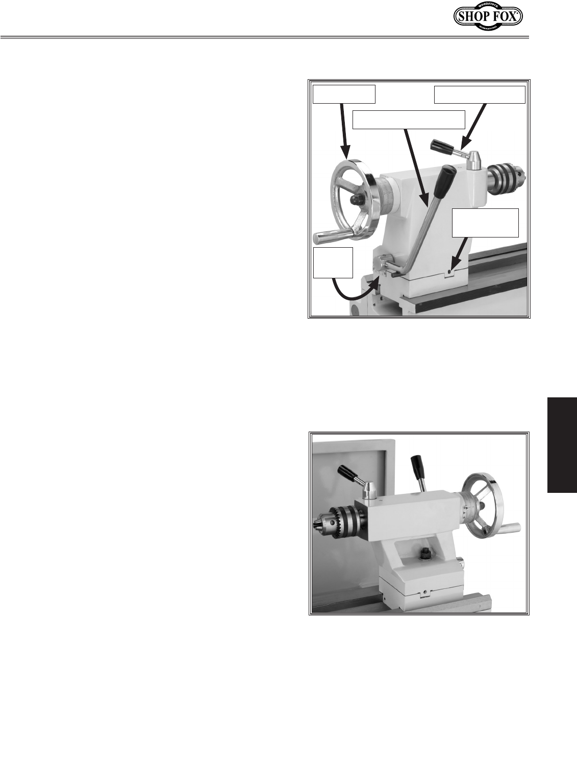
Using the Tailstock
The tailstock (Figure 23) can be used to support
workpieces with the use of a live or dead center. Using
an MT#3 drill chuck and a drill bit, the lathe can drill or
bore holes in the center of a part. The tailstock can also
be offset for cutting shallow tapers.
To use the tailstock, do these steps:
1. Slide the tailstock to the desired position.
2. Pull up on the tailstock lock lever to lock the
tailstock in place on the ways.
3. With the tailstock locked, push down the quill lock
lever to unlock.
4. Turn the quill feed handle clockwise to feed/move
the quill towards the spindle, or counterclockwise to
move away from the spindle.
5. Turn the quill lock lever to lock the quill in place.
Figure 23. Tailstock and quill lock handles
in locked position.
Tailstock Lock Lever
Drilling with the Tailstock
Quill Lock Lever
Quill Feed
Figure 24. Setting up tailstock for drilling.
To install the MT#3 drill chuck, do these steps:
1. With the tailstock locked, unlock the quill lock lever.
2. Turn the quill feed handle clockwise to extend the
quill about one inch.
3. Insert the MT#3 chuck (Figure 24) or an MT#3
tapered drill shank into the quill until the taper is
firmly seated.
4. Turn the quill feed handle clockwise to feed the drill
bit into a rotating workpiece.
5. To remove the chuck taper, turn the quill feed han-
dle counterclockwise until the chuck is pushed out of
the tailstock taper.
Offset
Scale
Offset
Adjustment
-20-
M1109 Combo Lathe/Mill
OPERATIONS
Cutting Shallow Tapers
with the Tailstock
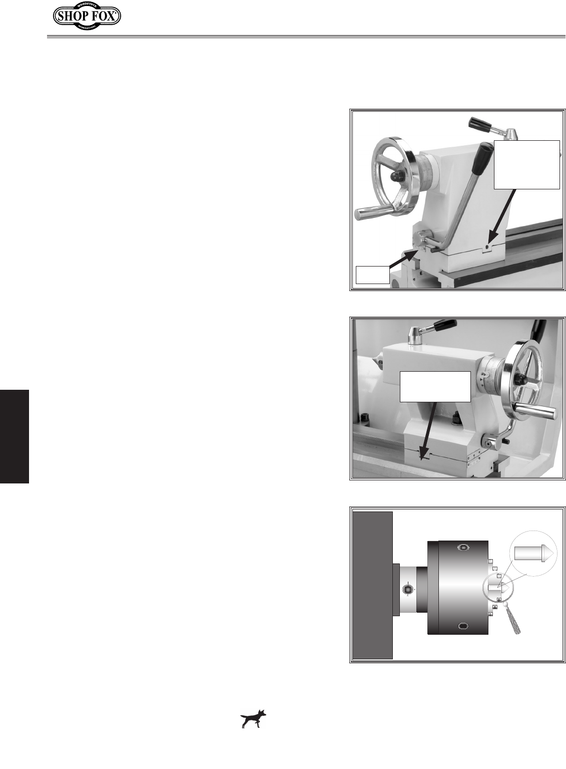
To setup the tailstock to cut tapers, do these steps:
1. Lock the tailstock in position.
2. Alternately loosen and tighten the left and right
offset adjustment screws until the desired offset is
indicated on the scale (see Figures 25 & 26).
3. Retighten the lock screw.
Note: To return the tailstock back to the original
position, repeat the process until the centered posi-
tion is indicated on the scale.
Figure 25. Right offset adjustment.
Right
Offset
Adjustment
Tailstock Alignment
The tailstock is aligned at the factory with the headstock.
We recommend that you take the time to ensure that the
tailstock is aligned to your own desired tolerances.
To align the tailstock, do these steps:
1. Using a precision level on the bedways, make sure
the lathe/mill is level side-to-side and front-to-back.
If the lathe/mill is not level, correct this condition
before proceeding.
2. Get two pieces of steel round stock, two inches in
diameter and six inches long.
3. Center drill both ends of one piece of the round
stock. Set it aside for use in Step 6.
4. Using the other piece of stock, make a dead center
by turning a shoulder to make a shank. Flip the piece
over in the chuck and turn a 60º point (see Figure
27).
Note: As long as the dead center remains in the
chuck, the point of your center will remain true to
the spindle axis. Keep in mind that the point will
have to be refinished whenever it is removed and
returned to the chuck.
Figure 26. Left offset adjustment.
Figure 27. Tailstock centering dead
center.
Continued on next page
Scale
Left Offset
Adjustments
-21-
M1109 Combo Lathe/Mill
OPERATIONS
5. Place the live center in the tailstock.
6. Attach a lathe/mill dog to the bar stock and mount
it between centers.
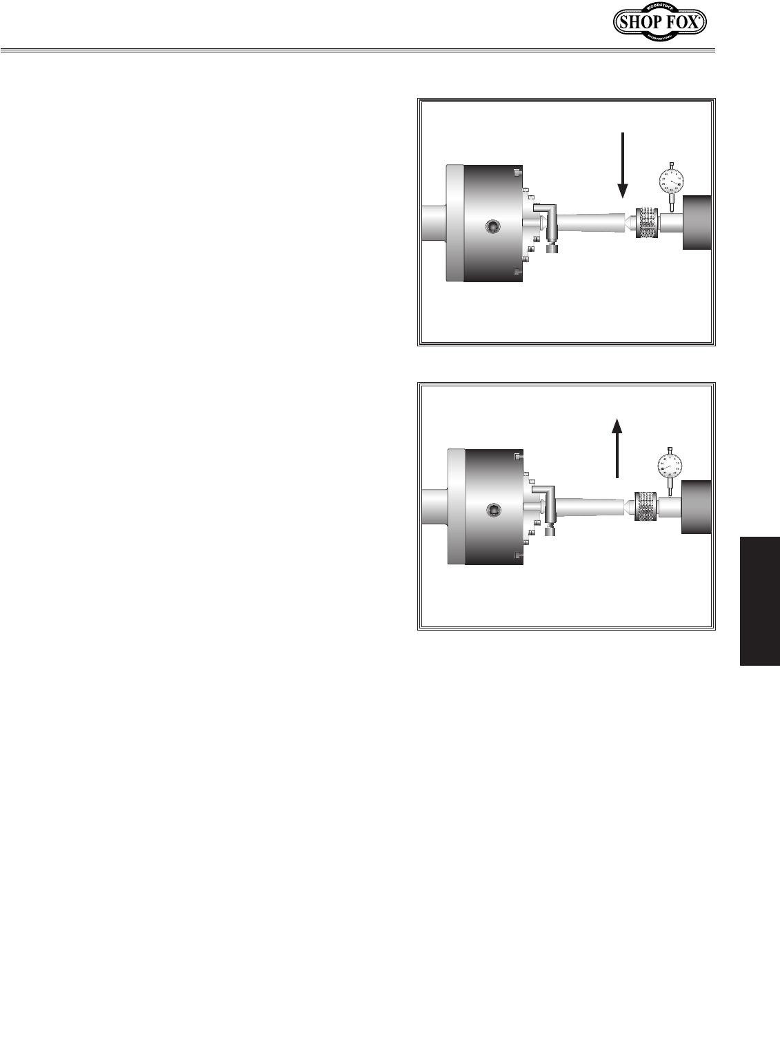
7. Turn approximately 0.010" off the diameter.
8. Measure the stock with a micrometer.
• If the stock diameter is thicker at the tailstock
end, the tailstock needs to be moved toward you
half the distance of the amount of the taper (see
Figure 28).
• If the stock diameter is thinner at the tailstock
end, the tailstock needs to be moved away from
you half the distance of the amount of the taper
(see Figure 29).
9. Mount a dial indicator so the dial plunger is on the
tailstock barrel before making adjustments to the
tailstock.
10. Turn another 0.010" off of the diameter and check
for a taper. Repeat this process as necessary until
the desired amount of accuracy is achieved.
Figure 28. Tailstock adjustment option #1.
Figure 29. Tailstock adjustment option #2.
-22-
M1109 Combo Lathe/Mill
OPERATIONS
Using Centers
The dead center is used in the tailstock and lathe spindle
to support workpieces. When used in the tailstock, make
sure to keep the MT#3 dead center tip and workpiece
lubricated to prevent tip galling.
This lathe/mill is also supplied with an MT#5 dead center
that fits into the lathe spindle taper.
To install a dead or live center, do these steps:
1. Feed the quill out about 1" and insert the MT#3 dead
center (Figure 30). The mating tapers provide the
locking action.
2. Move the tailstock into position and lock in place.
3. Feed the quill into the workpiece.
Note: Make sure there is a center drilled hole in
the end of the workpiece for the dead center.
4. Lock the quill into place once the live center and
the part rotate together. The quill may need to be
adjusted during operation.
5. To remove the dead center, retract the quill until
the dead center pops free.
To install the MT#5 dead center in the spindle, do
these steps:
1. Remove the chuck from the spindle.
2. Install the MT#5 dead center in the spindle.
3. Attach the faceplate to the spindle.
Note: When using the dead center in the spindle,
use a lathe dog so that your part will rotate with
the spindle and not spin on the dead center tip.
Figure 30. Inserting dead center.
Figure 31. Faceplate and dead center
setup.
NOTICE
Failure to keep dead center point well
lubricated will gall the dead center and
workpiece.
-23-
M1109 Combo Lathe/Mill
OPERATIONS
Using the Follow Rest
The follow rest in Figure 33 is mounted on the saddle
and follows the movement of the tool. The follow rest
requires only two fingers, as the cutting tool acts as the
third. The follow rest is used on long, slender parts to
prevent flexing of the workpiece from the pressure of the
cutting tool.
The sliding fingers are set similar to those of the steady
rest—free of play but not binding. Always lubricate during
operation. After prolonged use, the fingers will need to
be milled or filed to clean up the contact surface.
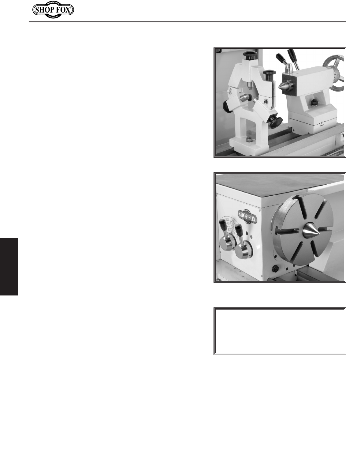
Using the Steady Rest
The steady rest serves as a support for long shafts. The
steady rest can be placed anywhere along the length of
the ways.
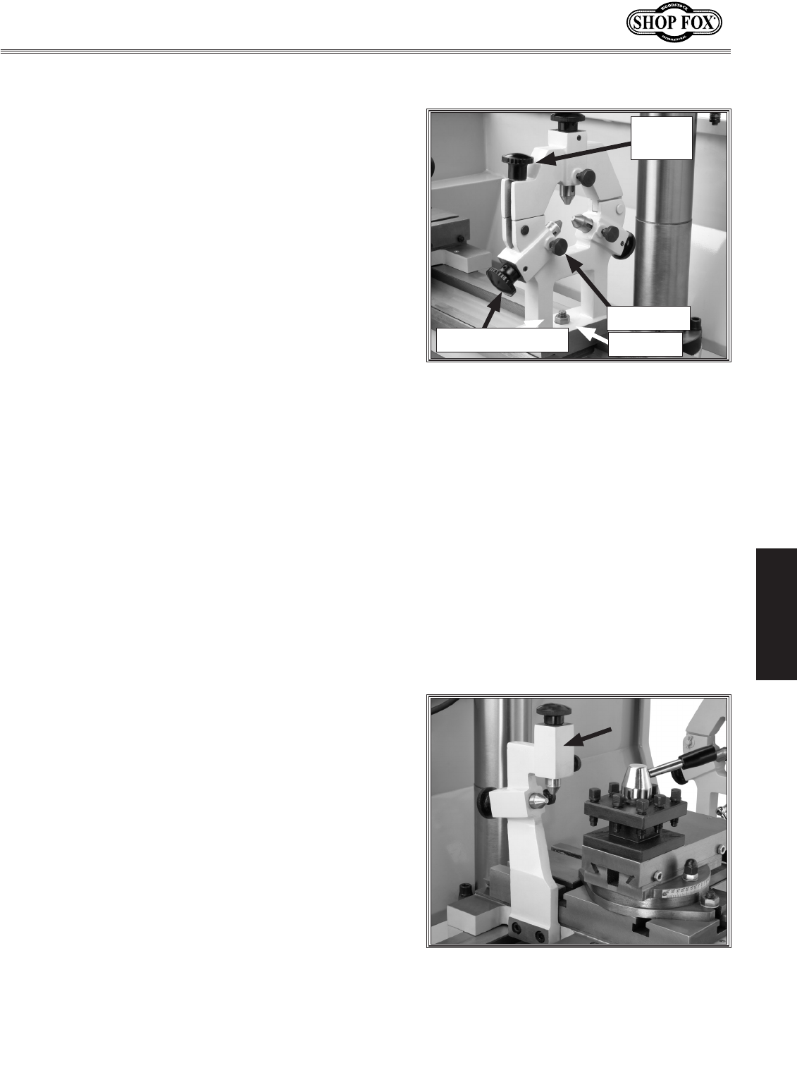
To use the steady rest, do these steps:
1. Carefully place the steady rest on the lathe bedways.
2. Loosen the lock knobs so the finger position can be
adjusted (see Figure 32).
3. Loosen the clamp knob (see Figure 32) and open the
steady rest so a workpiece can fit inside of the fin-
gers.
4. Position the steady rest where desired. Tighten the
lock nut (see Figure 32) at the base of the steady rest
to secure in place.
5. Close the steady rest so that the workpiece is inside
the fingers and tighten the clamp knob.
6. Turn the adjustment knobs so the fingers are snug
against the workpiece and then tighten the lock knobs.
Lubricate the finger tips with an anti-seize lubricant
during operation.
7. After prolonged use, the fingers will show wear. Either
mill or file the tips for a new contact surface.
Figure 32. Steady rest adjustments.
Figure 33. Follow rest attachment.
Lock Knob
Clamp
Knob
Adjustment Knob Lock Nut
-24-
M1109 Combo Lathe/Mill
OPERATIONS
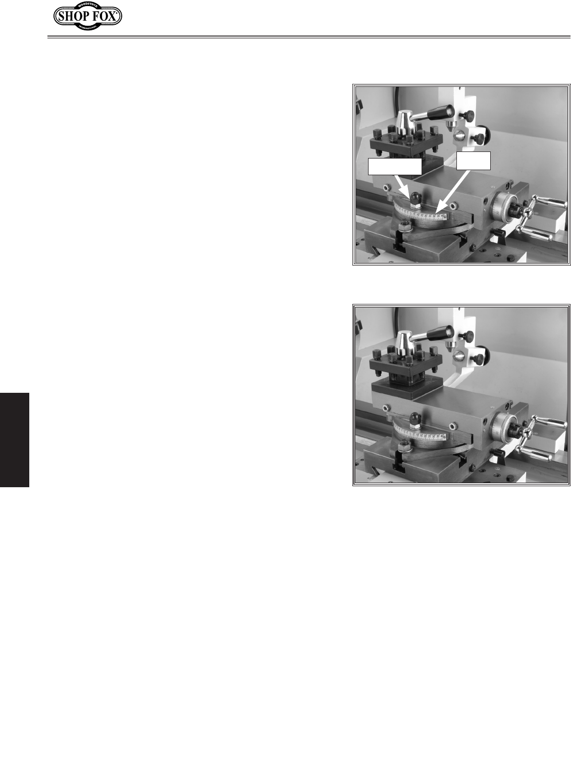
Setting Compound Slide
The compound slide is used to cut tapers on parts or to
set the proper infeed angle when threading. It may also
be used to cut specific lengths longitudinally, when set
parallel to the spindle axis.
To set the angular position, do these steps:
1. Loosen the hex nuts, one on each side of the com-
pound slide (see Figure 34).
2. Rotate the compound slide to the desired angular
position using the scale.
3. Tighten the two hex nuts. Be sure to not overtight-
en, as you may strip threads or crack or distort the
base casting.
Using the Tool Post
The four-way tool post (Figure 35) is mounted on top of
the compound slide, and allows a maximum of four tools
to be loaded simultaneously.
The four-way tool post allows for quick indexing to new
tools. This is accomplished by rotating the top handle
counterclockwise and then rotating the tool post to the
desired position. Rotate the top handle clockwise to lock
the tool into position.
Figure 34. Compound slide, scale, and
handwheel.
Figure 35. Four-way tool post.
Scale
Hex Nut

-25-
M1109 Combo Lathe/Mill
OPERATIONS
Using Manual Feed
You can manually move the cutting tool around the lathe/
mill with the three handwheels shown in Figure 36.
Longitudinal Handwheel
The longitudinal handwheel moves the carriage left or
right along the bed. This control is helpful when setting
up the machine for turning or when manual movement is
desired during turning operations.
Cross Feed Handwheel
The cross slide handwheel moves the top slide toward
and away from the work. Turning the dial clockwise
moves the slide toward the workpiece.
Compound Slide Handwheel
The compound slide handwheel controls the position of
the cutting tool relative to the workpiece. The graduated
dial is adjustable using the same method as the dial on
the cross slide. Angle adjustment is held by two hex nuts
on the base of the compound slide.
Figure 36. Carriage controls.
Cross Feed
Handwheel
Longitudinal
Handwheel
Compound
Slide
Handwheel
-26-
M1109 Combo Lathe/Mill
OPERATIONS
Setting RPM
To determine and set the needed cutting RPM, do
these steps:
1. Use the table in Figure 37 to determine the cutting
Cutting Speeds for High Speed Steel
(HSS) Cutting Tools
Workpiece Material Cutting Speed
(sfm)
Aluminum & alloys 300
Brass & Bronze 150
Copper 100
Cast Iron, soft 80
Cast Iron, hard 50
Mild Steel 90
Cast Steel 80
Alloy Steel, hard 40
Tool Steel 50
Stainless Steel 60
Titanium 50
Plastics 300-800
Wood 300-500
Note: For carbide cutting tools, double
the cutting speed. These values are a
guideline only. Refer to the MACHINERY'S
HANDBOOK for more detailed informa-
tion.
Figure 38. Spindle speed selector levers.
speed required for the workpiece material.
2. Determine the average final diameter of the
workpiece in inches, for the cut to be made.
3. Now use the following formula to determine the clos-
est RPM for the cutting operation:
(Cutting Speed x 4)
Diameter of Cut
4. With the calculated RPM, decide on the closest cut-
ting RPM to what you need.
5. Make sure the spindle is completely stopped
before proceeding.
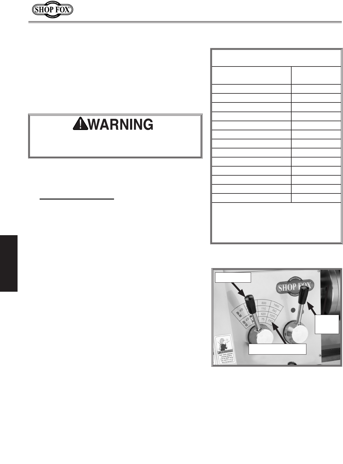
6. Move the levers (Figure 38) to get the RPM range
that is closest to your calculated RPM:
• The range lever selects BLACK DOT = High or
RED DOT = Low.
• The RPM Lever selects the RPM within that range.
Note: You may need to rotate the chuck by hand to
get the gears to engage.
RPM Lever
Figure 37. Cutting speed table for HSS
cutting tools.
= RPM
Range
Lever
Failure to follow RPM and feed rate guidelines may
threaten operator safety from ejected parts or bro-
ken tools.
RPM/Range Chart
-27-
M1109 Combo Lathe/Mill
OPERATIONS
The carriage has longitudinal and cross slide power feed
capabilities. All directions reverse when spindle rotation
is reversed.
To set and engage the power feed, do these steps:
1. DISCONNECT THE LATHE/MILL FROM POWER!
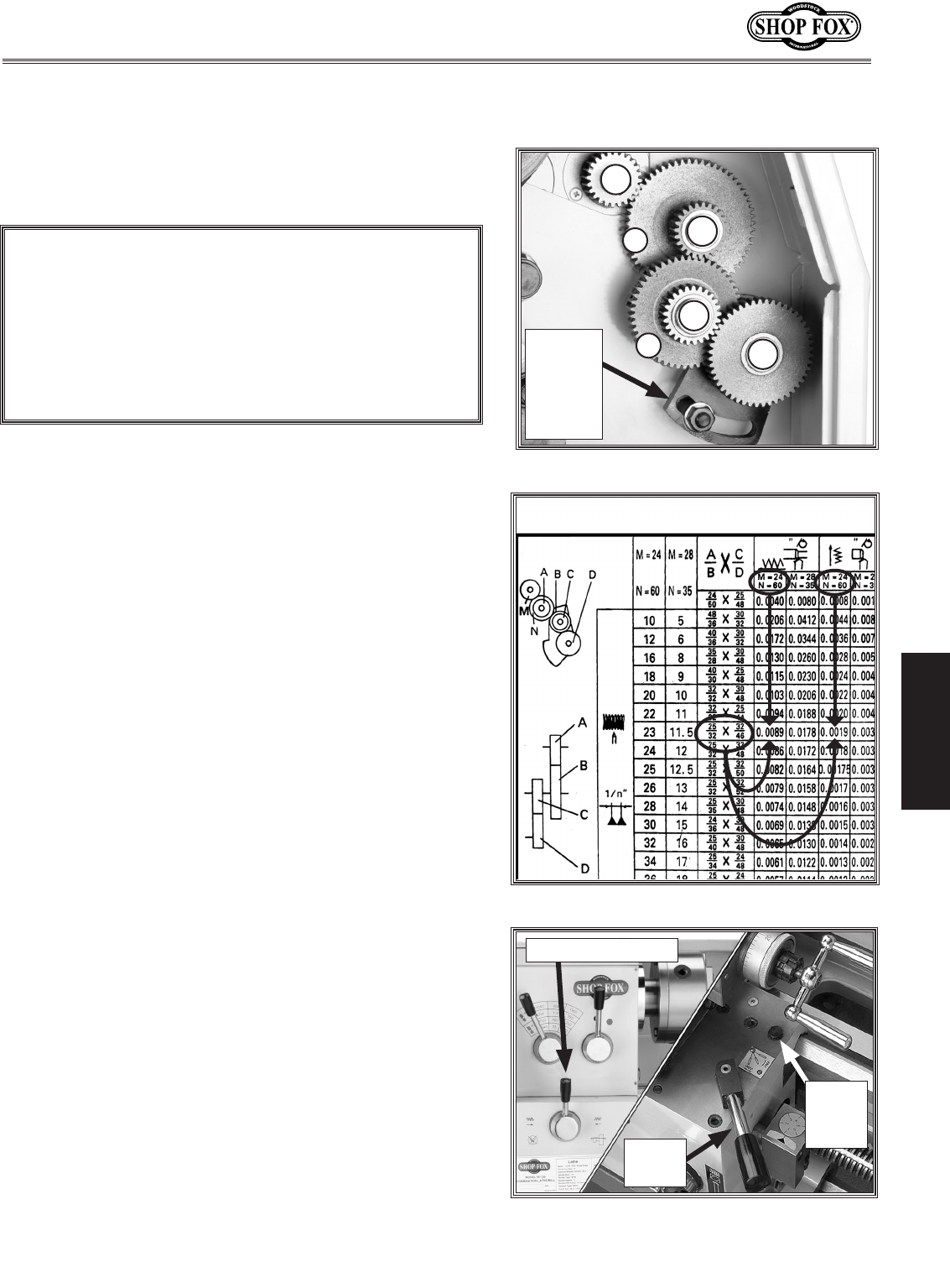
2. Refer to the Change Gear Chart on Page 29, or
the chart on the inside of the change gear door to
determine the needed combination of gears and
which spindle location to install each gear on.
See Figure 39 for the gear installation locations on
the lathe that are referenced by the chart.
See Figure 40 for examples of how certain gear
combinations can achieve your needed longitudinal
and cross feed rates. For example: The chart shows
that 0.0089" of longitudinal travel per revolution of
lead screw is needed, or 0.0019" of cross travel per
revolution of lead screw is needed.
Note: All change gears are stamped with the num-
ber of teeth they have.
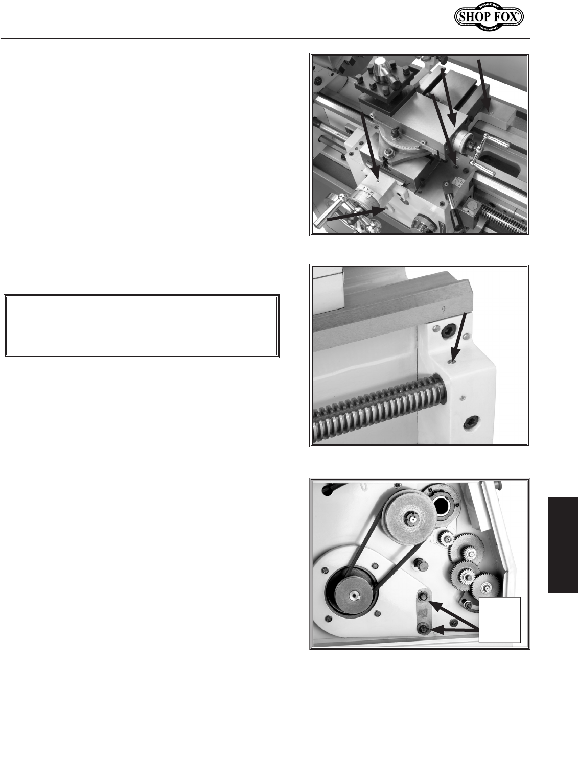
3. Loosen the lash adjuster (Figure 39) and swing the
assembly out of the way.
4. Remove the required E-clips, lubricate, and swap
out the appropriate change gears.
5. Move the lash adjuster so the gear backlash is at
0.003" to 0.008", and tighten the lock nut.
6. Use the leadscrew lever to select leadscrew rota-
tion direction (Figure 41).
7. Loosen the apron lock bolt, and use the feed lever
(Figure 41) to engage the cross feed or longitudinal
feed.
Setting Power Feed Rate
Figure 41. Leadscrew and feed levers.
Figure 39. Change gear locations.
D
C
A
B
N
M
Longitudinal
Feed
Cross
Feed
Inch
Threading
Figure 40. Using the change gear chart.
Lash
Adjuster
and
Lock
Nut
Feed
Lever
Leadscrew Lever
NOTICE
Feed rate is based on spindle RPM. High feed rates
combined with high spindle speeds result in a rapidly
moving carriage or cross slide. Pay close attention
to the feed rate you have chosen and be ready to
disengage the apron. Failure to do this may cause
the carriage to crash into the chuck.
Apron
Lock
Bolt
-28-
M1109 Combo Lathe/Mill
OPERATIONS
Your lathe is capable of cutting inch and metric threads.
To setup for threading, do these steps:
1. DISCONNECT THE LATHE/MILL FROM POWER!
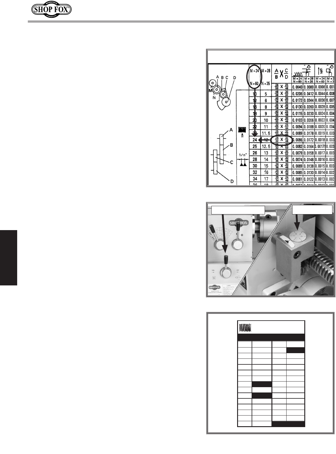
2. Refer to the Change Gear Chart on Page 29 or the
chart on the inside of the change gear door to deter-
mine the needed combination of gears and which
spindle location to install each gear on.
See Figure 42 for examples of how gear combina-
tions can achieve your needed threading rate. For
example: The chart shows that 24 TPI is needed.
Note: All change gears are stamped with the number
of teeth they have.
3. Loosen the lash adjuster (Figure 39) and swing the
assembly out of the way.
4. Remove the required E-clips, lubricate, and swap out
the appropriate change gears.
5. Move the lash adjuster so the gear backlash is at
0.003" to 0.008", and tighten the lock nut.
6. Use the leadscrew lever to select leadscrew direction
(Figure 43).
7. Setup the cutting tool, compound rest, and cross
slide to cut your threads; and loosen the apron lock
(Figure 41).
• If cutting inch threads, refer to the Thread Dial
Table in Figure 44 to use the thread dial.
• If cutting metric threads, do not use the thread
dial. Instead, you must leave the half nut engaged
until the threading operation is totally complete.
8. Loosen the apron lock bolt and use the feed lever
(Figure 41).
9. While threading, keep your hand on the half-nut
lever, ready to disengage the apron to avoid any
potential for an apron/chuck crash.
Threading Setup
Figure 43. Threading controls.
Figure 42. Using the change gear chart.
Thread Dial
Leadscrew Lever
Figure 44. Thread dial table.
5
6
7
8
9
10
11
12
13
14
15
16
17
1-6
1 or 2
1 or 2
1 or 2
1 or 2
1 or 2
1 or 2
1 or 2
1 or 2
1 or 2
1 or 2
1 or 2
1 or 2
1 or 2
1
1
1
1
1
1
1
1-6
1-6 1-6
1-6
1-6
18
20
22
23
24
25
26
28
30
32
34
36
40
48
THREAD DIAL TABLE
LEAD SCREW PITCH 5 T.P.I.
12.5
11.5
T.P.I. DIAL T.P.I. DIAL
Longitudinal
Feed
Cross
Feed
Inch
Threading
-29-
M1109 Combo Lathe/Mill
OPERATIONS
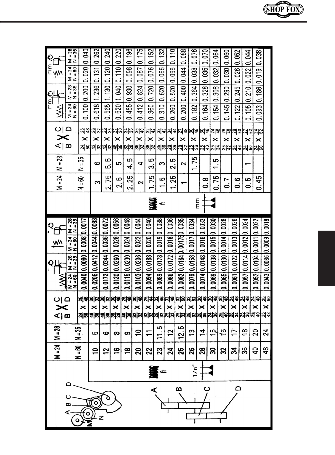
Change Gear Chart
-30-
M1109 Combo Lathe/Mill
OPERATIONS
To remove a tool from the spindle, do these steps:
1. DISCONNECT THE LATHE/MILL FROM POWER!
2. Return the headstock to the highest position and
loosen the drawbar.
3. Put on leather gloves and support the chuck or collet
and unthread the drawbar approximately four turns.
DO NOT completely unscrew the drawbar prior to
striking the drawbar or the initial threads of the
drawbar and tool will be crushed.
4. Lightly strike the drawbar with a dead blow hammer
or a piece of wood to release the arbor from the
spindle.
5. Prepair to catch the arbor, and unscrew the drawbar
until the arbor drops into your hand.
Removing Tools
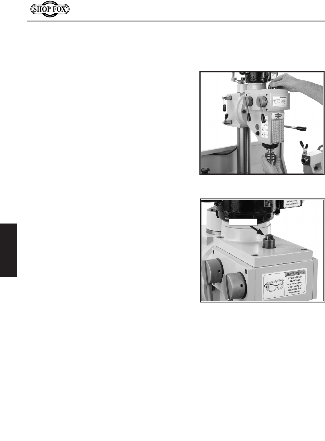
To install a tool in the spindle, do these steps:
1. DISCONNECT THE LATHE/MILL FROM POWER!
2. Carefully clean the surface of the arbor and spindle
taper. Ensure that they are free of debris and burrs.
3. Insert the arbor into the spindle, and rotate the
arbor so the slot in the arbor lines up with the pin
inside of the spindle.
4. Press the arbor up firmly to seat it with the spindle.
5. Finger tighten the drawbar into place (Figure 45),
then use a 12mm wrench to tighten the drawbar
(Figure 46).
Note: Overtightening the drawbar makes removal
difficult and stretches the threads of the arbor and
the drawbar.
6. Clear away all items from the cutting tool before
turning the mill ON.
Installing Tools
Figure 45. Aligning drawbar with chuck
arbor.
MILLING OPERATIONS
Figure 46. The drawbar.
Drawbar
-31-
M1109 Combo Lathe/Mill
OPERATIONS
Figure 48. Headstock handle.
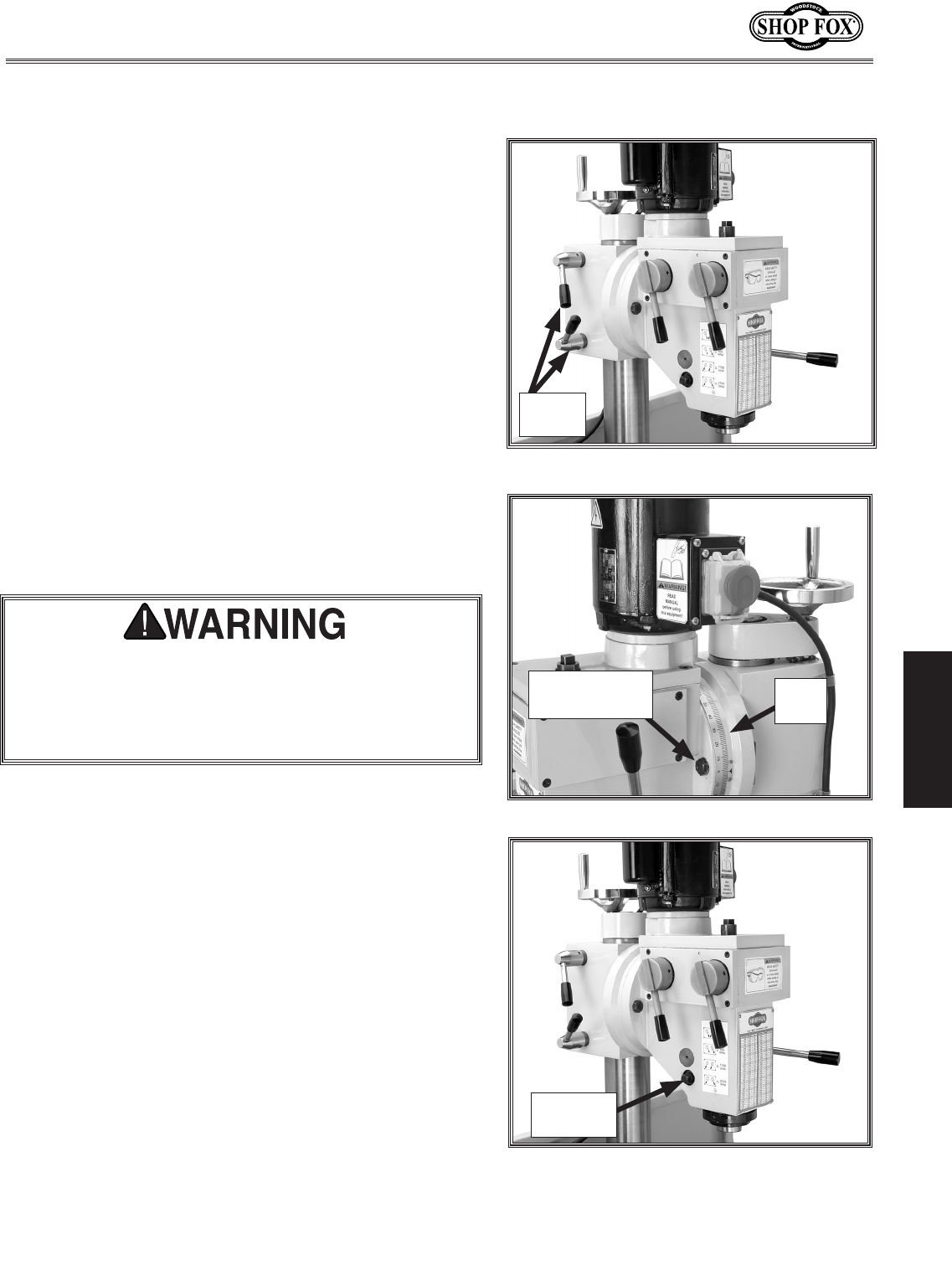
The quill feed is controlled by the handle on the right
of the headstock, and a lock bolt on the left side of the
headstock (Figure 49).
To use the quill, do these steps:
1. Unlock the quill feed lock bolt to release the quill.
2. For drilling, pull the handle toward you and the quill
will feed down toward the workpiece.
Note: The quill feed handle is spring loaded so that
it will automatically return to its upmost vertical
position. DO NOT let go of the handle at the end of
an operation to prevent damage to the quill.
3. For milling, hold the quill at a particular depth and
tighten the quill lock bolt.
Figure 49. Quill lock.
Quill Travel
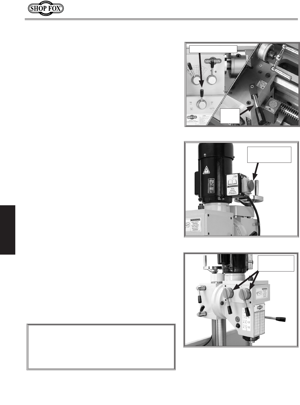
The mill headstock head can be raised and lowered verti-
cally, or rotated left or right up to 90º degrees to position
the cutting tool next to the workpiece.
To position the spindle head vertically, do these steps:
1. Make sure the spindle is stopped and the work area
is free from obstructions before proceeding.
2. Loosen both column lock levers so that the head-
stock can freely slide on the column (Figure 47).
3. Rotate the mill height handwheel (Figure 47) to
raise or lower the headstock to the desired position
then lock the levers.
4. While supporting the headstock, use a 17mm wrench
and loosen both left and right headstock tilt lock
nuts (Figure 47), then tilt the headstock to your
desired angle. Retighten the lock nuts.
Headstock Positioning
Figure 47. Headstock lock levers.
Headstock
Tilt Lock Nut
Lock
Levers
Tilt
Scale
The headstock is heavy. Make sure that you sup-
port the headstock before you loosen the lock nuts.
Ignoring this warning may allow the headstock to
uncontrollably swing over to the right or left causing
injury or severe lathe/mill damage.
Quill
Lock Bolt
-32-
M1109 Combo Lathe/Mill
OPERATIONS
Figure 50. Headstock and apron controls.
Figure 51. Start switch location.
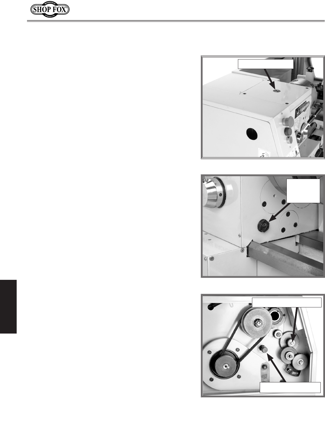
Table Travel
The mill table of the Model M1109 can be moved in two
axes—cross feed and longitudinal feed. Each of these axes
are controlled by graduated handwheels to accurately
position the workpiece in relation to the tool. To set the
power feed for milling, refer to Setting Power Feed Rate
on Page 27.
Cross Feed
The cross feed is controlled by the cross feed handwheel
of the lathe shown in Figure 50.
Longitudinal Feed Control
The longitudinal feed is controlled by the longitudinal
handwheel of the lathe, and the lock at the back of the
saddle (see Figure 50).
Start Up and Spindle
Break-in Procedures
Figure 52. Gearbox and controls.
Mill Spindle
ON/OFF Switch
NOTICE
Failure to follow start up and spindle break-in pro-
cedures will cause rapid deterioration of spindle and
other related parts, and never shift gears while lathe
or mill is running.
It is essential to closely follow the proper break-in pro-
cedures to ensure trouble free performance. Complete
this process once you have familiarized yourself with all
instructions in this manual.
To begin the start up procedure, do these steps:
1. Make sure the mill has been properly lubricated.
2. Make sure there are no obstructions around or
underneath the spindle.
3. Set the spindle speed to 240 RPM.
4. Turn the mill ON (Figure 51).
5. Turn the spindle ON and run it a minimum of 10
minutes. Repeat this step on the other three RPM
ranges.
Feed
Lever
Leadscrew Lever
Milling Speed
Levers

-33-
M1109 Combo Lathe/Mill
OPERATIONS
Setting RPM
When using the milling machine, determine the RPM
needed to cut your workpiece, and adjust the gear
change levers to achieve the closest RPM.
NOTICE
Never shift gears while lathe or mill is running; other-
wise, the gear teeth will be chipped or broken.
To determine and set the mill to the needed RPM, do
these steps:
1. Select the cutting speed required for the material of
your workpiece using the table in Figure 37.
2. Measure the diameter of your cutting tool in inches.
3. Use the following formula to determine the needed
RPM for your operation:
(Cutting Speed x 4) / Tool Diameter = RPM
Note: You will only be able to get an approximate
RPM value with the variable speed knob.
4. Move the mill gearbox levers to the nearest milling
speed RPM.
Cutting Speeds for High Speed Steel (HSS)
cutting tools:
Workpiece Material Cutting Speed (sfm)
Aluminum & alloys 300
Brass & Bronze 150
Copper 100
Cast Iron, soft 80
Cast Iron, hard 50
Mild Steel 90
Cast Steel 80
Alloy Steel, hard 40
Tool Steel 50
Stainless Steel 60
Titanium 50
Plastics 300-800
Wood 300-500
Figure 37. High speed steel cutting chart.
Note: Double the cutting speed for carbide
cutting tools. These values are a guideline
only. Refer to the MACHINERY'S HANDBOOK
for more detailed information.
NOTICE
Failure to follow RPM and Feed Rate
Guidelines will put undue strain on
moving parts, shorten tool life, poor
workpiece results and may threaten
operator safety from ejected parts or
broken tools.
-34-
M1109 Combo Lathe/Mill
MAINTENANCE
MAINTENANCE
Regular periodic maintenance of your lathe/mill will
ensure optimum performance. Make a habit of inspecting
your machine each time you use it.
Check for the following conditions and repair or
replace when necessary:
• Loose mounting bolts and chuck.
• Worn switch or safety features.
• Worn or damaged cords and plugs.
• Any other condition that could hamper the safe
operation of this machine.
Clean your machine every day or more often as needed.
Make sure to unplug the lathe/mill before cleaning it.
Never blow the lathe/mill off with compressed air, oth-
erwise you will force metal shavings deep into mecha-
nisms. Remove chips as they accumulate with rags,
brushes, and a shop vacuum. Chips left on the machine
soaked with water-based coolant will eventually invite
oxidation and a gummy residue build up around moving
parts. Cleaning will help keep your lathe/mill running
smoothly. Always be safe and responsible with the use
and disposal of cleaning products.
Never use acetone, gasoline, or lacquer thinner to
remove stains or oil from painted surfaces. These chemi-
cals will melt the paint. Use mineral spirits or mild
household degreasers.
General Cleaning
General Maintenance
General Lubrication
Keep the headstock oil level at 3⁄4 full (Figure 54). After
break-in, change the oil in the headstock with Mobil® DTE®
Heavy-Medium or an equilivant grade of oil immediately
and then again after three months. After that, change the
oil at the same time on an annual basis or more frequent-
ly if extreme machine use requires it.
To control surface rust on machined surfaces, wipe the
unprotected metal as required with a rust inhibiting oil.
Paint all gears in Figure 55 with a good quality automo-
tive wheel bearing grease as required to keep lubricated.
Figure 55. Headstock and gear box drain
locations.
Figure 54. Headstock oil level sight glass.
Figure 53. Headstock fill plug.
Headstock
Oil Level
Sight Glass
Gear Spindle Ball Oiler
Headstock Oil Drain
Headstock Oil Fill
-35-
M1109 Combo Lathe/Mill
MAINTENANCE
For daily lubrication, use a manual oil gun with a general
10W machine oil to lubricate the following 15 ball oiler fit-
tings. See Figure 56 for some typical locations. Wipe off
all oil ball fittings with a rag, and then oil the following
locations:
• Cross Feed Table (1 ball oiler on top)
• Cross Feed Handwheel (1 ball oiler on top)
• Saddle Ways (2 ball oilers on top)
• Apron Handwheel Gear Axle (1 ball oiler on apron face)
• Compound Rest (1 ball oiler on top)
• Tailstock Barrel (1 ball oiler on top)
• Tailstock Handwheel (1 ball oiler on right side)
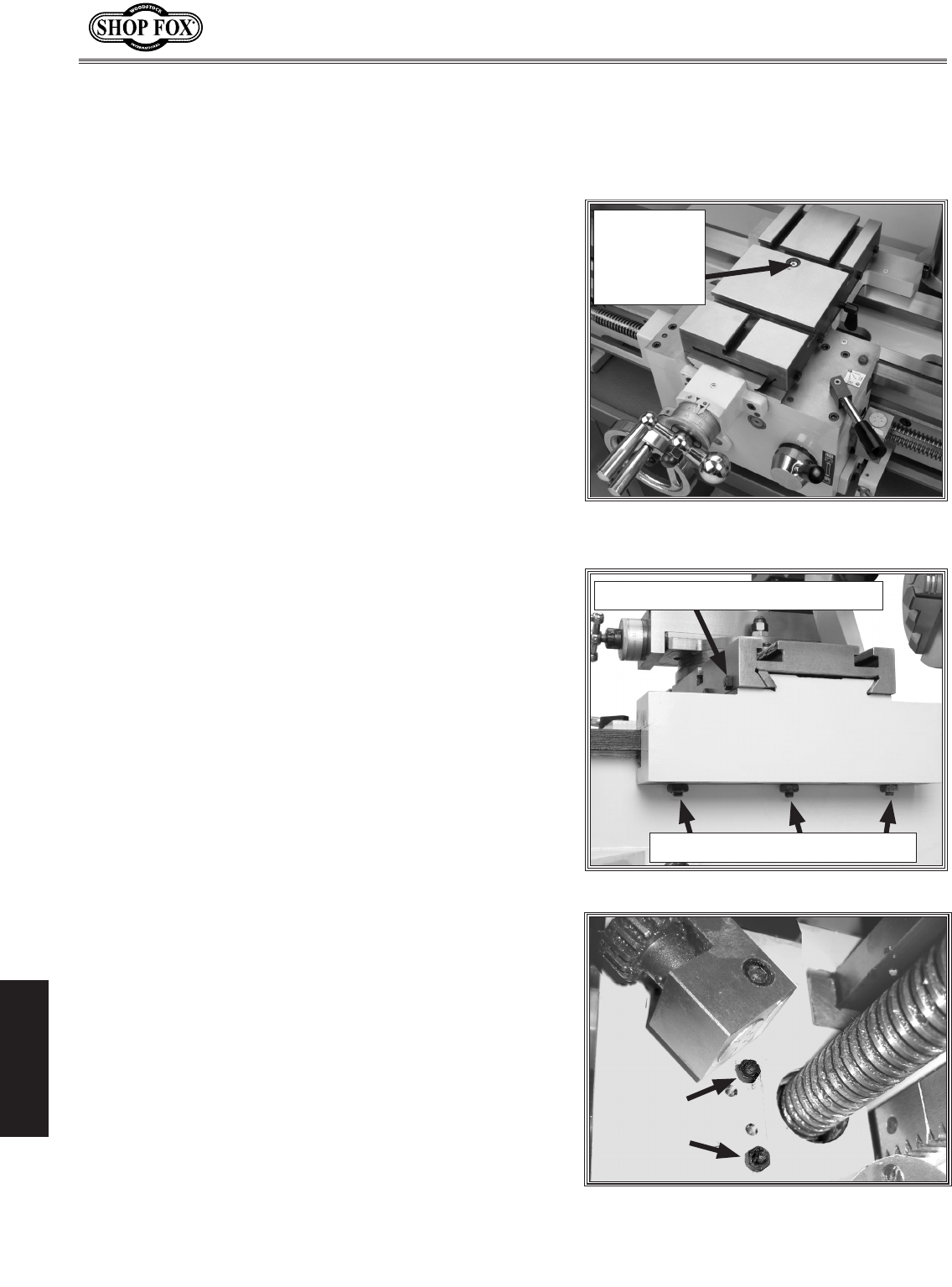
• Lead Screw Endcap Bushing (1 ball oiler, see Figure 57)
• Change Gear Spindle (1 ball oiler on end of shaft)
• Gear Spindle Ball Oiler (1 ball oiler, see Figure 55)
• Gearbox (4 ball oilers on top)
Figure 56. Typical ball fitting locations.
Failure to follow lubrication guidelines will lead
to rapid deterioration of lathe/mill components.
NOTICE
Figure 57. Lead screw end cap bushing.
Figure 58. Motor mount bolts.
Adjusting/Replacing
the V-Belt
To replace or adjust the V-belts, do these steps:
1. DISCONNECT POWER TO THE LATHE/MILL!
2. Open the change gear access door (Figure 58).
3. Loosen the four motor access cover screws, and lift
the cover off (Figure 58).
4. Using a 17mm wrench, loosen the two motor mount
bolts shown in Figure 58.
5. Grasp the motor and lift upward to de-tension the
belt and remove the belt.
6. Use solvent to clean the pulleys of oil and install the
new belt.
7. Let the motor hang to tension the belt, and tighten
the two motor mount bolts.
8. Close the access door and latch it shut.
Motor
Mount
Bolts
-36-
M1109 Combo Lathe/Mill
SERVICE
SERVICE
Figure 59. Cross slide backlash
adjustment cap screw.
Figure 60. Gib adjustment points.
Cross Feed
Backlash
Adjustment
Cap Screw
Saddle Gib Adjustment Points
Cross Slide Gib Adjustment Point
Figure 61. Half-nut gib adjustment
location (thread dial is swung out of the
way for gib adjustment).
Cross Slide Backlash
Backlash is the amount of play found in a lead screw.
It can be found by turning the cross slide handwheel in
one direction, and then turning the handwheel the other
direction. When the cross slide begins to move, the back-
lash has been taken up.
Note: Avoid the temptation to overtighten the cross slide
backlash screw. Overtightening will cause excessive wear
to the sliding block and lead screw.
Backlash is adjusted by tightening or loosening the screw
shown in Figure 59. This screw draws a wedge-type nut
against the lead screw and main nut. If you get it too
tight, loosen the screw a few turns and tap the cross feed
a few times with a rubber or wooden mallet. Then turn
the handle slowly back and fourth until the handle turns
freely. To readjust the backlash, rock the handle back and
fourth and tighten the screw slowly until the backlash
is at approximately 0.001" to 0.002" as indicated on the
handwheel dial.
Note: Reducing backlash to less than 0.001" is impractical
and reduces the life of the cross slide.
Cross Slide, Half-Nut,
and Compound Slide Gib
Adjustments
When adjusting these gibs (Figures 60 and 61), keep in
mind that the goal is to remove sloppiness in the ways
without causing the slides or half nut to bind. Loose gibs
will cause a poor finish on the workpiece and may cause
undue wear on the slide. Over-tightening may cause pre-
mature wear on the slide, lead screw, and half-nut. The
cross slide gib is a tapered piece of iron. When the oppos-
ing front and rear gib adjustment screws are turned in
opposing directions, the screws force the tapered gibs to
fill the loose void in the way, thus tightening the play in
the cross slide. If more play is needed turn the screws the
other direction.
For the four saddle gibs, (Figure 60) loosen the jam nuts
and turn the three set screws until there is slight tension
felt and the gib plates are slightly preloaded against the
underside of the flat-way. Tighten the jam nuts when fin-
ished.
-37-
M1109 Combo Lathe/Mill
SERVICE
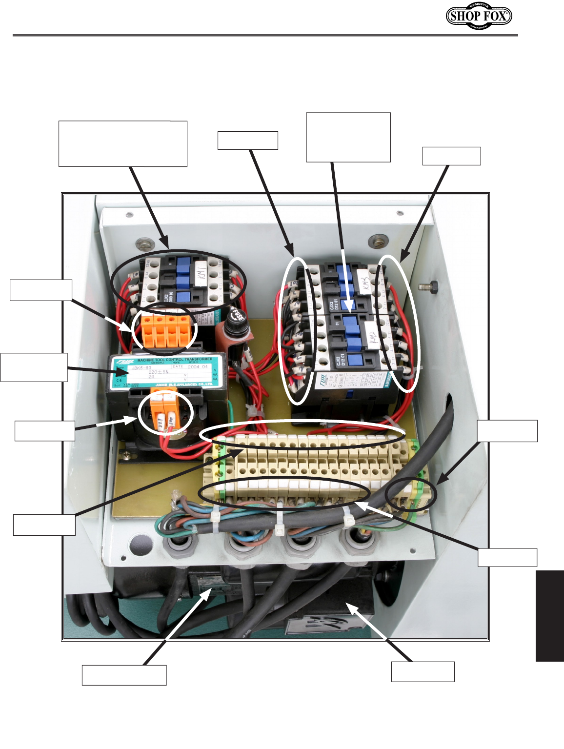
Electrical Component and Connection Index
Figure 62. M1109 Electrical panel.
(TC)
Transformer
Figure 72
Figure 66
Figure 73
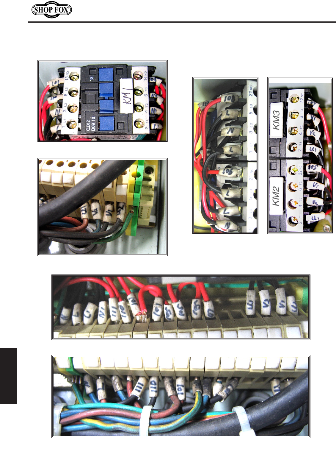
(KM1)
Main System Contactor
See Figure 63
(KM2, KM3)
Spindle Motor
Direction
Contactors
Spindle Motor Figure 69
Figure 64
Figure 68
Figure 65
(This page is available online in color at: www.shopfoxtools.com)
Figure 67
-38-
M1109 Combo Lathe/Mill
SERVICE
Figure 67. Junction block wiring.
Electrical Connections
Figure 66. Junction block wiring.
Figure 64. Junction block wiring.
Figure 65. Contactor
wiring (KM2 and KM3).
Figure 68. Contactor
wiring (KM2 and KM3).
Figure 63. Contactor wiring (KM1).
(This page is available online in color at: www.shopfoxtools.com)
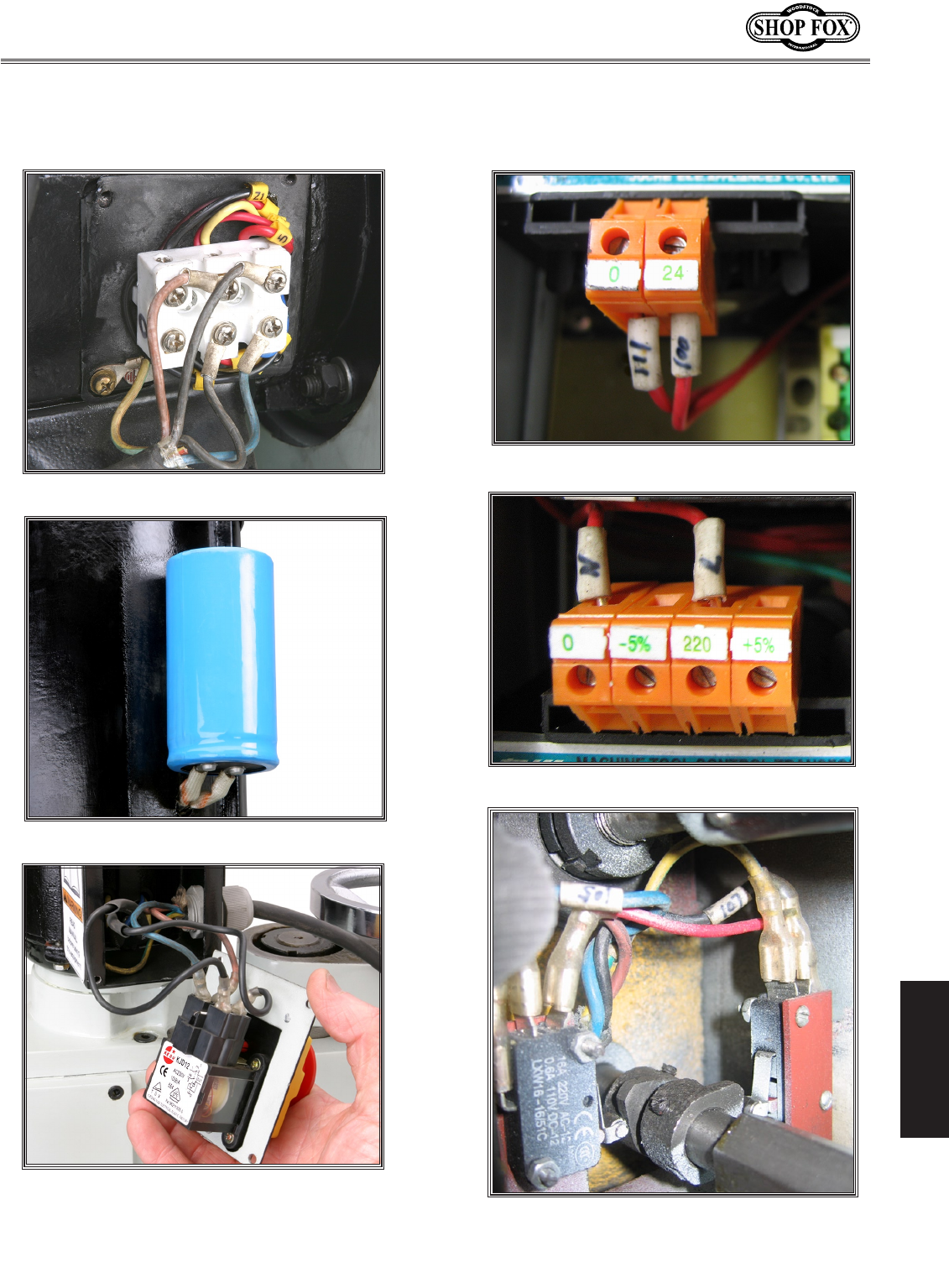
-39-
M1109 Combo Lathe/Mill
SERVICE
Electrical Connections
Figure 71. Mill power switch.
Figure 70. Start capacitor.
Figure 69. Motor connection.
Figure 73. Transformer connection.
Figure 72. Transformer connection.
(This page is available online in color at: www.shopfoxtools.com)
Figure 74. Lathe motor direction limit
switches.
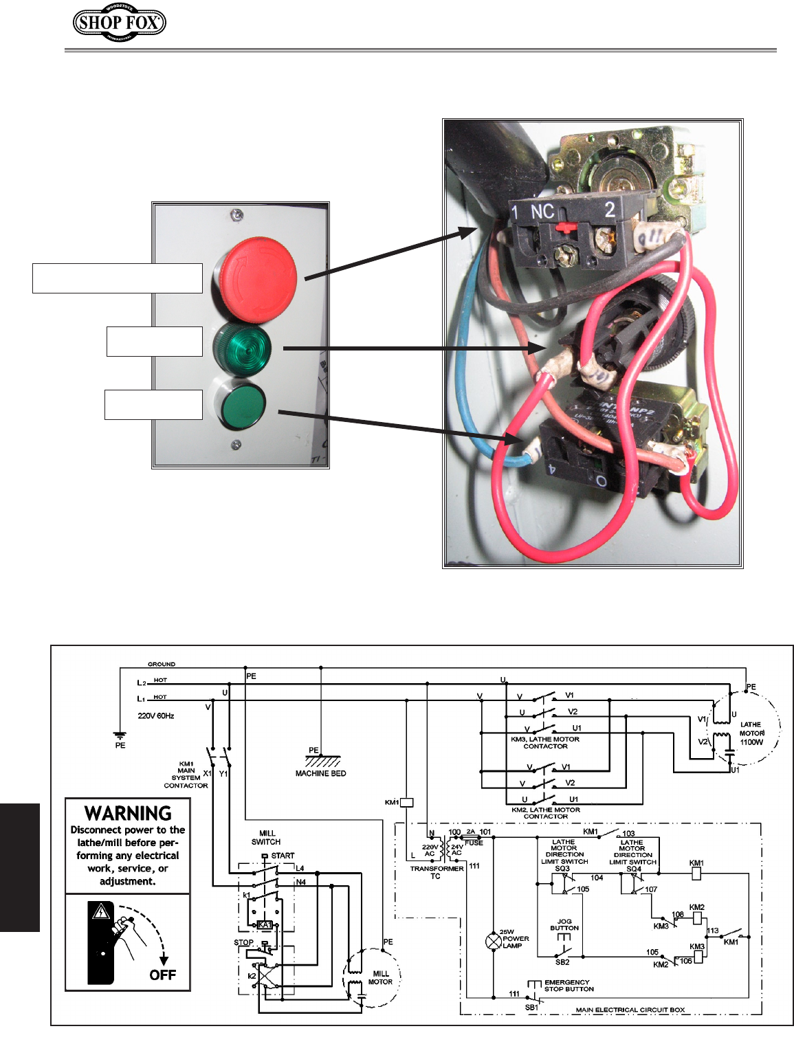
-40-
M1109 Combo Lathe/Mill
SERVICE
Wiring Diagram
Figure 76. Lathe control panel wiring.
Figure 75. Lathe controls.
Emergency Stop Switch
Power Lamp
Jog Button
Electrical Connections

-41-
M1109 Combo Lathe/Mill
SERVICE
SYMPTOM POSSIBLE CAUSE CORRECTIVE ACTION
Motor will not
start.
1. Incorrect lathe operation.
2. Main power switch is OFF.
3. Emergency switch is pushed in.
4. Circuit breaker or fuse is at fault.
5. No voltage or open connection.
6. Motor is at fault.
1. Use the spindle direction ON/OFF lever.
2. Turn the main power switch ON at the back of the
lathe.
3. Rotate emergency switch so it pops out.
4. Seek an electrician to troubleshoot and repair the
shop power supply.
5. Test circuit, replace wires and connections as
required.
6. Replace motor.
Fuses or circuit
breakers trip
open.
1. Short circuit in line cord or plug.
2. Short circuit in motor or loose connections.
3. Incorrect fuses or circuit breakers in power
supply.
1. Inspect cord or plug for damaged insulation and
shorted wires.
2. Inspect all connections on motor for loose or
shorted terminals or worn insulation.
3. Install correct fuses or circuit breakers.
Carriage hard to
move.
1. Chips have loaded up on bedways.
2. Bedways are dry and in need of lubrication.
3. Longitudinal stops are interfering.
4. Gibs are too tight.
1. Frequently clean away chips that load up during
turning operations.
2. Lubricate bedways and handles.
3. Check to make sure that stops are floating and not
hitting the center stop.
4. Loosen gib screw(s) slightly.
Machine is loud
when cutting.
Overheats or
bogs down in the
cut.
1. Excessive depth of cut.
2. RPM or Feed Rate wrong for operation.
3. Dull cutters.
1. Decrease depth of cut.
2. Refer to RPM Feed rate chart for appropriate rates.
3. Sharpen or replace cutters.
Bad surface fin-
ish.
1. Wrong RPM or feed rate.
2. Dull tooling or tool not centered correctly.
3. Too much play in gibs.
1. Adjust for appropriate RPM and feed rate.
2. Sharpen tooling and/or center tool correctly.
3. Tighten gibs.
Gear change
levers will not
shift into posi-
tion.
1. Gears not aligned in headstock. 1. Rotate spindle by hand until gear falls into place.
Can't remove
tapered tool
from quill.
1. Quill had not retracted all the way back into
the tailstock.
1. Turn the quill handwheel until it forces taper out
of quill.
Troubleshooting
This section covers the most common lathe problems. DO NOT make any adjustments until the lathe is
disconnected from power and all moving parts have come to a complete stop.
Motor & Electrical

-42-
M1109 Combo Lathe/Mill
SERVICE
SYMPTOM POSSIBLE CAUSE CORRECTIVE ACTION
Entire machine
vibrates exces-
sively upon
startup and while
running.
1. Workpiece is unbalanced.
2. Worn or broken gear present.
3. Chuck or faceplate has become unbalanced.
4. Spindle bearings badly worn.
1. Reinstall workpiece so it is as centered with the
spindle bore as possible.
2. Inspect gears and replace if necessary.
3. Rebalance chuck or faceplate; contact a local
machine shop for help.
4. Replace spindle bearings.
Bad surface fin-
ish.
1. Wrong RPM or feed rate.
2. Dull tooling or poor tool selection.
3. Too much play in gibs.
4. Tool too high.
1. Adjust for appropriate RPM and feed rate.
2. Sharpen tooling or select a better tool for the
intended operation.
3. Tighten gibs.
4. Lower the tool position.
Can't remove
tapered tool
from tailstock
quill.
1. Quill had not retracted all the way back into
the tailstock.
2. Debris was not removed from taper before
inserting into quill.
1. Turn the quill handwheel until it forces taper out
of quill.
2. Always make sure that taper surfaces are clean.
Cross slide, com-
pound slide, or
carriage feed has
sloppy operation.
1. Gibs are out of adjustment.
2. Handwheel is loose.
3. Lead screw mechanism worn or out of adjust-
ment.
1. Tighten gib screw(s).
2. Tighten handwheel fasteners.
3. Tighten any loose fasteners on lead screw mecha-
nism.
Cross slide, com-
pound slide, or
carriage feed
handwheel is
hard to move.
1. Gibs are loaded up with shavings, dust, or
grime.
2. Gib screws are too tight.
3. Backlash setting too tight (cross slide only).
4. Bedways are dry.
1. Remove gibs, clean ways/dovetails, lubricate, and
readjust gibs.
2. Loosen gib screw(s) slightly, and lubricate
bedways.
3. Slightly loosen backlash setting by loosening the
locking screw and adjusting the spanner ring at the
end of the handle.
4. Lubricate bedways and handles.
Cutting tool or
machine com-
ponents vibrate
excessively dur-
ing cutting.
1. Tool holder not tight enough.
2. Cutting tool sticks too far out of tool holder;
lack of support.
3. Gibs are out of adjustment.
4. Dull cutting tool.
5. Incorrect spindle speed or feed rate.
1. Check for debris, clean, and retighten.
2. Reinstall cutting tool so no more than 1/3 of the
total length is sticking out of tool holder.
3. Tighten gib screws at affected component.
4. Replace or resharpen cutting tool.
5. Use the recommended spindle speed.
Inaccurate turn-
ing results from
one end of the
workpiece to the
other.
1. Headstock and tailstock are not properly
aligned with each other.
1. Realign the tailstock to the headstock spindle bore
center line.
Chuck jaws won't
move or don't
move easily.
1. Chips lodged in the jaws. 1. Remove jaws, clean and lubricate chuck threads,
and replace jaws.
Carriage won't
feed.
1. Gears are not all engaged.
2. Gears are broken.
3. Loose screw on the feed handle.
1. Adjust gear positions.
2. Replace.
3. Tighten.
Operation and Work Results

-43-
M1109 Combo Lathe/Mill
SERVICE
SYMPTOM POSSIBLE CAUSE CORRECTIVE ACTION
Loud, repetitious
noise coming
from machine
at or near the
motor.
1. Pulley setscrews or keys are missing or loose.
2. Motor fan is hitting the cover.
1. Inspect keys and setscrews. Replace or tighten if
necessary.
2. Tighten fan or shim cover, or replace items.
Carriage hard to
move.
1. Carriage lock is tightened down.
2. Chips have loaded up on bedways.
3. Bedways are dry and in need of lubrication.
4. Longitudinal stops are interfering.
5. Gibs are too tight.
1. Check to make sure table locks are fully released.
2. Frequently clean away chips that load up during
turning operations.
3. Lubricate bedways and handles.
4. Check to make sure that stops are floating and not
hitting the center stop.
5. Loosen gib screw(s) slightly.
Gear change
levers will not
shift into posi-
tion.
1. Gears not aligned in headstock. 1. Rotate spindle by hand until gear falls into place.
Motor overheats. 1. Motor overloaded.
2. Air circulation through the motor restricted.
1. Reduce load on motor.
2. Clean out motor to provide normal air circulation.
Loud, repetitious
noise coming
from machine.
1. Gears not aligned in headstock or no back-
lash.
2. Broken gear or bad bearing.
3. Workpiece is hitting stationary object.
1. Adjust gears and establish backlash.
2. Replace broken gear or bearing.
3. Stop lathe immediately and correct interference
problem.
Tailstock quill
will not feed out
of tailstock.
1. Quill lock lever is tightened down. 1. Turn lever counterclockwise.
Motor is loud
when cutting.
Overheats or
bogs down in the
cut.
1. Excessive depth of cut or feed rate.
2. RPM or feed rate wrong for cutting
operation.
3. Cutting tool is dull.
4. Gear setup is too tight, causing them to
bind.
1. Decrease depth of cut or feed rate.
2. Refer to RPM feed rate chart for appropriate rates.
3. Sharpen or replace the cutting tool.
4. Readjust the gear setup with a small amount of
backlash so the gears move freely and smoothly
when the chuck is rotated by hand.
PARTS
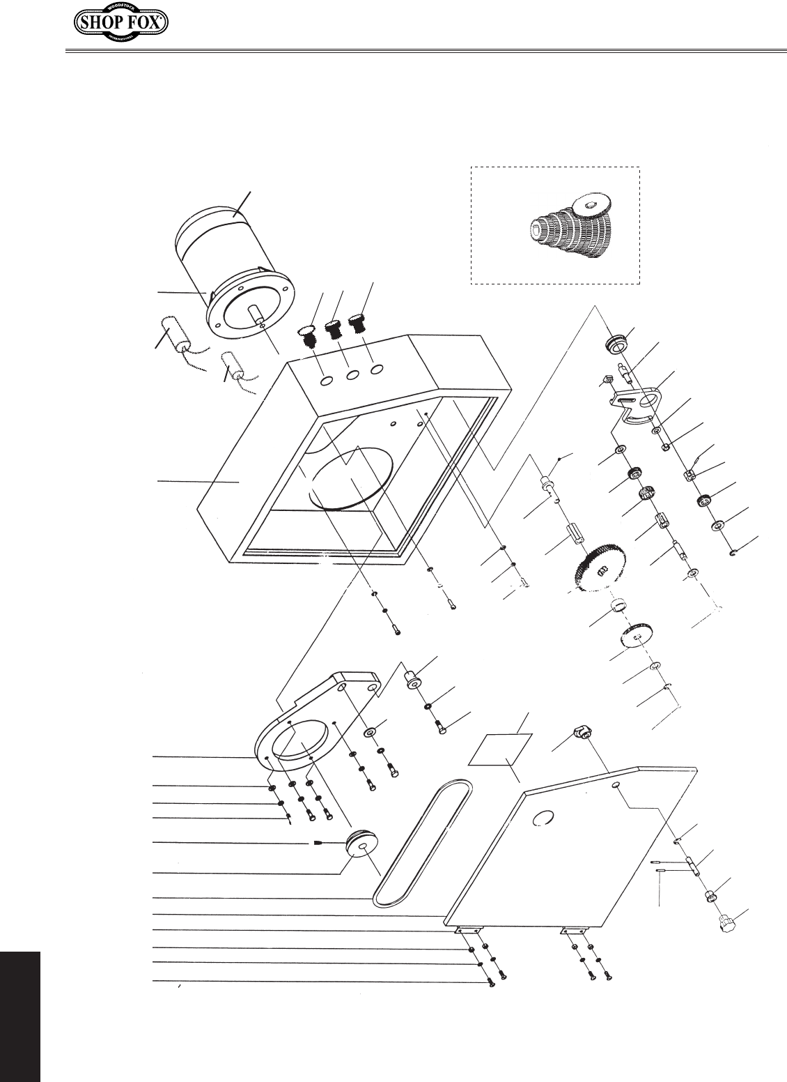
-44-
M1109 Combo Lathe/Mill
PARTS
1 2 3 45678 9 0
111 2
131 4
1
51
61
71
81
91
02
1
2
22
32
42
52
62
72
82
92
03
13
2
3
33
43
53
6
3
73
8
3
9
3
04
14
24
34
44
54
64
7
4
84
94
05
15
25
35
45
4-11
4-2
1
4-3
1
4-4
1
56
57
58
5-1
Change Gears
55-1 to 55-17
Lathe Change Gear Housing Diagram
(0000 Series Parts)

-45-
M1109 Combo Lathe/Mill
PARTS
0000 Series Parts List
REF PART�# DESCRIPTION REF PART�# DESCRIPTION
1 XPS38M PHLP�HD�SCR�M4-.7�X�10 35 XM11090035 EXTENDED�SPLINED�WEAR�BUSHING
2 XPLW02M LOCK�WASHER�4MM 36 XM11090036 CHANGE�GEAR�(60-TOOTH)
3 XPN04M HEX�NUT�M4-.7 37 XM11090037 SPACER�SLEEVE
4 XM11090004 HINGE 38 XM11090038 CHANGE�GEAR�(24-TOOTH)
5 XM11090005 DOOR 39 XPW06M FLAT�WASHER�12MM
5-1 XM11090005-1 CHANGE�GEAR�CHART 40 XM11090040 E-CLIP�12MM
6 XPVA71 V-BELT�A-71�4L710 41 XM11090041 BALL�OILER�6MM
7 XM11090007 PULLEY 42 XPW03M FLAT�WASHER�6MM
8 XPSS03M SET�SCREW�M6-1�X�8 43 XPLW03M LOCK�WASHER�6MM
9 XPB07M HEX�BOLT�M8-1.25�X�25 44 XPSB01M CAP�SCREW�M6-1�X�16
10 XPLW04M LOCK�WASHER�8MM 45 XM11090045 SHOULDER�BUSHING
11 XPW01M FLAT�WASHER�8MM 46 XPLW06M LOCK�WASHER�10MM
12 XM11090012 MOTOR�MOUNT�PLATE 47 XPB116M HEX�BOLT�M10-1.5�X�45
13 XM11090013 COMPOUND�BOX 48 XPW04M FLAT�WASHER�10MM
14 XM11090014 MOTOR�3/4HP�220V 49 XM11090049 DOOR�LATCH
14-1 XM11090014-1 RUN�CAPACITOR�20MFD/450VAC 50 XPEC09M E-CLIP�6MM
14-2 XM11090014-2 S.�CAPACITOR�150MFD/250VAC 51 XM11090051 TUMBLER�SHAFT
14-3 XM11090014-3 MOTOR�FAN 52 XM11090052 SHOULDER�SLEEVE
14-4 XM11090014-4 FAN�COVER 53 XM11090053 STAR-GRIP�KNOB�#8-32
15 XM11090015 SLEEVE 54 XM11090054 TAPER�PINS
16 XM11090016 SHAFT 55-1 XM11090055-1 CHANGE�GEAR�(24-TOOTH)
17 XM11090017 LASH�ADJUSTER 55-2 XM11090055-2 CHANGE�GEAR�(25-TOOTH)
18 XPW04M FLAT�WASHER�10MM 55-3 XM11090055-3 CHANGE�GEAR�(27-TOOTH)
19 XPN02M HEX�NUT�M10-1.5 55-4 XM11090055-4 CHANGE�GEAR�(28-TOOTH)
20 XM11090020 ROLL�PIN�3�X�18MM 55-5 XM11090055-5 CHANGE�GEAR�(30-TOOTH)
21 XM11090021 SPLINED�WEAR�BUSHING�55-6 XM11090055-6 CHANGE�GEAR�(32-TOOTH)
(13MM�LONG) 55-7 XM11090055-7 CHANGE�GEAR�(34-TOOTH)
22 XM11090022 CHANGE�GEAR�(48-TOOTH) 55-8 XM11090055-8 CHANGE�GEAR�(35-TOOTH)
23 XPW06M FLAT�WASHER�12MM 55-9 XM11090055-9 CHANGE�GEAR�(36-TOOTH)
24 XPEC12M E-CLIP�12MM 55-10 XM11090055-10 CHANGE�GEAR�(40-TOOTH)
25 XM11090025 T-NUT 55-11 XM11090055-11 CHANGE�GEAR�(42-TOOTH)
26 XM11090026 SPECIAL�SCREW 55-12 XM11090055-12 CHANGE�GEAR�(44-TOOTH)
27 XPW06M FLAT�WASHER�12MM 55-13 XM11090055-13 CHANGE�GEAR�(46-TOOTH)
28 XM11090028 CHANGE�GEAR�(50-TOOTH) 55-14 XM11090055-14 CHANGE�GEAR�(48-TOOTH)
29 XM11090029 CHANGE�GEAR�(25-TOOTH) 55-15 XM11090055-15 CHANGE�GEAR�(50-TOOTH)
30 XM11090030 SPLINED�WEAR��BUSHING�55-16 XM11090055-16 CHANGE�GEAR�(52-TOOTH)
(26MM�LONG) 55-17 XM11090055-17 CHANGE�GEAR�(60-TOOTH)
31 XM11090031 IDLER�SHAFT 56 XM11090056 EMERGENCY�STOP�SWITCH
32 XPW06M FLAT�WASHER�12MM 57 XM11090057 GREEN�POWER�LAMP
33 XM11090033 E-CLIP�12MM 58 XM11090058 JOG�BUTTON
34 XM11090034 IDLER�SHAFT
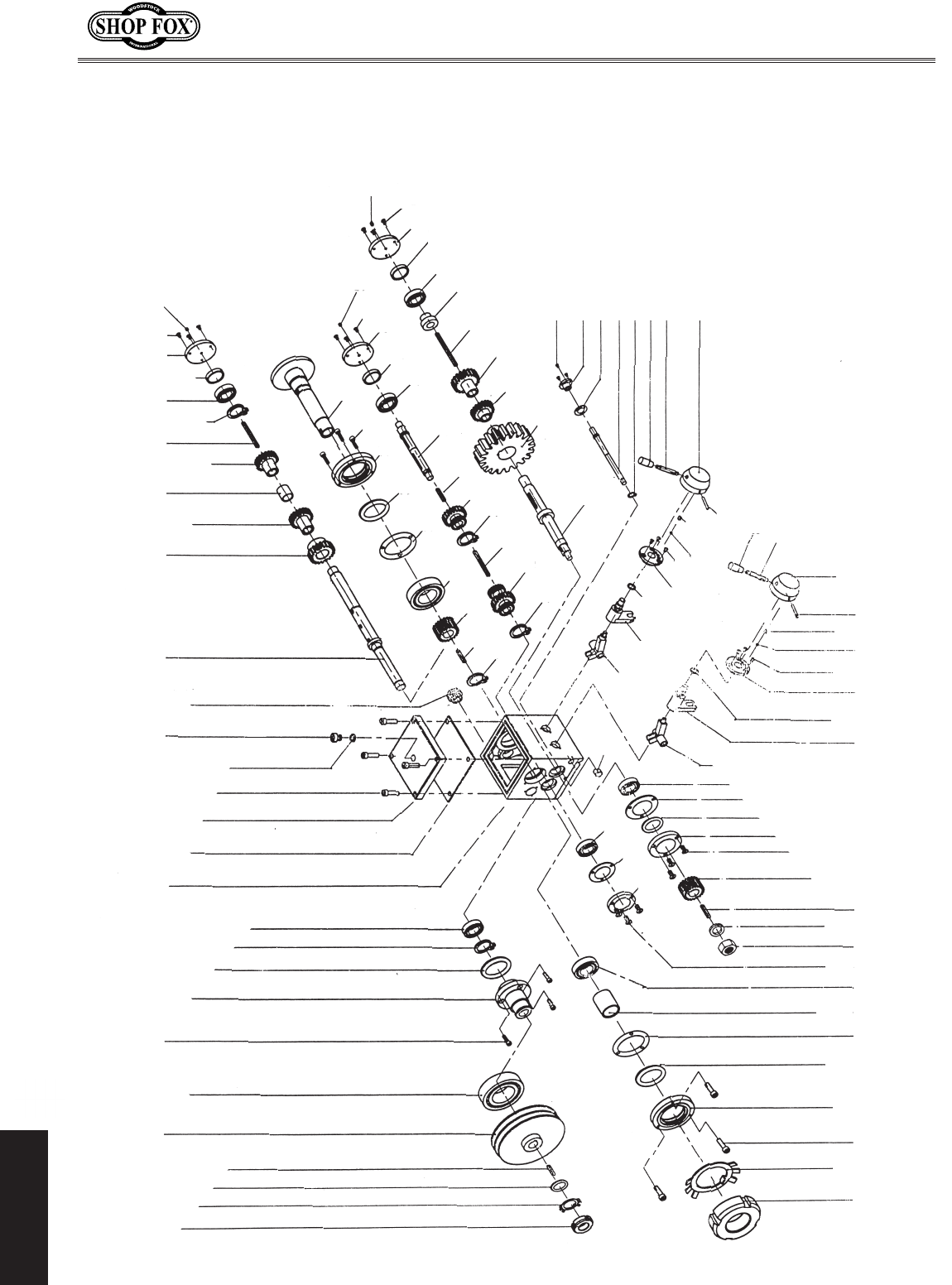
-46-
M1109 Combo Lathe/Mill
PARTS
Thread Dial Diagram
(1000 Series Parts)
1001
1002
1003
1004
1005
1006
1007
1008
1009
101
1
2
101
3
1011014
6
101
7
101
1018
1019 1020
1021
1022
1023
1024
1025
1026
1027
1028
1007
1030
1031
10321033
1034
1035
1036
1037
1038
1039
1040
1041
1042
1043
1044 1045
1046
1047
1048 1049
1007
1051
1052
1053
1054
1055
1056
1057
1058 1059
1060
1062
1007
1064
1065
1066
1067
1068
1069
1070
1071
1072
10731074
10751007
10771078
1079
1080
1081
2
108
3
108
4
108
5
108
1007
7
108
8
108
9
108
3
109
4
109
1007
7
109
8
109
9
109
1007
4
0
11
5
0
11
6
0
11
7
0
11
8
0
11
9
0
11
1110
1111
1100
1101
1102
6
109
6-1
109
0
101
1015
2
109
1
109
0
109
1007

-47-
M1109 Combo Lathe/Mill
PARTS
1000 Series Parts List
REF PART�# DESCRIPTION REF PART�# DESCRIPTION
1001 XM11091001 SPANNER�NUT�M16-1.5 1056 XM11091056 KEY�5�X�5�X�60
1002 XM11091002 TANG�WASHER 1057 XM11091057 SPACER�SLEEVE�
1003 XPW08M FLAT�WASHER�16MM 1058 XM11091011 BALL�BEARING�203
1004 XPK08M KEY�5�X�5�X�16 1059 XM11091059 SLEEVE
1005 XM11091005 SPINDLE�PULLEY 1060 XM11091060 END�CAP
1006 XM11091006 TAPER�ROLLER�BEARING�60206 1062 XPSS03M SET�SCREW�M6-1�X�8
1007 XPSB33M CAP�SCREW�M5-.8�X�12 1064 XM11091064 FIXED�FLANGE
1008 XM11091008 HUB 1065 XM11091065 SPANNER�WASHER�45MM
1009 XM11091009 FELT�SEAL 1066 XM11091066 SHIFT�FORK�SHAFT
1010 XPR06M EXT�RETAINING�RING�16MM 1067 XPR03M EXT�RETAINING�RING�12MM
1011 XM11091011 BALL�BEARING�203 1068 XM11091068 FEMALE�KNOB�M8-1.25�X�40
1012 XM11091012 HEADSTOCK�CASTING 1069 XM11091069 LEVER
1013 XM11091013 GASKET 1070 XM11091070 LEVER�HUB
1014 XM11091014 HEADSTOCK�COVER 1071 XM11091071 OIL�DRAIN
1015 XPSB13M CAP�SCREW�M8-1.25�X�30 1072 XM11091072 RIGHT�SHIFTING�FORK
1016 XM11091016 O-RING�30�X�20�X�2MM 1073 XM11091073 RIGHT�SHIFTING�FORK�SHAFT
1017 XM11091017 FILL�PLUG 1074 XM11091074 O-RING
1018 XM11091018 SIGHT�GLASS 1075 XM11091075 FIXED�FLANGE
1019 XM11091019 SPINDLE�SHAFT 1077 XM11091077 STEEL�BALL�6.5MM
1020 XM11091020 GEAR�(42-TOOTH) 1078 XM11091078 COMPRESSION�SPRING
1021 XM11091021 GEAR�(20-TOOTH) 1079 XM11091079 TAPER�PIN
1022 XM11091022 SLEEVE�SPACER 1080 XM11091080 FEMALE�KNOB�M8-1.25�X�40
1023 XM11091023 GEAR�(30-TOOTH) 1081 XM11091081 LEVER
1024 XPK13M KEY�5�X�5�X�70 1082 XM11091082 LEVER�HUB
1025 XPR07M EXT�RETAINING�RING�18MM 1083 XM11091083 TAPER�PIN
1026 XM11091011 BALL�BEARING�203 1084 XM11091084 COMPRESSION�SPRING
1027 XM11091027 BEARING�SLEEVE 1085 XM11091077 STEEL�BALL�6.5MM
1028 XM11091028 END�CAP 1087 XM11091087 FLANGE
1030 XPSS03M SET�SCREW�M6-1�X�8 1088 XM11091088 OIL�SEAL�16�X�2.4MM
1031 XPR78M EXT�RETAINING�RING�55MM 1089 XM11091089 LEFT�SHIFTING�FORK�SHAFT
1032 XM11091032 THIN�FLAT�KEY 1090 XM11091090 LEFT�SHIFTING�FORK�
1033 XM11091033 GEAR�(56-TOOTH) 1091 XM11091011 BALL�BEARING�203
1034 XM11091034 TAPER�ROLLER�BEARING�D2007112 1092 XM11091092 SPANNER�WASHER
1035 XM11091035 SPANNER�WASHER�120MM 1093 XM11091093 FELT�RING
1036 XM11091036 FELT�RING 1094 XM11091094 FLANGE
1037 XM11091037 MAINSHAFT�OIL�SEAL 1096 XM11091096 KEYED�DRIVE�GEAR�
1038 XPB42M HEX�BOLT�M5-.8�X�20 (24-FINE�TOOTH)
1039 XM11091039 LATHE�SPINDLE 1096-1 XM11091096-1 KEYED�DRIVE�GEAR�SET�
1040 XPR09M EXT�RETAINING�RING�20MM (28�&�35-CORSE�TOOTH)
1041 XM11091041 CLUSTER�GEAR 1097 XPK05M KEY�4�X�4�X�10
1042 XM11091042 KEY�5�X�5�X�60 1098 XPLW06M LOCK�WASHER�10MM
1043 XPR09M EXT�RETAINING�RING�20MM 1099 XPN02M HEX�NUT�M10-1.5
1044 XM11091044 COMBO�GEAR�(22/57-TOOTH) 1100 XM11091011 BALL�BEARING�203
1045 XPK02M KEY�5�X�5�X�40 1101 XM11091101 SPANNER�WASHER�60MM
1046 XM11091046 INTERMEDIATE�SHAFT 1102 XM11091102 END�CAP
1047 XM11091011 BALL�BEARING�203 1104 XM11091104 TAPER�ROLLER�BEARING�2007110
1048 XM11091048 SLEEVE 1105 XM11091105 SPECIAL�WASHER
1049 XM11091049 END�CAP 1106 XM11091106 SPANNER�WASHER�105MM
1051 XPSS03M SET�SCREW�M6-1�X�8 1107 XM11091107 FELT�RING
1052 XM11091052 OUTPUT�SHAFT 1108 XM11091108 END�CAP
1053 XM11091053 HUGE�GEAR�(68-TOOTH) 1109 XM11091109 CAP�SCREW
1054 XM11091054 GEAR�(33-TOOTH) 1110 XM11091110 TANG�WASHER
1055 XM11091055 GEAR�(56-TOOTH) 1111 XM11091111 SPANNER�NUT
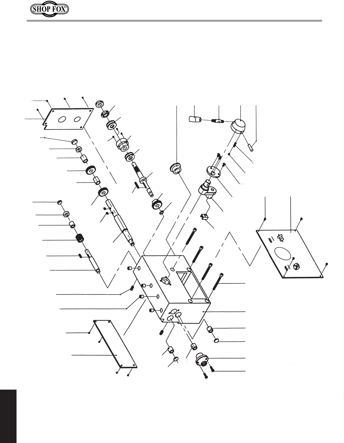
-48-
M1109 Combo Lathe/Mill
PARTS
2001
2002
2003 2004
2005
2006 2007 2008 2009 2010
2014
2015
2016
2017
2018
2019
2011
2012
2013
2023
2027
2021
2022
2024
2025
2026
2028
2029
2030
2031
2032
2033
2034
2035
2036
2037
2038
2039
2040
2041
2042
2048 2047 2046 2045 2044 2043
2049
2050
2051
2020
Leadscrew Gearbox Diagram
(2000 Series Parts)

-49-
M1109 Combo Lathe/Mill
PARTS
2000 Series Parts List
REF PART�# DESCRIPTION REF PART�# DESCRIPTION
2001 XM11092001 COVER�PLATE 2027 XPSB24M CAP�SCREW�M5-.8�X�16
2002 XPS05M PHLP�HD�SCR�M5-.8�X�8 2028 XP8102 BEARING�8102
2003 XM11092003 BALL�OILER�8MM 2029 XM11092029 SPANNER�NUT
2004 XM11092004 SPECIAL�SET�SCREW�M5-.8�X�6 2030 XM11092030 FLANGE�HUB
2005 XM11092005 SHAFT 2031 XM11092031 FEMALE�KNOB�M8-1.25�X�40MM
2006 XPK08M KEY�5�X�5�X�16 2032 XM11092032 LEVER
2007 XM11092007 GEAR�(20-TOOTH) 2033 XM11092033 LEVER�HUB
2008 XM11092008 SPACER 2034 XM11092034 TAPER�PIN
2009 XM11092009 SLEEVE 2035 XM11092035 SHIFTING�YOKE
2010 XM11092010 PLUG 2036 XM11092036 SHIFTING�FORK
2011 XM11092011 SHAFT�2037 XM11092037 LOCATING�PLATE
2012 XPK127M KEY�5�X�5�X�8 2038 XPFH07M FLAT�HD�SCR�M5-.8�X�10
2013 XM11092013 GEAR�(20-TOOTH) 2039 XM11091077 STEEL�BALL�6.5MM
2014 XM11092014 SPACER 2040 XM11092040 COMPRESSION�SPRING
2015 XM11092015 GEAR�(20-TOOTH) 2041 XPS12M PHLP�HD�SCR�M3-.5�X�6
2016 XM11092016 SPACER 2042 XM11092042 FRONT�PANEL
2017 XM11092017 SLEEVE 2043 XM11092043 CAP�SCREW�M8-1.25�X�100
2018 XM11092018 PLUG 2044 XM11092044 HOUSING
2019 XM11092019 COVER�PLATE 2045 XM11092045 BUSHING
2020 XPS07M PHLP�HD�SCR�M4-.7�X�8 2046 XM11092046 PLUG
2021 XPR06M EXT�RETAINING�RING�16MM 2047 XM11092047 FLANGE�HUB
2022 XM11092022 GEAR�(20-TOOTH) 2048 XPSB33M CAP�SCREW�M5-.8�X�12
2023 XPK126M KEY�5�X�5�X�32 2049 XM11092049 BUSHING
2024 XM11092024 SHAFT 2050 XM11092050 PLUG
2025 XP51102 BEARING��8102 2051 XM11092051 BUSHING
2026 XM11092026 FLANGE�HUB
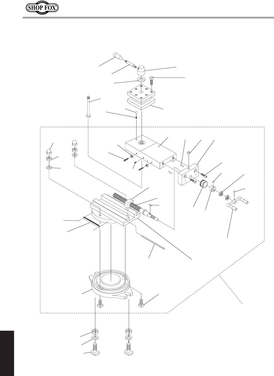
-50-
M1109 Combo Lathe/Mill
PARTS
Compound Rest and Tool Post Diagram
(2500 Series Parts)

-51-
M1109 Combo Lathe/Mill
PARTS
2500 Series Parts List
REF PART�# DESCRIPTION REF PART�# DESCRIPTION
2501 XM11092501 FEMALE�KNOB�5/16-18 2521 XM11092521 SPANNER�NUT
2502 XM11092502 LEVER�5/16-20 2522 XM11092522 TAPERED�PIN
2503 XM11092503 TOOL�POST�BOLT�M10-1.5�X�20 2523 XM11092523 HANDLE�ASSY
2504 XM11092504 LEVER�HUB 2524 XM11092524 LEAD�SCREW
2505 XM11092505 SPACER 2525 XM11092525 LEAD�SCREW�NUT
2506 XM11092506 FOUR-WAY�TOOL�POST 2526 XM11092526 SPECIAL�KEY
2507 XM11092507 SLIDE 2527 XM11092527 WAY�BASE
2508 XM11092508 DETENT�PIN 2528 XM11092528 GIB
2509 XM11092509 COMPRESSION�SPRING 2529 XM11092529 SCALE�PLATE
2510 XPSS64M SET�SCREW�M6-1�X�15 2530 XM11092530 RIVET
2511 XPN01M HEX�NUT�M6-1 2531 XPN18M ACORN�NUT�M8-1.25
2512 XPSS01M SET�SCREW�M6-1�X�10 2532 XPN03M HEX�NUT�M8-1.25
2513 XM11092513 T-BOLT 2533 XPW01M FLAT�WASHER�8MM
2514 XM11092514 DOWEL�PIN 2534 XM11092534 BASE
2515 XM11092515 BALL�OILER 2535 XM11092535 T-NUT�M8-1.25�X�25
2516 XPSB01M CAP�SCREW�M6-1�X�16 2536 XM11092536 T-NUT�M10-1.5�X�32
2517 XM11092517 END�BLOCK 2537 XPW04M FLAT�WASHER�10MM
2518 XM11092518 SCALE�HUB 2538 XPN02M HEX�NUT�M10-1.5
2519 XM11092519 FLAT�SPRING 2539 XM11092539 COMPLETE�COMPOUND�REST
2520 XM11092520 HUB
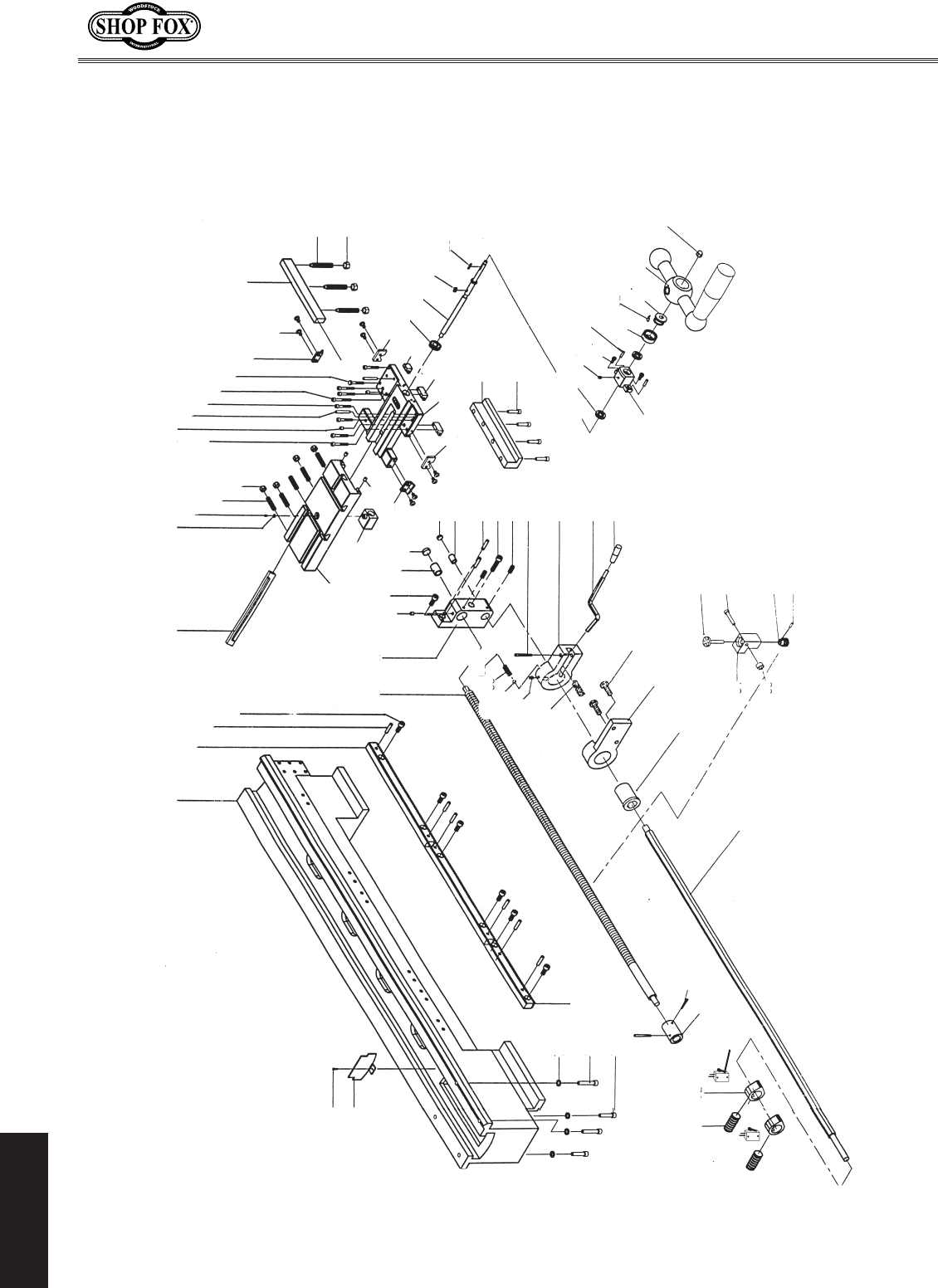
-52-
M1109 Combo Lathe/Mill
PARTS
Bed Diagram
(3000 Series Parts)
3079
3078
3075
3076
3077
3073 3072
3071
3070
3064
3074
3063
3061
3084
3085
3083
3082
3081
3080
3069
3068
3067
3046 3047 3049
30503051
3052
3053
3054
3055
3056
3057
3058
3059
3060
3036
3028 3030
3032
3033 3034
3035
3038
0373
3023
3024
3025
3026
3041
3040
3039
3022
3021
3044
3045
3042
3043
3019
3020
3001 3005 3006
3007
3008
3009
3013
3014
3015
3016
3017
3018
3072-1
3002
3003
3004
3012
3011
3010
3048
3062
3065
3066
3027
3031
3029

-53-
M1109 Combo Lathe/Mill
PARTS
3000 Series Parts List
REF PART�# DESCRIPTION REF PART�# DESCRIPTION
3001 XM11093001 BED 3044 XM11093044 CROSS�NUT
3002 XM11093002 RACK�SET 3045 XM11093045 WORKTABLE
3003 XM11093003 TAPER�PIN 3046 XM11093046 LONGITUDINAL�FEED�SCREW
3004 XPSB11M CAP�SCREW�M8-1.25�X�16 3047 XM11093047 LEADSCREW�ENDCAP
3005 XM11093005 CHOCK 3048 XM11093028 BALL�OILER�6MM
3006 XM11093006 SPECIAL�FLAT�WASHER 3049 XPSB14M CAP�SCREW�M8-1.25�X�20
3007 XPS08M PHLP�HD�SCR�M5-.8�X�12 3050 XM11093050 SLEEVE
3008 XPSS12M SET�SCREW�SCR�M6-1�X�25 3051 XM11093051 PLUG
3009 XPN01M HEX�NUT�M6-1 3052 XM11093052 PLUG
3010 XPSB48M CAP�SCREW�M6-1�X�35 3053 XM11093053 BUSHING
3011 XM11093011 BALL�OILER�8MM 3054 XM11093054 TAPER�PIN
3012 XM11093012 TAPER�PIN 3055 XPSB35M CAP�SCREW�M8-1.25�X�60
3013 XPSB07M CAP�SCREW�M6-1�X�30 3056 XM11093056 SPECIAL�SET�SCREW�M5-.8�X�10
3014 XPSB30M CAP�SCREW�M6-1�X�45 3057 XPRP91M ROLL�PIN�5�X�35
3015 XPB47M HEX�BOLT�M6-1�X�40 3058 XM11093058 LOCKING�HANDLE�SEAT
3016 XM11093016 WIPER 3059 XM11093059 LEVER
3017 XPFH07M FLAT�HD�SCR�M5-.8�X�10 3060 XM11093060 FEMALE�KNOB�M10-1.5�X�32
3018 XM11093018 CHOCK 3061 XPSB26M CAP�SCREW�M6-1�X�12
3019 XPSS09M SET�SCREW�M8-1.25�X�20 3062 XM11093062 PEDESTAL
3020 XPN03M HEX�NUT�M8-1.25 3063 XM11093063 SLEEVE
3021 XM11093021 WIPER 3064 XM11093064 CONTROL�ROD
3022 XM11093022 BLOCK 3065 XM11093065 SPECIAL�SET�SCREW�M8-1.25�X�8
3023 XM11093023 GEAR�(20-TOOTH) 3066 XM11093066 COMPRESSION�SPRING�
3024 XM11093024 CROSS�FEED�LEAD�SCREW 3067 XM11093028 STEEL�BALL�6MM
3025 XPK08M KEY�5�X�5�X�16 3068 XM11093068 SPECIAL�SET�SCREW�M8-1.25�X�15
3026 XPK29M KEY�4�X�4�X�8 3069 XM11093069 COMPRESSION�SPRING�
3027 XP8201 BALL�BEARING�8201 3070 XM11093070 TAPER�PIN
3028 XM11093028 STEEL�BALL�6MM 3071 XM11093071 COUPLING�SLEEVE
3029 XPB83M HEX�BOLT�M6-1�X�16 3072 XM11093072 CAM�LOBE
3030 XM11093030 TAPER�PIN�5�X�20MM 3072-1 XM11093072-1 LIMIT�SWITCH
3031 XM11093031 DIAL 3073 XM11093073 SPECIAL�SET�SCREW�M4-.7�X�6
3032 XM11093032 FLAT�SPRING 3074 XM11093074 RACK�SET
3033 XM11093033 DIAL�SLEEVE 3075 XPW04M FLAT�WASHER�10MM
3034 XM11093034 CRANK�HANDLE 3076 XPSB47M CAP�SCREW�M10-1.5�X�40
3035 XPN41M ACORN�NUT�M10-1.5 3077 XPSB84M CAP�SCREW�M10-1.5�X�35
3036 XM11093036 LEAD�SCREW�NUT�HOUSING 3078 XM11093078 SHIELD
3037 XPSB12M CAP�SCREW�M8-1.25�X�40 3079 XPSB50M CAP�SCREW�M5-.8�X�10
3038 XM11093038 L-BLOCK�LONG 3080 XM11093080 TAPER�PIN
3039 XM11093039 L-BLOCK�SMALL 3081 XM11093081 WORM�WHEEL
3040 XM11093040 CARRIAGE�3082 XPSB29M CAP�SCREW�M6-1�X�40
3041 XM11093041 WIPER 3083 XM11093083 THREAD�INDICATOR
3042 XM11093042 WIPER 3084 XM11093084 THREAD�DIAL�HOUSING
3043 XM11093028 BALL�OILER�6MM 3085 XPN01M HEX�NUT�M6-1
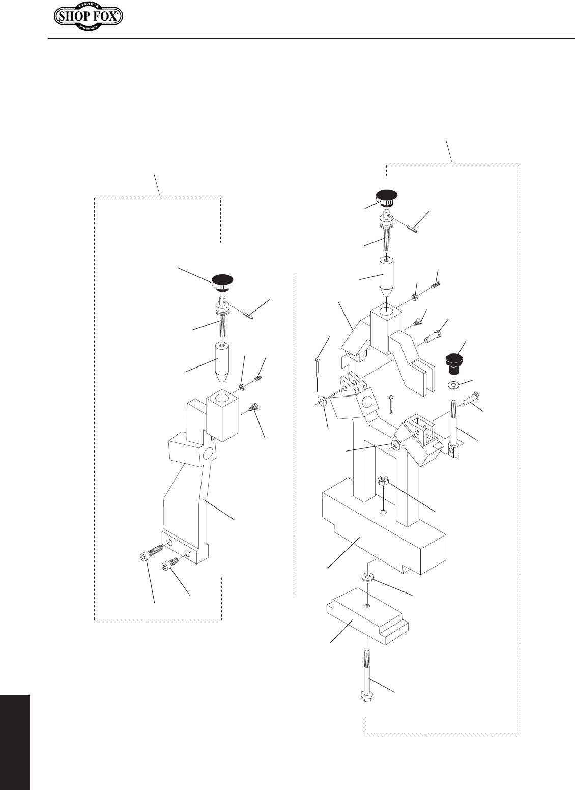
-54-
M1109 Combo Lathe/Mill
PARTS
Steady Rest and Follow Rest Diagram
(3500 Series Parts)

-55-
M1109 Combo Lathe/Mill
PARTS
3500 Series Parts List
REF PART�# DESCRIPTION REF PART�# DESCRIPTION
3501 XM11093501 PINNED�KNOB 3514 XM11093514 SPECIAL�EYE�BOLT
3502 XM11093502 ADJUSTMENT�STUD 3515 XPW04M FLAT�WASHER�10MM
3503 XM11093503 TAPERED�PIN 3516 XPN02M HEX�NUT�M10-1.5
3504 XM11093504 BRASS-TIPPED�FINGER 3517 XM11093517 CHOCK
3505 XM11093505 SPECIAL�SET�SCREW�M6-1 3518 XPB120M HEX�BOLT�M10-1.5�X�65
3506 XPN01M HEX�NUT�M6-1 3519 XPSB14M CAP�SCREW�M8-1.25�X�20
3507 XM11093507 THUMB�KNOB�M6-1.0�X�20 3520 XPSB31M CAP�SCREW�M8-1.25�X�25
3508 XM11093508 CLEVIS�PIN�8�X�32MM 3521 XM11093521 FOLLOW�REST�CASTING
3509 XM11093509 COTTER�PIN�3�X�25MM 3522 XM11093522 COMPLETE�FOLLOW�REST
3510 XM11093510 STEADY�REST�HEAD 3523 XM11093523 COMPLETE�STEADY�REST
3511 XPW01M FLAT�WASHER�8MM 3524 XPW03M FLAT�WASHER�6MM
3512 XM11093512 STEADY�REST�BASE 3525 XM11093525 CLEVIS�PIN�6�X�32MM
3513 XM11093513 FEMALE�KNOB�M8-1.25
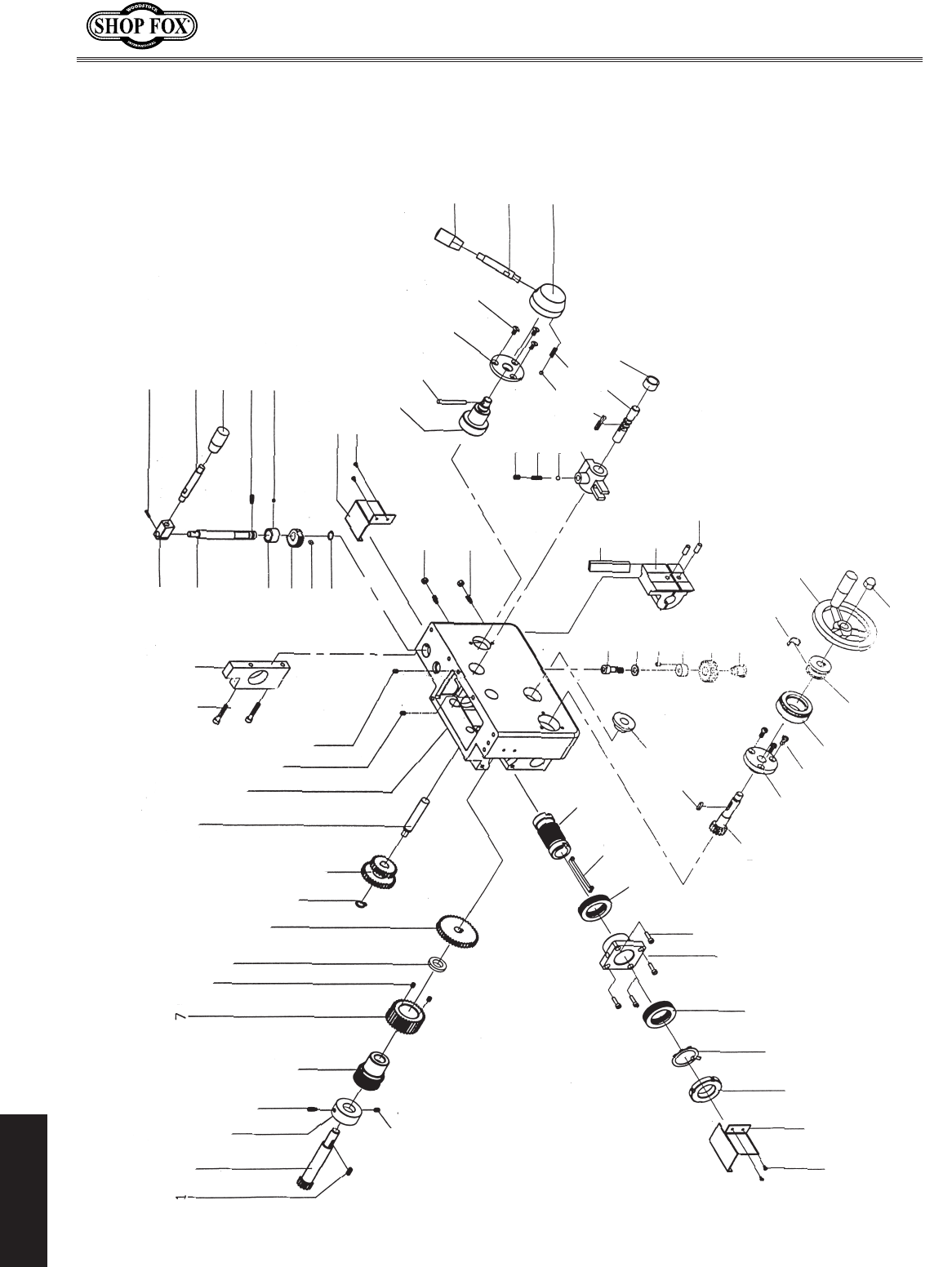
-56-
M1109 Combo Lathe/Mill
PARTS
Apron Diagram
(4000 Series Parts)
4001 4002
4003
4004
4005
4006
4007
4008
4009
4010
4011
4012
4013
4014
4015
4016
4017 4018
4019
4020
4021
4022
4023
40244025
4026
4027
4028
4029
4030
4031
4032
4033
4034
4035
4036
4037
4038
4039
4040
4041
4042
4043
4044
4045
4047
4048
4049
4050
4051
4052
4053
4054
4055
4056
4057
4058
4059
4060
4061
4062
4063
4064
4065
4066
4067
4068
4069
4070
4071
4073
4074
4075
4076
4077
4078
4046
4072
4079

-57-
M1109 Combo Lathe/Mill
PARTS
4000 Series Parts List
REF PART�# DESCRIPTION REF PART�# DESCRIPTION
4001 XPK81M KEY�6�X�6�X�12 4041 XM11094041 COMPRESSION�SPRING
4002 XM11094002 GEAR�SHAFT 4042 XM11094042 STEEL�BALL�6.5MM
4003 XM11094003 LOCK�COLLAR 4043 XM11094043 SPECIAL�SET�SCREW�M6-1.0�X�8
4004 XM11094004 SET�SCREW�M6-1.0�X�12 4044 XM11094044 COMPRESSION�SPRING
4005 XM11094005 SPECIAL�SET�SCREW�M6-1.0�X�12 4045 XM11094045 STEEL�BALL�5MM
4006 XM11094006 WORM�GEAR 4046 XM11094046 SHIFTING�FORK
4007 XM11094007 GEAR�(40-TOOTH) 4047 XPK02M KEY�5�X�5�X�40
4008 XM11094008 SPECIAL�SET�SCREW�M5-.8�X�8 4048 XM11094048 SHIFTING�FORK�SHAFT
4009 XM11094009 SPACER 4049 XM11094049 SLEEVE
4010 XM11094010 GEAR�(60-TOOTH) 4050 XM11094050 GIB
4011 XPR09M EXT�RETAINING�RING�20MM 4051 XM11094051 HALF�NUT�SET
4012 XM11094012 CLUSTER�GEAR 4052 XM11094052 ALIGNMENT�PINS�6�X�8MM
4013 XM11094013 SHAFT 4053 XPSB06M CAP�SCREW�M6-1�X�25
4014 XM11094014 CASE 4054 XPLW03M LOCK�WASHER�6MM
4015 XM11094015 SPECIAL�SET�SCREW�M5-.8�X�16 4055 XM11094055 SPECIAL�SET�SCREW�M4-.7�X�8
4016 XM11094016 SPECIAL�SET�SCREW�M6-1.0�X�20 4056 XM11094056 SLEEVE
4017 XPSB79M CAP�SCREW�M5-.8�X�35 4057 XM11094057 MIDDLE�GEAR
4018 XM11094018 APRON�END�BLOCK 4058 XM11094058 STUB�HUB
4019 XPR03M EXT�RETAINING�RING�12MM 4059 XM11094059 BEARING�SLEEVE
4020 XPK29M KEY�4�X�4�X�8 4060 XPK125M KEY�4�X�4�X�28
4021 XM11094021 GEAR�(30-TOOTH) 4061 XM11094061 FLAT�SPRING
4022 XM11094022 SPACER 4062 XM11094062 HAND�WHEEL
4023 XM11094023 SHAFT 4063 XPN42M ACORN�NUT�M12�X�1.5
4024 XM11094024 ANGLE�BLOCK 4064 XM11094064 SLEEVE
4025 XM11094025 TAPER�PIN 4065 XM11094065 DIAL
4026 XM11094026 LEVER 4066 XPS02M PHLP�HD�SCR�M4-.7�X�12
4027 XM11094027 FEMALE�KNOB�M8-1.25�X�40MM 4067 XM11094067 FLANGE�SLEEVE
4028 XPSS34M SET�SCREW�M5-.8�X�16 4068 XM11094068 GEAR�SHAFT
4029 XM11094029 SPECIAL�SET�SCREW�M5-.8�X�8 4069 XM11094069 WORM�SHAFT
4030 XM11094030 COVER 4070 XM11094070 SADDLE�KEY�4�X�28
4031 XPS05M PHLP�HD�SCR�M5-.8�X�8 4071 XP8106 THRUST�BEARING�8106
4032 XPN06M HEX�NUT�M5-.8 4072 XPSB24M CAP�SCREW�M5-.8�X�16
4033 XM11094033 SPECIAL�SET�SCREW�M5-.8�X�25 4073 XM11094073 FIXED�FLANGE�HUB
4034 XM11094034 STUB�HUB 4074 XP8106 THRUST�BEARING�8106
4035 XM11094035 TAPER�PIN 4075 XM11094075 TANG�WASHER
4036 XM11094036 FLANGE�HUB 4076 XM11094076 SPANNER�NUT�M30-1.5
4037 XPFH25M FLAT�HD�SCR�M4-.7�X�12 4077 XM11094077 PLATE
4038 XM11094038 FEMALE�KNOB�M8-1.25�X�40MM 4078 XPS05M PHLP�HD�SCR�M5-.8�X�8
4039 XM11094039 LEVER 4079 XM11094079 HOUSING
4040 XM11094040 LEVER�HUB
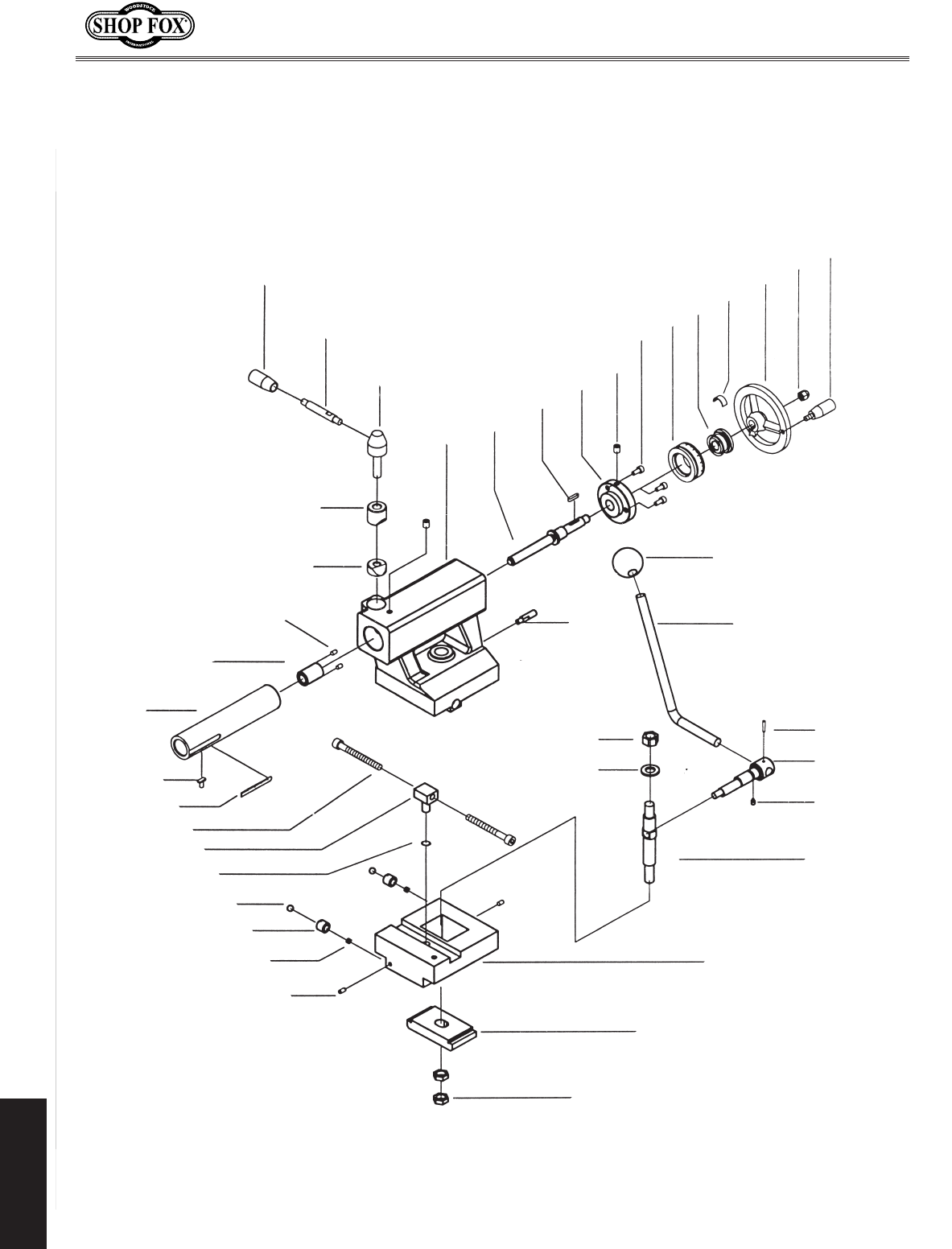
-58-
M1109 Combo Lathe/Mill
PARTS
Tailstock Diagram
(5000 Series Parts)
5015
5016
5017
5018 5019
5020
5021
5022
5023
5024
5025
5026
5027
5028 5029
5030
5031
5032
5033
5034
5035
5036
5037
5038
5040
5041
5039
5014
5013
5012
5011
5010
5009
5008
5007
5006
5005
5004
5003
5002
5001

-59-
M1109 Combo Lathe/Mill
PARTS
REF PART�# DESCRIPTION REF PART�# DESCRIPTION
5001 XM11095001 SPECIAL�SET�SCREW�M5-.8�X�8 5022 XM11093028 BALL�OILER�6MM
5002 XM11095002 COMPRESSION�SPRING 5023 XPSB33M CAP�SCREW�M5-.8�X�12
5003 XM11095003 BALL�OILER 5024 XM11095024 DIAL
5004 XM11095004 STEEL�BALL�8MM 5025 XM11095025 SLEEVE
5005 XPR03M EXT�RETAINING�RING�12MM 5026 XM11095026 FLAT�SPRING
5006 XM11095006 DOWEL�NUT 5027 XM11095027 HAND�WHEEL
5007 XPSB12M CAP�SCREW�M8-1.25�X�40 5028 XPN41M ACORN�NUT�M10-1.5
5008 XM11095008 SCALE�LABEL 5029 XM11095029 HANDLE
5009 XM11095009 T-KEY 5030 XM11095030 FEMALE�KNOB�M10-1.5�X�32
5010 XM11095010 BARREL 5031 XM11095031 LEVER
5011 XM11095011 COLLAR�SLEEVE 5032 XM11095032 TAPER�PINS
5012 XM11095012 SPECIAL�SET�SCREW�M5-.8�X�10 5033 XM11095033 SHAFT
5013 XM11095013 WEDGE�NUT 5034 XM11095034 SPECIAL�SET�SCREW�M5-.8�X�12
5014 XM11095014 WEDGE�SLEEVE 5035 XM11095035 PULL�SHAFT
5015 XM11095015 FEMALE�KNOB�M8-1.25�X�40MM 5036 XM11095036 BASE
5016 XM11095016 LEVER 5037 XM11095037 CHOCK
5017 XM11095017 LEVER�HUB 5038 XM11095038 SPECIAL�HEX�NUT�M12-1.5
5018 XM11095018 TAILSTOCK�HOUSING 5039 XM11095039 PIN
5019 XM11095019 TAILSTOCK�STEM 5040 XM11095040 SPECIAL�HEX�NUT�M12-1.75
5020 XPK125M KEY�4�X�4�X�28 5041 XPW06M FLAT�WASHER�12MM
5021 XM11095021 FLANGE�HUB
5000 Series Parts List
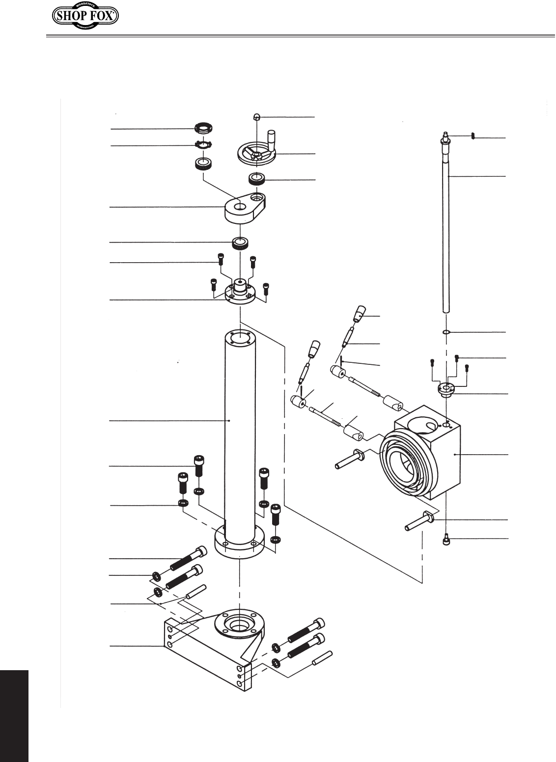
-60-
M1109 Combo Lathe/Mill
PARTS
Mill Column Diagram
(6000 Series Parts)
6013
6012
6011
6010
6009
6008
6007
6006
6005
6004
6003
6002
6001
6027
6026
6025
6028
6029
6030
6014
6015
6016
6017
6018
6019
6020
6021
6022
6023
6024

-61-
M1109 Combo Lathe/Mill
PARTS
REF PART�# DESCRIPTION REF PART�# DESCRIPTION
6001 XM11096001 PEDESTAL 6016 XP8103 BALL�BEARING�8103
6002 XM11096002 TAPER�PIN 6017 XPK69M KEY�4�X�4�X�12
6003 XPLW05M LOCK�WASHER�12MM 6018 XM11096018 HEADSTOCK�LEAD�SCREW
6004 XPSB92M CAP�SCREW�M12-1.75�X�40 6019 XPR18M EXT�RETAINING�RING�17MM
6005 XPLW05M LOCK�WASHER�12MM 6020 XPSB06M CAP�SCREW�M6-1�X�25
6006 XPSB119M CAP�SCREW�M12-1.75�X�55 6021 XM11096021 LEADSCREW�NUT
6007 XM11096007 COLUMN 6022 XM11096022 COLUMN�BRACKET
6008 XM11096008 COLUMN�FLANGE 6023 XM11096023 T-BOLT
6009 XPSB02M CAP�SCREW�M6-1�X�20 6024 XM11096024 SPECIAL�SHOULDER�SCREW
6010 XP8106 BALL�BEARING�8106 6025 XM11096025 WEDGE�SLEEVE
6011 XM11096011 COLUMN�BRACKET 6026 XM11096026 LOCK�STUD
6012 XM11096012 TANG�WASHER 6027 XM11096027 LEVER�HUB
6013 XM11096013 SPANNER�NUT�M30-1.5 6028 XM11096028 TAPER�PIN
6014 XPN41M ACORN�NUT�M10-1.5 6029 XM11096029 LEVER
6015 XM11096015 HAND�WHEEL 6030 XM11096030 FEMALE�KNOB�M8-1.25�X�40
6000 Series Parts List
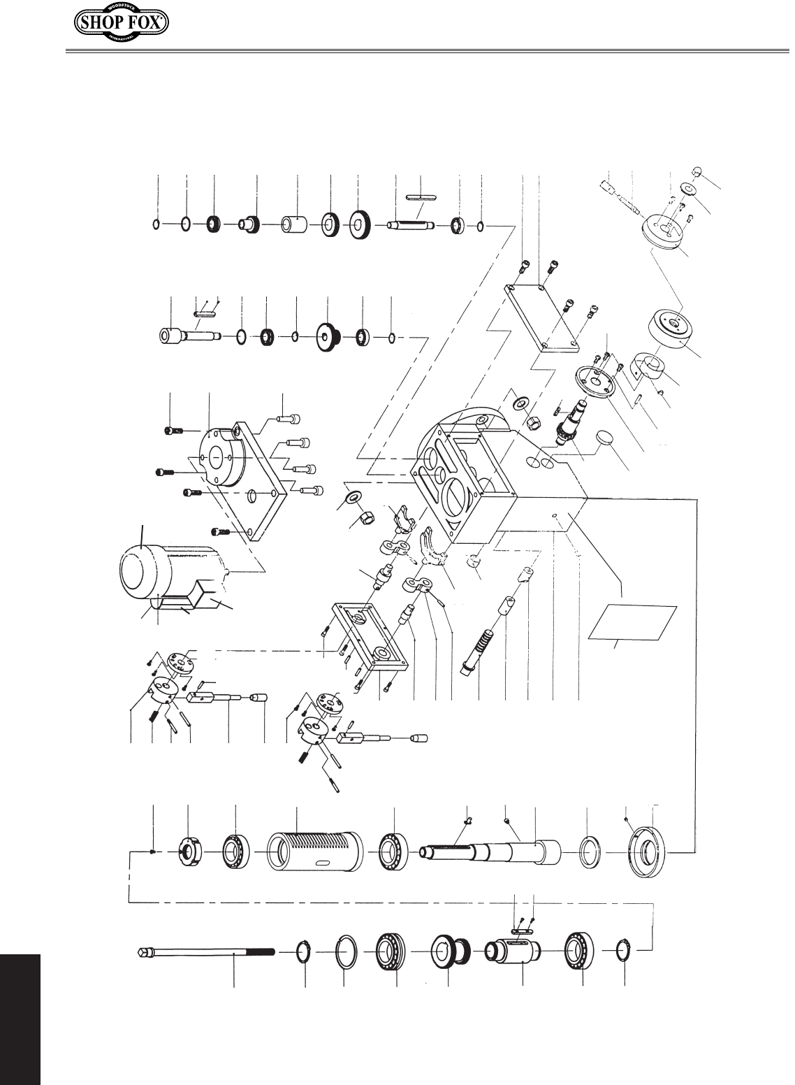
-62-
M1109 Combo Lathe/Mill
PARTS
7001
7002
7003
7004
7005
7006
7007
7008
7009
7010
7011
7012
7013
7014
7015
7016
7017
7018
7088
7019
7020
7021
7022
7023
7024
7025
7026
7027
7028
7032
7033
7034
7035 7036
7037
7038
7039
7040
7041
7042
7043
7044
7045
7046
7047
7048
7049
7050
7051
7052
7053
7054
7055
7056
7057
7058
7059
7060
7061
7062
7063
7064
7065
7066
7067
7068
7069
7070
7071
7072
7073
7074
7075
7076
7077
7078
7079
7080
7081
7082
7083
7084
7085
7086
7087
7030
7031
7029
7043-4
7043-5
7043-2
7043-3
7089
7043-1
Headstock Diagram
(7000 Series Parts)

-63-
M1109 Combo Lathe/Mill
PARTS
7000 Series Parts List
REF PART�# DESCRIPTION REF PART�# DESCRIPTION
7001 XPR12M EXT�RETAINING�RING�35MM 7043-5 XM11097043-5 POWER�SWITCH�BOX
7002 XM11097002 ROLLER�BEARING�207 7044 XPW04M FLAT�WASHER�10MM
7003 XM11097003 SHAFT�SLEEVE 7045 XPN02M HEX�NUT�M10-1.5
7004 XM11097004 CLUSTER�GEAR 7046 XM11097046 SHIFTING�FORK�SHAFT
7005 XM11097005 BALL�BEARING�50207 7047 XM11097047 SMALL�SHIFTING�FORK
7006 XM11097006 BEARING�LOOP 7048 XPSB14M CAP�SCREW�M8-1.25�X�20
7007 XPR12M EXT�RETAINING�RING�35MM 7049 XM11097049 MOTOR�MOUNT�PLATE
7008 XM11097008 DRAW�BAR�7/16-20 7050 XPSB02M CAP�SCREW�M6-1�X�20
7009 XM11097009 SPECIAL�KEY�7051 XM11097051 INPUT�SHAFT
7010 XM11097010 SPECIAL�SET�SCREW�M3-.5�X�8 7052 XPK112M KEY�5�X�5�X�50
7011 XPFH31M FLAT�HD�SCR�M4-.7�X�8 7053 XM11097053 SPECIAL�SCREW
7012 XM11097012 SPANNER�NUT�M30-1.5 7054 XM11097054 BEARING�LOOP
7013 XM11097013 TAPER�ROLLER�BEARING�2007106 7055 XP50207 BALL�BEARING�50207
7014 XM11097014 RACK 7056 XPR18M EXT�RETAINING�RING�17MM
7015 XM11097015 TAPER�ROLLER�BEARING�D2007107 7057 XM11097057 CLUSTER�GEAR
7016 XM11097016 T-KEY 7058 XP60201 BALL�BEARING�60201
7017 XM11097017 SPINDLE�(R8) 7059 XPR03M EXT�RETAINING�RING�12MM
7018 XM11097018 FELT�SEAT 7060 XPR03M EXT�RETAINING�RING�12MM
7019 XM11097019 SPECIAL�SET�SCREW�M4-.7�X�12 7061 XM11097061 BEARING�LOOP
7020 XM11097020 BEARING�CAP 7062 XP50207 BALL�BEARING�50207
7021 XM11097021 LEVER�HUB 7063 XM11097063 GEAR�(21-TOOTH)
7022 XM11097022 COMPRESSION�SPRING 7064 XM11097064 SPACER
7023 XM11097023 PIVOT�STUD 7065 XM11097065 GEAR�(39-TOOTH)
7024 XM11097024 TAPER�PIN 7066 XM11097066 GEAR�(45-TOOTH)
7025 XM11097025 LEVER 7067 XM11097067 IDLER�SHAFT
7026 XM11097026 FEMALE�KNOB�M8-1.25�X�40MM 7068 XPK112M KEY�5�X�5�X�55
7027 XPSB18M CAP�SCREW�M4-.7�X�8 7069 XP60201 BALL�BEARING�60201
7028 XM11097028 STRAIGHT�PIN 7070 XPR03M EXT�RETAINING�RING�12MM
7029 XM11097029 LOCATING�PLATE 7071 XPSB24M CAP�SCREW�M5-.8�X�16
7030 XPSB24M CAP�SCREW�M5-.8�X�16 7072 XM11097072 GEARBOX�COVER
7031 XM11097031 TAPER�PIN 7073 XM11097073 FEMALE�KNOB�M8-1.25�X�40
7032 XM11097032 SHIFTER�COVER 7074 XM11097074 LEVER
7033 XM11097033 SHIFTING�FORK�SHAFT 7075 XPFH41M FLAT�HD�SCR�M4-.7�X�16
7034 XM11097034 ROCKER�ARM 7076 XPN18M ACORN�NUT�M8-1.25
7035 XM11097035 TAPER�PIN 7077 XM11097077 ADJUSTMENT�WASHER
7036 XM11097036 LARGE�SHIFT�FORK 7078 XM11097078 LEVER�HUB
7037 XM11097037 END�SLEEVE 7079 XM11097079 CALIBRATED�DIAL
7038 XM11097038 LOCK�STUD 7080 XM11097080 COILED�FLAT�SPRING
7039 XM11097039 SLEEVE�NUT 7081 XPS07M PHLP�HD�SCR�M4-.7�X�8
7040 XM11097040 WEDGE�NUT 7082 XM11097082 PIN
7041 XM11097041 GEARBOX�CASE 7083 XM11097083 FLANGE�HUB
7042 XPSB76M CAP�SCREW�M8-1.25�X�18 7084 XM11097084 CAP
7043 XM11097043 MOTOR�220V�3/4�HP 7085 XM11097085 PINION�GEAR�SHAFT
7043-1 XM11097043-1 CAPACITOR�200UF/250VAC 7086 XPK06M KEY�5�X�5�X�10
7043-2 XM11097043-2 FAN�COVER 7087 XPB96M HEX�BOLT�M5-.8�X�10
7043-3 XM11097043-3 FAN 7088 XM11097088 SPECIAL�SHOULDER�SCREW
7043-4 XM11097043-4 POWER�SWITCH�7089 XM11097089 CONVERSION�DATA�PLATE
(KJD12,�230VAC,�5E4)�
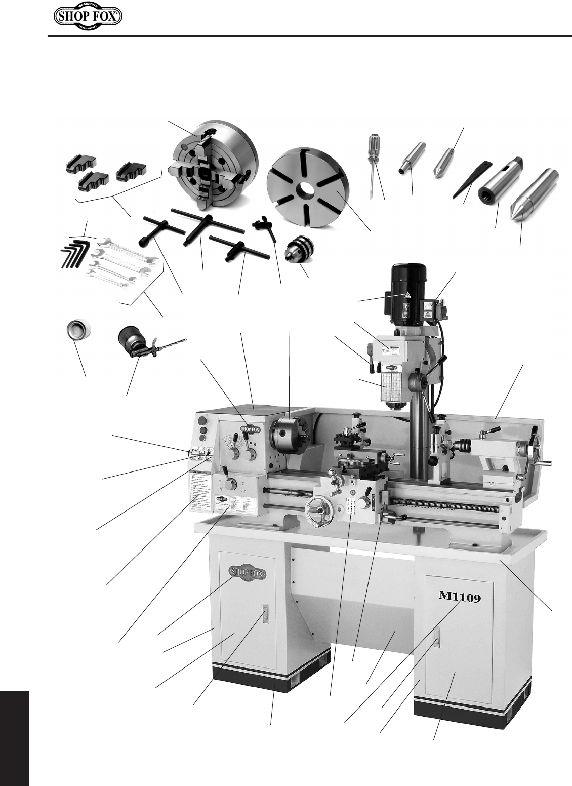
-64-
M1109 Combo Lathe/Mill
PARTS
Accessories and Labels Diagram
(8000 Series Parts)
8021
8040
8039
8048
8047
8046
8001
8042
8022
8013
8004
8005
8011
8017
8007
8009
8033
8015
8008
8041
8045
8044
8006
8010
8023
8012
8018
8014
8016
8020
8026
8025
8043
8036
8028
8030
8032
8034
8037
8038
8029
8031
8027
8035
8024

-65-
M1109 Combo Lathe/Mill
PARTS
8000 Series Parts List
REF PART�# DESCRIPTION REF PART�# DESCRIPTION
8001 XM11098001 6"�THREE-JAW�CHUCK 8022 XM11098022 DRILL�CHUCK�KEY
8004 XM11098004 8"�FOUR-JAW�UNIVERSAL�CHUCK 8023 XM11098023 BACK�SPLASH
8005 XM11098005 8"�FACEPLATE 8024 XM11098024 CHIP�TRAY
8006 XM11098006 FOUR-JAW�CHUCK�KEY 8025 XM11098025 THREAD�DIAL
8007 XM11098007 DRILL�CHUCK�(1-13MM,�JT-33) 8026 XM11098026 KICK�PANEL
8008 XM11098008 WRENCH�SET�8027 XM11098027 COMPLETE�RT�DOOR�LATCH�ASSY
(8/10,�10/12,�14/17,�17/19�MM) 8028 XM11098028 COMPLETE�LFT�DOOR�LATCH�ASSY
8008-1 XM11098008-1 COMBINATION�WRENCH�8/10 8029 XM11098029 RT�DOOR�W/HINDGES�AND�LOCK
8008-2 XM11098008-2 COMBINATION�WRENCH�10/12 8030 XM11098030 LFT�DOOR�W/HINDGES�AND�LOCK
8008-3 XM11098008-3 COMBINATION�WRENCH�14/17 8031 XM11098031 COMPLETE�RT�CABINET�W/DOOR
8008-4 XM11098008-4 COMBINATION�WRENCH�17/19 8032 XM11098032 COMPLETE�LFT�CABINET�W/DOOR
8009 XM11098009 HEX�WRENCH�SET�(2,�4,�6,�8,�MM) 8033 XM11098033 RUBBER�MAT
8009-1 XPAW02M HEX�WRENCH�4MM 8034 XM11098034 SHOP�FOX�LOGO�PLATE
8009-2 XPAW04M HEX�WRENCH�4MM 8035 XM11098035 M1109�LABEL
8009-3 XPAW06M HEX�WRENCH�6MM 8036 XM11098036 BLACK�TRIM�TAPE
8009-4 XPAW08M HEX�WRENCH�8MM 8037 XM11098037 DATA�LABEL
8010 XM11098010 THREE-JAW�CHUCK�KEY 8038 XM11098038 GENERAL�WARNING�LABEL
8011 XM11098011 OIL�CAN 8039 XM11098039 WEAR�EYEPROTECTION�LABEL
8012 XM11098012 DEAD�CENTER�MT#5 8040 XM11098040 READ�MANUAL�FIRST�LABEL
8013 XM11098013 STANDARD�SCREWDRIVER�#2�8041 XM11098041 TIE�BACK�LOOSE�CLOTHING�LABEL
8014 XM11098014 WEDGE 8042 XM11098042 SHOP�FOX�DOMED�LOGO�LABEL
8015 XM11098015 TOOL�POST�T-HANDLE�WRENCH 8043 XM11098043 THREAD�DIAL�CHART�LABEL
8016 XM11098016 DEAD�CENTER�MT#3 8044 XM11098044 INCH/METRIC�CONVERSION�CHART
8017 XM11098017 THREE-JAW�CHUCK�INT.�JAWS 8045 XM11098045 MILL�GEAR�BOX�SPEED�LABEL
8018 XM11098018 TAPER�ADAPTER�MT#3�TO�MT#5 8046 XM11098046 WEAR�EYEPROTECTION�LABEL
8020 XM11098020 ARBOR�JT-33�TO�MT#3 8047 XM11098047 ELECTRICAL�HAZARD�LABEL
8021 XM11098021 SPOT�PAINT 8048 XM11098048 READ�MANUAL�FIRST�LABEL
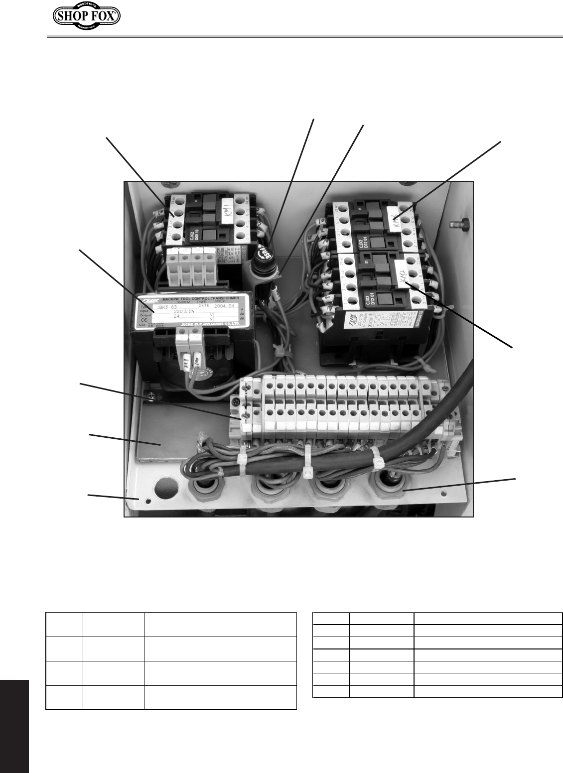
-66-
M1109 Combo Lathe/Mill
PARTS
Main Wiring Box Diagram
(9000 Series Parts)
9003
9009
9002
9007
9006
9001
9004
9008
9011
9010
9000 Series Parts List
REF PART�# DESCRIPTION REF PART�# DESCRIPTION
9001 XM11099001 CONTACTOR�9006 XM11099006 FUSE�2A
(LC1-D0910,�B5,�24V,�50HZ)�9007 XM11099007 FUSE�HOUSING
9002 XM11099002 CONTACTOR�9008 XM11099008 TERMINAL�BLOCK
(LC1-D1201,�B5,�24V,�50HZ)�9009 XM11099009 STRAIN�RELIEF
9003 XM11099003 CONTACTOR�9010 XM11099010 ELECTRICAL�BOX
(LC1-D1201,�B5,�24V,�50HZ)�9010-1 XM11099010-1 ELECTRICAL�BOX�COVER
9004 XM11099004 TRANSFORMER��(JBK5-63),�9011 XM11099011 CONTACTOR�MOUNTING�PLATE
(INPUT�220V�+/-�5%,�OUTPUT�24V)

-67-
M1109 Combo Lathe/Mill
PARTS
Notes

-68-
M1109 Combo Lathe/Mill
PARTS
Warranty
Woodstock International, Inc. warrants all SHOP FOX® machinery to be free of defects from work-
manship and materials for a period of two years from the date of original purchase by the original
owner. This warranty does not apply to defects due directly or indirectly to misuse, abuse, negligence
or accidents, lack of maintenance, or reimbursement of third party expenses incurred.
Woodstock International, Inc. will repair or replace, at its expense and at its option, the SHOP FOX®
machine or machine part which in normal use has proven to be defective, provided that the original
owner returns the product prepaid to the SHOP FOX® factory service center or authorized repair
facility designated by our Bellingham, WA office, with proof of their purchase of the product within
two years, and provides Woodstock International, Inc. reasonable opportunity to verify the alleged
defect through inspection. If it is determined there is no defect, or that the defect resulted from
causes not within the scope of Woodstock International Inc.'s warranty, then the original owner must
bear the cost of storing and returning the product.
This is Woodstock International, Inc.'s sole written warranty and any and all warranties that may be
implied by law, including any merchantability or fitness, for any particular purpose, are hereby limited
to the duration of this written warranty. We do not warrant that SHOP FOX® machinery complies
with the provisions of any law or acts. In no event shall Woodstock International, Inc.'s liability under
this warranty exceed the purchase price paid for the product, and any legal actions brought against
Woodstock International, Inc. shall be tried in the State of Washington, County of Whatcom. We shall
in no event be liable for death, injuries to persons or property or for incidental, contingent, special or
consequential damages arising from the use of our products.
Every effort has been made to ensure that all SHOP FOX® machinery meets high quality and durabil-
ity standards. We reserve the right to change specifications at any time because of our commitment to
continuously improve the quality of our products.

CUT ALONG DOTTED LINE
Name ___________________________________________________________________________________
Street __________________________________________________________________________________
City _________________________ State ___________________________Zip ________________________
Phone # ______________________ Email __________________________Invoice # ___________________
Model #_________Serial #______________Dealer Name__________________Purchase Date___________
Warranty Registration
The following information is given on a voluntary basis. It will be used for marketing purposes to help us
develop better products and services. Of course, all information is strictly confidential.
1. How did you learn about us?
_____ Advertisement ____ Friend ____ Local Store
_____ Mail Order Catalog ____ Website ____ Other:
2. How long have you been a woodworker/metalworker?
_____ 0-2 Years _____ 2-8 Years ____ 8-20 Years _____ 20+ Years
3. How many of your machines or tools are Shop Fox®?
_____ 0-2 _____ 3-5 ____ 6-9 _____ 10+
4. Do you think your machine represents a good value? _____ Yes ____ No
5. Would you recommend Shop Fox® products to a friend? _____ Yes ____ No
6. What is your age group?
_____ 20-29 ____ 30-39 ____ 40-49
_____ 50-59 ____ 60-69 ____ 70+
7. What is your annual household income?
_____ $20,000-$29,000 ____ $30,000-$39,000 ____ $40,000-$49,000
_____ $50,000-$59,000 ____ $60,000-$69,000 ____ $70,000+
8. Which of the following magazines do you subscribe to?
9. Comments: __________________________________________________________________
_____________________________________________________________________________
_____________________________________________________________________________
_____________________________________________________________________________
____ Cabinet Maker
____ Family Handyman
____ Hand Loader
____ Handy
____ Home Shop Machinist
____ Journal of Light Cont.
____ Live Steam
____ Model Airplane News
____ Modeltec
____ Old House Journal
____ Popular Mechanics
____ Popular Science
____ Popular Woodworking
____ Practical Homeowner
____ Precision Shooter
____ Projects in Metal
____ RC Modeler
____ Rifle
____ Shop Notes
____ Shotgun News
____ Today’s Homeowner
____ Wood
____ Wooden Boat
____ Woodshop News
____ Woodsmith
____ Woodwork
____ Woodworker West
____ Woodworker’s Journal
____ Other:

TAPE ALONG EDGES--PLEASE DO NOT STAPLE
FOLD ALONG DOTTED LINE
FOLD ALONG DOTTED LINE
WOODSTOCK INTERNATIONAL INC.
P.O. BOX 2309
BELLINGHAM, WA 98227-2309
Place
Stamp
Here
