Woodstock W1811 Users Manual 11.17.08
W1811 to the manual fb7cdaa1-9534-43d7-ad48-b6d404b453d1
2015-02-03
: Woodstock Woodstock-W1811-Users-Manual-478226 woodstock-w1811-users-manual-478226 woodstock pdf
Open the PDF directly: View PDF ![]() .
.
Page Count: 84

DLC:GHB6CJ6A
BD9:AL&-&&
&%HA>9>C<I67A:H6L
E]dcZ/(+%,()"()-'Dca^cZIZX]c^XVaHjeedgi/iZX]"hjeedgi5h]de[dm#W^o
8DENG><=ICDK:B7:G!'%%-7NLDD9HID8@>CI:GC6I>DC6A!>C8#
L6GC>C</CDEDGI>DCD;I=>HB6CJ6AB6N7:G:EGD9J8:9>C6CNH=6E:DG;DGBL>I=DJI
I=:LG>II:C6EEGDK6AD;LDD9HID8@>CI:GC6I>DC6A!>C8# Eg^ciZY^cIV^lVc
&&&*(IG

K_`jdXelXcgifm`[\jZi`k`ZXcjX]\kp`ejkilZk`fejfek_\gifg\ij\klg#
fg\iXk`fe#dX`ek\eXeZ\Xe[j\im`Z\f]k_`jdXZ_`e\&\hl`gd\ek%
=X`cli\kfi\X[#le[\ijkXe[Xe[]fccfnk_\`ejkilZk`fej^`m\e`ek_`j
dXelXcdXpi\jlck`ej\i`fljg\ijfeXc`ealip#`eZcl[`e^XdglkXk`fe#
\c\ZkifZlk`fefi[\Xk_%
K_\fne\if]k_`jdXZ_`e\&\hl`gd\ek`jjfc\cpi\jgfej`Yc\]fi`kjjX]\
lj\%K_`ji\jgfej`Y`c`kp`eZcl[\jYlk`jefkc`d`k\[kfgifg\i`ejkXccX$
k`fe`eXjX]\\em`ifed\ek#g\ijfee\ckiX`e`e^Xe[ljX^\Xlk_fi`qX$
k`fe#gifg\i`ejg\Zk`feXe[dX`ek\eXeZ\#dXelXcXmX`cXY`c`kpXe[
Zfdgi\_\ej`fe#Xggc`ZXk`fef]jX]\kp[\m`Z\j#YcX[\&Zlkk\i`ek\^i`kp#
Xe[k_\ljX^\f]g\ijfeXcgifk\Zk`m\\hl`gd\ek%
K_\dXel]XZkli\in`ccefkY\_\c[c`XYc\]fi`ealipfigifg\ikp
[XdX^\]ifde\^c`^\eZ\#`dgifg\ikiX`e`e^#dXZ_`e\df[`]`ZXk`fejfi
d`jlj\%
Jfd\[ljkZi\Xk\[Ypgfn\ijXe[`e^#jXn`e^#^i`e[`e^#[i`cc`e^#Xe[
fk_\iZfejkilZk`feXZk`m`k`\jZfekX`ejZ_\d`ZXcjbefnekfk_\JkXk\f]
:Xc`]fie`XkfZXlj\ZXeZ\i#Y`ik_[\]\Zkjfifk_\ii\gif[lZk`m\_Xid%
Jfd\\oXdgc\jf]k_\j\Z_\d`ZXcjXi\1
C\X[]ifdc\X[$YXj\[gX`ekj%
:ipjkXcc`e\j`c`ZX]ifdYi`Zbj#Z\d\ekXe[fk_\idXjfeipgif[lZkj%
8ij\e`ZXe[Z_ifd`ld]ifdZ_\d`ZXccp$ki\Xk\[cldY\i%
Pflii`jb]ifdk_\j\\ogfjli\jmXi`\j#[\g\e[`e^fe_fnf]k\epfl
[fk_`jkpg\f]nfib%Kfi\[lZ\pfli\ogfjli\kfk_\j\Z_\d`ZXcj1
Nfib`eXn\ccm\ek`cXk\[Xi\X#Xe[nfibn`k_Xggifm\[jX]\kp\hl`g$
d\ek#jlZ_Xjk_fj\[ljkdXjbjk_XkXi\jg\Z`Xccp[\j`^e\[kf]`ck\i
flkd`ZifjZfg`ZgXik`Zc\j%

J<KLG<C<:KI@:8C D8@EK<E8E:< J<IM@:< G8IKJFG<I8K@FEJJ8=<KP@EKIF;L:K@FE
LJ<K?<HL@:B>L@;<G8><C89<CJKFJ<8I:?FLK@E=FID8K@FE=8JK
@EKIF;L:K@FE%%%%%%%%%%%%%%%%%%%%%%%%%%%%%%%%%%%%%)
Woodstock Technical Support .................. 2
Overview of Machine ............................ 2
Controls and Features ........................... 3
Machine Specifications .......................... 4
Sliding Table Saw Capacities ................... 6
J8=<KP%%%%%%%%%%%%%%%%%%%%%%%%%%%%%%%%%%%%%%%%%%%%%%%.
Standard Machinery Safety ..................... 7
Additional Safety for Sliding Table Saws ..... 9
Preventing Kickback ........................... 10
Protecting Yourself From Kickback .......... 10
Glossary Of Terms .............................. 11
<C<:KI@:8C%%%%%%%%%%%%%%%%%%%%%%%%%%%%%%%%%%%%%%% ()
220V Single-Phase Operation ................. 12
Extension Cords ................................ 12
Electrical Specifications ...................... 12
J<KLG%%%%%%%%%%%%%%%%%%%%%%%%%%%%%%%%%%%%%%%%%%%%%% (*
Items Needed for Setup ....................... 13
Unpacking ....................................... 13
Inventory ........................................ 14
Machine Placement ............................ 16
Cleaning Machine ............................... 16
Lifting & Moving ................................ 17
Assembly & Setup .............................. 18
Dust Collection ................................. 27
Power Connection .............................. 28
Test Run .......................................... 28
FG<I8K@FEJ%%%%%%%%%%%%%%%%%%%%%%%%%%%%%%%%%%%%%%% *'
General .......................................... 30
Safety Habits .................................... 30
Workpiece Inspection .......................... 31
Non-Through & Through Cuts ................ 32
Main Blade Installation ........................ 33
Blade Guard ..................................... 34
Riving Knife ..................................... 35
Riving Knife Adjustment....................... 36
Scoring Blade Installation & Adjustment ... 37
Dado Blade Installation ....................... 38
Rip Cutting ...................................... 40
Crosscutting ..................................... 42
Miter Cutting .................................... 44
Dado Cutting .................................... 45
Rabbet Cutting ................................. 47
Resaw Cutting................................... 49
Shop-Made Safety Accessories................ 51
D8@EK<E8E:<%%%%%%%%%%%%%%%%%%%%%%%%%%%%%%%%%%%% ,)
Schedule ......................................... 52
Cleaning ......................................... 52
Table & Base .................................... 52
Lubrication ...................................... 53
J<IM@:<%%%%%%%%%%%%%%%%%%%%%%%%%%%%%%%%%%%%%%%%%%%% ,+
General .......................................... 54
Belt Service ..................................... 54
Blade Tilt Calibration .......................... 55
Sliding Table Parallelism ...................... 56
Sliding Table Adjustment ...................... 57
Calibrating Crosscut Fence 90° Stops ....... 58
Electrical Safety Instructions ................. 59
Wiring Diagram ................................. 60
Electrical Pictures .............................. 61
Troubleshooting ................................. 62
G8IKJ%%%%%%%%%%%%%%%%%%%%%%%%%%%%%%%%%%%%%%%%%%%%%% -+
Labels & Cosmetics ............................ 64
Cabinet .......................................... 65
Trunnion ......................................... 66
Main Motor ...................................... 67
Tables ............................................ 71
Rip Fence ........................................ 72
Handwheels ..................................... 73
Scoring Trunnion ................................ 74
Crosscut Table .................................. 75
Swing Arm ....................................... 76
Miter Gauge ..................................... 77
Crosscut Fence ................................. 78
N8II8EKP%%%%%%%%%%%%%%%%%%%%%%%%%%%%%%%%%%%%%%%% /(
:fek\ekj

-2-
N(/((('Jc`[`e^KXYc\JXn
@EKIF;L:K@FE
Nff[jkfZbK\Z_e`ZXcJlggfik
Fm\im`\nf]DXZ_`e\
This machine has been specially designed to provide many years of trouble-free service. Close attention
to detail, ruggedly built parts and a rigid quality control program assure safe and reliable operation.
Woodstock International, Inc. is committed to customer satisfaction. Our intent with this manual is to
include the basic information for safety, setup, operation, maintenance, and service of this product.
We stand behind our machines! In the event that questions arise about your machine, please contact
Woodstock International Technical Support at (360) 734-3482 or send e-mail to: k\Z_$jlggfik7j_fg]fo%
Y`q. Our knowledgeable staff will help you troubleshoot problems and process warranty claims.
@EKIF;L:K@FE
If you need the latest edition of this manual, you can download it from _kkg1&&nnn%j_fg]fo%Y`q.
If you have comments about this manual, please contact us at:
Nff[jkfZb@ek\ieXk`feXc#@eZ%
8kke1K\Z_e`ZXc;fZld\ekXk`feDXeX^\i
G%F%9fo)*'0
9\cc`e^_Xd#N80/)).
<dX`c1dXelXcj7nff[jkfZb`ek%Zfd
A sliding table saw is primarily used to rip and crosscut sheet stock or panels in a production setting.
The sliding table makes it much easier and safer to feed these large workpieces through a cut. This saw
can also be used as a traditional table saw for most types of through-cuts.
The primary components of a sliding table saw are the sliding table, the fixed table, the crosscut table
and fence, the rip fence, the main blade and the scoring blade.
A typical cut using the sliding table is made by placing the workpiece on the sliding table and crosscut
table, positioning it against the crosscut fence where needed so the waste portion of the workpiece is on
the opposite side of the blade, and pushing the workpiece through the blade by sliding the table.
The scoring blade may or may not be used, depending on if the workpiece is faced with laminate,
melamine, or other solid surface material, or if tear-out free cuts are required. If the scoring blade
is not needed for cutting operations, it can be lowered under the table so it will stay sharp for later
operations.
When using the sliding table saw as a traditional table saw, the sliding table is locked in place and the
rip fence is then used to guide the workpiece through the cut.
In order to produce accurate results, the sliding table must move parallel to the blade and the scoring
blade must be aligned with the main blade. Similarly, the rip fence must be parallel with the main blade
and the crosscut fence must calibrated to the main blade.
-3-
N(/((('Jc`[`e^KXYc\JXn
@EKIF;L:K@FE
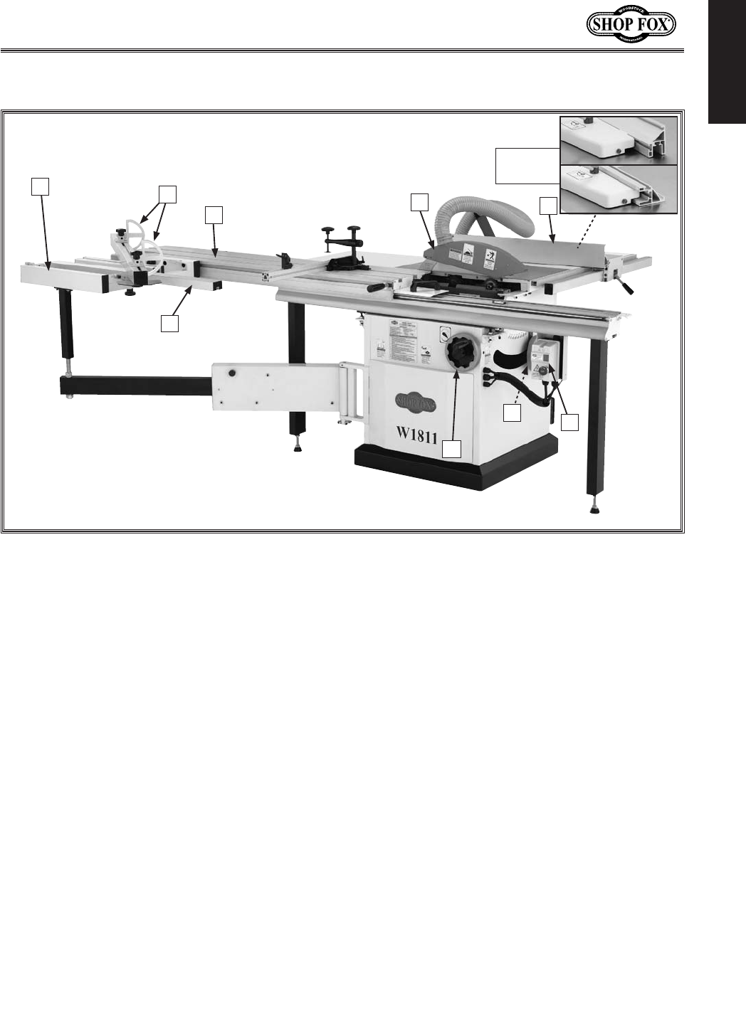
:fekifcjXe[=\Xkli\j
=`^li\(% Main view of machine features and controls.
C
G
H
8% :ifjjZlkKXYc\: Provides a wide, stable
platform for supporting full-size panels
during crosscutting operations. Also fea-
tures an angle scale for cutting miters with
the crosscut fence.
9% =c`gJkfgj: Used for quick measurements
when crosscutting.
:% :ifjjZlk=\eZ\: Used during crosscutting
operations. Features a scale and multiple
flip-style stop blocks (a.k.a. "flip stops")
for precise, repeatable crosscutting opera-
tions. Can also be set up for miter cuts.
;% Jc`[`e^KXYc\: Conveniently glides the
workpiece through the blade with effort-
less precision and ease.
<% 9cX[\>lXi[: Fully-adjustable blade guard
maintains maximum protection around the
saw blade and a 2½" dust port effectively
extracts dust from the cutting operation.
=% I`g=\eZ\: Fence face can be positioned
for standard cutting operations, or in the
lower position for blade guard clearance
during narrow ripping operations.
>% FE&F==Jn`kZ_: Starts and stops main
blade and scoring blade motors. Features
an OFF switch that must be reset between
starting and stopping machine.
?% 9cX[\8e^c\?Xe[n_\\c: Adjusts the angle
of the saw blades.
@% 9cX[\<c\mXk`fe?Xe[n_\\c: Located on
the right-hand side of the cabinet, this
handwheel adjusts the height of the main
saw blade.
A
DE
BF
I
Fence
Positions

-4-
N(/((('Jc`[`e^KXYc\JXn
@EKIF;L:K@FE
Phone #: (360) 734-3482 • Online Tech Support: tech-support@shopfox.biz • Web: www.shopfox.biz
B68=>C:
HE:8>;>86I>DCH
Dfkfi
Type ..........................................................................................TEFC Capacitor Start Induction
Horsepower ................................................................................................................. 5 HP
Voltage ...................................................................................................................... 220V
Phase ....................................................................................................................... Single
Amps .......................................................................................................................... 22A
Speed .................................................................................................................. 3450 RPM
Cycle ........................................................................................................................ 60 Hz
Number Of Speeds ............................................................................................................. 1
Power Transfer .................................................................................................... V-Belt Drive
Bearings ............................................................................................... Sealed and Lubricated
DX`eJg\Z`]`ZXk`fej
:XgXZ`k`\j
Main Blade Arbor Diameter ..........................................................................................5⁄8"
Main Blade Arbor Speed ...................................................................................... 4000 RPM
Main Blade Diameter ................................................................................................. 10"
Maximum Depth Of Cut At 90° .................................................................................... 3
1⁄8"
Maximum Depth Of Cut At 45° .................................................................................... 2
1⁄4"
Blade Tilt ...........................................................................................................0°–45°
Maximum Ripping Width With Standard Rip Fence .............................................................. 33"
Maximum Cross Cutting Width With Crosscut Fence .........................................................78
1⁄2"
Maximum Cross Cutting Length With Crosscut Fence ........................................................... 63"
Scoring Blade Arbor Diameter ................................................................................... 22mm
Scoring Blade Arbor Speed ................................................................................... 8000 RPM
Scoring Blade Diameter ............................................................................................ 3
1⁄8"
Maximum Dado Width .............................................................................................. 13⁄16"
Fm\iXcc;`d\ej`fej
Weight .................................................................................................................. 533 lbs.
Length ......................................................................................................................... 76"
Width ..................................................................................................................... 1243/4"
Height ......................................................................................................................... 46"
Foot Print with Legs (Width/Depth) ............................................................................... 60" x 28"
Cabinet Footprint (Width/Depth) ...............................................................................25
1⁄2" x 28"
Table Size without Extension Wings (Length/Width) .........................................................27" x 14
3⁄8"
Table Size with Extension Wings (Length/Width) ................................................................ 47" x 40"
Sliding Table Size (Length/Width) ............................................................................... 63" x 12
1⁄4"
Crosscut Fence Size (Length/Width)............................................................................781/2" x 1/2"
:fejkilZk`feDXk\i`Xcj
Sliding Table ..........................................................................................................Aluminum
Machine Frame .............................................................................................................Steel
Fences .......................................................................... Extruded Aluminum Side, Aluminum Body
Rails ............................................................................................................. Hardened Steel
Trunnions ............................................................................................................... Cast Iron
Arbor Bearings ........................................................................Sealed And Lubricated Ball Bearings
BD9:AL&-&&&%HA>9>C<I67A:H6L
DXZ_`e\Jg\Z`]`ZXk`fej

-5-
N(/((('Jc`[`e^KXYc\JXn
@EKIF;L:K@FE
J_`gg`e^;`d\ej`fej
Number of Crates .............................................................................................................. 2
Type ........................................................................................................... Cardboard/Wood
Content ..................................................................................................................Machine
Crate 1 Length/Width/Height ............................................................................... 46" x 42" x 44"
Crate 1 Weight ......................................................................................................... 528 lbs.
Crate 2 Length/Width/Height ............................................................................ 67" x 18
1⁄2" x 10"
Crate 2 Weight ......................................................................................................... 117 lbs.
<c\Zki`ZXc
Switch Type ................................................................. Magnetic With Thermal Overload Protection
Switch Voltage .............................................................................................................220V
Cord Provided .................................................................................................................No
Recommended Cord ............................................................................. 10 gauge, 3 Wire, 300VAC
Recommended Circuit Size ................................................................................................ 30A
Plug Provided ..................................................................................................................No
Recommended Plug Type ................................................................................................ L6-30
Fk_\i
Number of Dust Ports ......................................................................................................... 2
Dust Port Size ............................................................................ 2
1⁄2" with Blade Guard, 4" Main"
Customer Assembly Time ........................................................................Approximately 1
1/2 Hours
Warranty .................................................................................................................. 2 Year
Country of Origin ....................................................................................................... Taiwan
=\Xkli\j
Blade Guard With 2
1⁄2" Dust Port
4" Main Dust Port
Adjustable Scoring Knife Kerf
Adjustable Riving Knife
Single Lever Locking Fence
-6-
N(/((('Jc`[`e^KXYc\JXn
@EKIF;L:K@FE
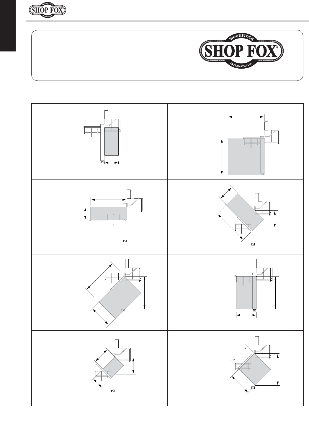
Ripping Width
Miter Cut 90º
(push cut)
Miter Cut 45º
Miter Cut 45º
(push cut)
Cross Cut
(fence not extended)
Miter Cut 45º
(push cut, fence not extended)
Miter Cut 45º
(fence not extended)
Cross Cut
Phone #: (360) 734-3482 • Online Tech Support: tech-support@shopfox.biz • Web: www.shopfox.biz
HA>9>C<I67A:
H6L86E68>I>:H
BD9:AL&-&&&%HA>9>C<I67A:H6L
**
./$(&)
-*
,'
-/
+/
+/$*&+
-*
./$*&+
++
$
*($(&)
+/$*&+
++$(&)
*($(&)
./$*&+
-*
+/
./$*&+
*.
Jc`[`e^KXYc\JXn:XgXZ`k`\j

-7-
N(/((('Jc`[`e^KXYc\JXn
J8=<KP
J8=<KP
JkXe[Xi[DXZ_`e\ipJX]\kp
J8=<KP
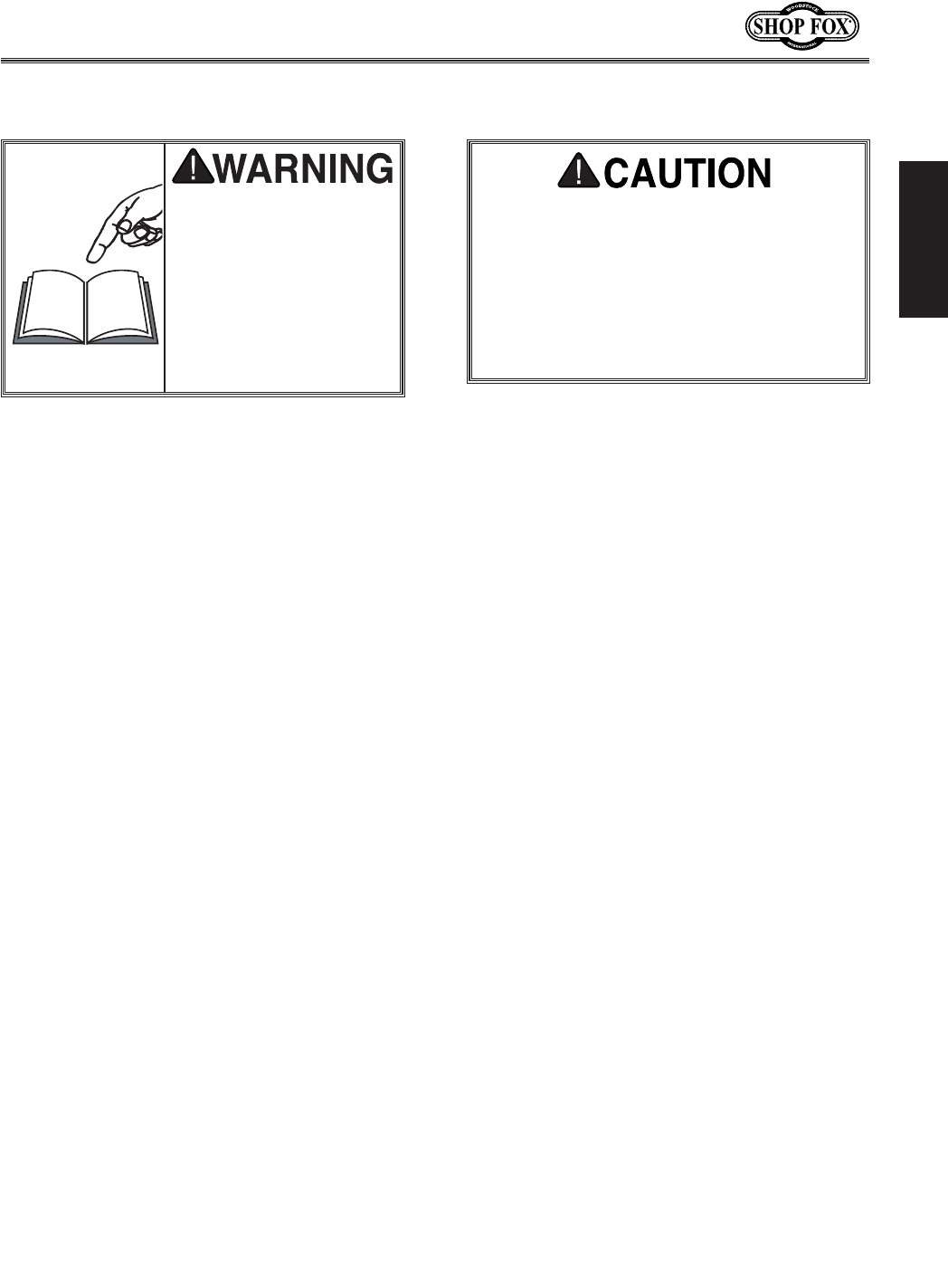
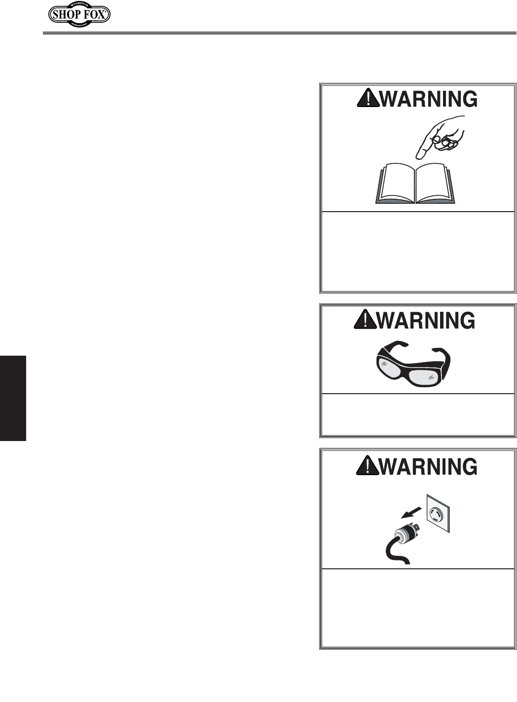
I<8;D8EL8C9<=FI<FG<I8K@E>D8:?@E<%
=8@CLI<KF=FCCFN@EJKIL:K@FEJ9<CFNN@CC
I<JLCK@EG<IJFE8C@EALIP%
JkXe[Xi[JX]\kp@ejkilZk`fej
(% I<8;K?IFL>?K?<<EK@I<D8EL8C9<=FI<JK8IK@E>D8:?@E<IP%DXZ_`e\ipgi\j\ekjj\i`flj
`ealip_XqXi[jkflekiX`e\[lj\ij%
)% 8CN8PJ LJ< 8EJ@ 8GGIFM<; J8=<KP >C8JJ<J N?<E FG<I8K@E> D8:?@E<IP% <m\ip[Xp \p\$
^cXjj\jfecp_Xm\`dgXZki\j`jkXekc\ej\jÇk_\pXi\EFKjX]\kp^cXjj\j%
*% 8CN8PJN<8I8E@FJ?8GGIFM<;I<JG@I8KFIN?<EFG<I8K@E>D8:?@E<IPK?8KGIF;L:<J
;LJK%Nff[[ljk`jXZXiZ`ef^\eXe[ZXeZXlj\ZXeZ\iXe[j\m\i\i\jg`iXkfip`cce\jj\j%
+% 8CN8PJ LJ< ?<8I@E> GIFK<:K@FE N?<E FG<I8K@E> D8:?@E<IP% DXZ_`e\ip ef`j\ ZXe ZXlj\
g\idXe\ek_\Xi`e^[XdX^\%
,% N<8IGIFG<I8GG8I<C%;FEFKn\Xicffj\Zcfk_`e^#^cfm\j#e\Zbk`\j#i`e^j#fia\n\cipn_`Z_dXp
^\kZXl^_k`edfm`e^gXikj%N\Xigifk\Zk`m\_X`iZfm\i`e^kfZfekX`ecfe^_X`iXe[n\Xiefe$jc`g
]ffkn\Xi%
-% E<M<IFG<I8K<D8:?@E<IPN?<EK@I<;#FILE;<IK?<@E=CL<E:<F=;IL>JFI8C:F?FC%
9\d\ekXccpXc\ikXkXcck`d\jn_\eilee`e^dXZ_`e\ip%
.% FECP8CCFNKI8@E<;8E;GIFG<ICPJLG<IM@J<;G<IJFEE<CKFFG<I8K<D8:?@E<IP%DXb\
jli\fg\iXk`fe`ejkilZk`fejXi\jX]\Xe[Zc\Xicple[\ijkff[%
/% B<<G:?@C;I<E8E;M@J@KFIJ8N8P%B\\gXccZ_`c[i\eXe[m`j`kfijXjX]\[`jkXeZ\]ifdk_\nfib
Xi\X%
0% D8B<NFIBJ?FG:?@C;GIFF=%Lj\gX[cfZbj#dXjk\ijn`kZ_\j#Xe[i\dfm\jkXikjn`kZ_b\pj%
@e[`ZXk\jXe`dd`e\ekcp_XqXi[fljj`klXk`fen_`Z_#`]efkXmf`[\[#N@CC
i\jlck`e[\Xk_fij\i`flj`ealip%
@e[`ZXk\jXgfk\ek`Xccp_XqXi[fljj`klXk`fen_`Z_#`]efkXmf`[\[#:FLC;
i\jlck`e[\Xk_fij\i`flj`ealip%
@e[`ZXk\jXgfk\ek`Xccp_XqXi[fljj`klXk`fen_`Z_#`]efkXmf`[\[#D8P
i\jlck`ed`efifidf[\iXk\`ealip%
K_`jjpdYfc`jlj\[kfXc\ikk_\lj\ikflj\]lc`e]fidXk`feXYflkgifg\i
fg\iXk`fef]k_\\hl`gd\ek#Xe[&fiXj`klXk`fek_XkdXpZXlj\[XdX^\
kfk_\dXZ_`e\ip%
EFK@:<

-8-
N(/((('Jc`[`e^KXYc\JXn
J8=<KP
('% E<M<IC<8M<N?<ED8:?@E<@JILEE@E>%Kliegfn\iF==Xe[XccfnXccdfm`e^gXikjkfZfd\kf
XZfdgc\k\jkfgY\]fi\c\Xm`e^dXZ_`e\leXkk\e[\[%
((% ;FEFKLJ<@E ;8E><IFLJ<EM@IFED<EKJ%;FEFKlj\dXZ_`e\ip`e[Xdg#n\kcfZXk`fej#fi
n_\i\Xep]cXddXYc\fiefo`flj]ld\jdXp\o`jk%
()% B<<GNFIB8I<8:C<8E8E;N<CCC@K%:clkk\iXe[[Xibj_X[fnjdXpZXlj\XZZ`[\ekj%
(*% LJ<8>IFLE;<;<OK<EJ@FE:FI;I8K<;=FIK?<D8:?@E<8DG<I8><%Le[\ij`q\[Zfi[jfm\i$
_\XkXe[cfj\gfn\i%I\gcXZ\\ok\ej`feZfi[j`]k_\pY\Zfd\[XdX^\[%;FEFKlj\\ok\ej`feZfi[j
]fi))'MdXZ_`e\ip%
(+% 8CN8PJ;@J:FEE<:K=IFDGFN<IJFLI:<9<=FI<J<IM@:@E>D8:?@E<IP%DXb\jli\jn`kZ_`j
`eF==gfj`k`feY\]fi\i\Zfee\Zk`e^%
(,% D8@EK8@ED8:?@E<IPN@K?:8I<%B\\gYcX[\jj_XigXe[Zc\Xe]fiY\jkXe[jX]\jkg\i]fidXeZ\%
=fccfn`ejkilZk`fej]ficlYi`ZXk`e^Xe[Z_Xe^`e^XZZ\jjfi`\j%
(-% D8B<JLI<>L8I;J8I<@EGC8:<8E;NFIB:FII<:KCP9<=FI<LJ@E>D8:?@E<IP%
(.% I<DFM< 8;ALJK@E> B<PJ 8E; NI<E:?<J% DXb\ X _XY`k f] Z_\Zb`e^ ]fi b\pj Xe[ X[aljk`e^
ni\eZ_\jY\]fi\klie`e^dXZ_`e\ipFE%
(/% :?<:B =FI ;8D8><; G8IKJ 9<=FI< LJ@E> D8:?@E<IP% :_\Zb ]fi Y`e[`e^ Xe[ Xc`^ed\ek f]
gXikj#Yifb\egXikj#gXikdflek`e^#cffj\Yfckj#Xe[Xepfk_\iZfe[`k`fejk_XkdXpX]]\ZkdXZ_`e\
fg\iXk`fe%I\gX`ifii\gcXZ\[XdX^\[gXikj%
(0% LJ<I<:FDD<E;<;8::<JJFI@<J%I\]\ikfk_\`ejkilZk`fedXelXc]fii\Zfdd\e[\[XZZ\jjfi`\j%
K_\lj\f]`dgifg\iXZZ\jjfi`\jdXpZXlj\i`jbf]`ealip%
)'%;FEFK=FI:<D8:?@E<IP%NfibXkk_\jg\\[]fin_`Z_k_\dXZ_`e\fiXZZ\jjfipnXj[\j`^e\[%
)(% J<:LI< NFIBG@<:<% Lj\ ZcXdgj fi X m`j\ kf _fc[ k_\ nfibg`\Z\ n_\e giXZk`ZXc% 8 j\Zli\[
nfibg`\Z\gifk\Zkjpfli_Xe[jXe[]i\\jYfk__Xe[jkffg\iXk\k_\dXZ_`e\%
))% ;FEFKFM<II<8:?%B\\ggifg\i]ffk`e^Xe[YXcXeZ\XkXcck`d\j%
)*% D8EPD8:?@E<JN@CC<A<:KK?<NFIBG@<:<KFN8I;K?<FG<I8KFI%BefnXe[Xmf`[Zfe[`$
k`fejk_XkZXlj\k_\nfibg`\Z\kfb`ZbYXZb%
)+% 8CN8PJCF:BDF9@C<98J<J@=LJ<; 9<=FI<FG<I8K@E>D8:?@E<IP%
),%9< 8N8I< K?8K :<IK8@E ;LJK D8P 9< ?8Q8I;FLJ kf k_\ i\jg`iXkfip jpjk\dj f] g\fgc\ Xe[
Xe`dXcj#\jg\Z`Xccp]`e\[ljk%DXb\jli\pflbefnk_\_XqXi[jXjjfZ`Xk\[n`k_k_\kpg\f][ljkpfl
n`ccY\\ogfj\[kfXe[XcnXpjn\XiXi\jg`iXkfiXggifm\[]fik_Xkkpg\f][ljk%
-9-
N(/((('Jc`[`e^KXYc\JXn
J8=<KP
8[[`k`feXcJX]\kp]fiJc`[`e^KXYc\JXnj
I<8;Xe[le[\ijkXe[k_`j
\ek`i\ `ejkilZk`fe dXelXc
Y\]fi\lj`e^k_`jdXZ_`e\%
J\i`flj g\ijfeXc `ealip
dXp fZZli `] jX]\kp Xe[
fg\iXk`feXc`e]fidXk`fe`j
efk le[\ijkff[ Xe[ ]fc$
cfn\[% ;F EFK i`jb pfli
jX]\kpYpefki\X[`e^
(% J8=<KP 8::<JJFI@<J% Always use the blade guard and riving knife on all ''through-sawing'' opera-
tions. K_ifl^_$jXn`e^fg\iXk`fejXi\k_fj\n_\ek_\YcX[\ZlkjZfdgc\k\cpk_ifl^_k_\nfibg`\Z\%
)% B@:B98:B%Be familiar with kickback. Kickback happens when the workpiece is thrown towards the
operator at a high rate of speed. Lek`cpfl_Xm\XZc\Xile[\ijkXe[`e^f]b`ZbYXZbXe[_fn`kfZZlij#
;FEFKfg\iXk\k_`jkXYc\jXn
*% NFIBG@<:<:FEKIFC% Make sure the workpiece is placed in a stable position on the table and is
either supported by the rip fence or the crosscut table during cutting operations.
+% GLJ?JK@:B% Always use a push stick when ripping narrow stock.
,% FG<I8KFIGFJ@K@FE% Never stand or have any part of your body directly in-line with the cutting path
of the saw blade.
-% I<8:?@E>FM<IJ8N9C8;<% Never reach behind or over the blade with either hand while the saw
is running. @]b`ZbYXZbfZZlijn_`c\i\XZ_`e^fm\ik_\YcX[\#_Xe[jfiXidjZflc[Y\glcc\[`ekfk_\
jg`ee`e^jXnYcX[\%
.% LJ@E>K?<I@G=<E:<8E; K?<:IFJJ:LK=<E:<KF><K?<I;LI@E> 8:LKK@E> FG<I8K@FE%
When using the crosscut fence, the workpiece should never be contacting the rip fence while the saw
blade is cutting.
/% JK8CC<;9C8;<% Turn the saw F== before attempting to "free" a stalled saw blade.
0% :FD=FIK89C<:LKK@E>FG<I8K@FEJ% Avoid awkward operations and hand positions where a sud-
den slip could cause your hand to move into the spinning saw blade.
('%<OG<I@<E:@E>;@==@:LCK@<J%If at any time you are experiencing difficulties performing the intend-
ed operation, stop using the machine! Contact Tech Support at (360) 734-3482.
((% 9C8;< ?<@>?K% DO NOT make cuts with the blade height more than 1⁄4" above the top of the
workpiece, or the operator will be unnecessarily exposed to the blade during the cut.
()%;8D8><;J8N9C8;<J% Never use blades that have been dropped or otherwise damaged.
(*%I@M@E>BE@=<8C@>ED<EK%Only operate the saw if the riving knife is aligned with the main blade.
LJ<k_`jXe[fk_\idXZ_`e\ipn`k_ZXlk`fe
Xe[ i\jg\Zk% 8cnXpj Zfej`[\i jX]\kp ]`ijk#
Xj `k Xggc`\j kf pfli `e[`m`[lXc nfib`e^
Zfe[`k`fej%Efc`jkf]jX]\kp^l`[\c`e\jZXe
Y\ Zfdgc\k\Ç\m\ip j_fg \em`ifed\ek `j
[`]]\i\ek%=X`cli\kf]fccfn^l`[\c`e\jZflc[
i\jlck `e j\i`flj g\ijfeXc `ealip# [XdX^\
kf\hl`gd\ekfigffinfibi\jlckj%

-10-
N(/((('Jc`[`e^KXYc\JXn
J8=<KP
9\cfnXi\gi\m\ekXk`m\d\Xli\jkfXmf`[k_\
dfjkZfddfeZXlj\jf]b`ZbYXZb1
• Only cut workpieces with at least one
smooth and straight edge. DO NOT cut
warped, cupped or twisted wood.
• Never attempt freehand cuts. If the
workpiece is not fed parallel with the
blade, kickback will likely occur. Always use
the rip fence or miter gauge to support the
workpiece.
• Make sure the splitter/riving knife is
aligned with the blade. A misaligned split-
ter/riving knife can cause the workpiece
to catch or bind, increasing the chance of
kickback. If you think that your splitter or
riving knife is not aligned with the blade,
check it immediately!
• Take the time to check and adjust the rip
fence parallel with the blade. Also, ensure
that your table slides parallel with the
blade. If either of these two elements are
not adjusted correctly, the risk of kickback
will be greatly increased.
• Do not remove the splitter/riving knife.
The splitter/riving knife maintains the kerf
in the workpiece, reducing the chance of
kickback from the workpiece halves pinch-
ing the blade.
• Feed cuts through to completion. Anytime
you stop feeding a workpiece in the middle
of a cut, the chance of kickback is greatly
increased.
• Keep the blade guard installed and in good
working order. Only remove it when per-
forming non-through cuts and immediately
re-install the blade guard when finished.
Remember, always use the riving knife for
all non-through operations, unless a dado
blade is installed.
• Make multiple, shallow passes when per-
forming a non-through cut. Making a deep
non-through cut will greatly increase the
chance of kickback.
JkXk`jk`Zj j_fn k_Xk dfjk Zfddfe XZZ`$
[\ekjXdfe^kXYc\jXnlj\ijZXeY\c`eb\[
kf b`ZbYXZb% B`ZbYXZb `j kpg`ZXccp [\]`e\[
Xjk_\_`^_$jg\\[\oglcj`fef]jkfZb ]ifd
k_\kXYc\jXnkfnXi[`kjfg\iXkfi%@eX[[`$
k`fekfk_\[Xe^\if]k_\fg\iXkfififk_\ij
`ek_\Xi\XY\`e^jkilZbYpk_\]cp`e^jkfZb#
`k `j f]k\e k_\ ZXj\ k_Xk k_\ fg\iXkfiËj
_Xe[jXi\glcc\[`ekfk_\YcX[\[li`e^k_\
b`ZbYXZb%
Gi\m\ek`e^B`ZbYXZb
Even if you know how to prevent kickback, it
may still happen.
?\i\Xi\jfd\gi\m\ekXk`m\d\Xli\jkf
gifk\Zkpflij\c]`]b`ZbYXZb;F<JfZZli1
• Stand to the side of the blade during every
cut. If a kickback does occur, the thrown
workpiece usually travels directly in front
of the blade.
• Wear safety glasses or a face shield. In the
event of a kickback, your eyes and face are
the most vulnerable part of your body.
• Never, for any reason, place your hand
behind the blade. Should kickback occur,
your hand will be pulled into the blade.
• Use a push stick to keep your hands farther
away from the moving blade. If a kickback
occurs, the push stick will most likely take
the damage that your hand would have
received.
• Keep the blade guard installed and in good
working order.
• Use featherboards or anti-kickback devices,
such as Shop Fox Board Buddies, to prevent
or slow down kickback.
Gifk\Zk`e^Pflij\c]
=ifdB`ZbYXZb

-11-
N(/((('Jc`[`e^KXYc\JXn
J8=<KP
The following is a list of common definitions, terms and phrases used throughout this manual as they relate
to this table saw and woodworking in general. Become familiar with these terms for assembling, adjusting
or operating this machine.
8iYfi1 A metal shaft extending from the drive
mechanism that is the mounting location for the
saw blade.
9\m\c<[^\:lk1 Tilting the arbor and saw
blade to an angle between 0˚ and 45˚ to cut a
beveled edge onto a workpiece.
9cX[\>lXi[8jj\dYcp1 Metal or plastic safety
device that mounts over the saw blade. Its
function is to prevent the operator from coming
into contact with the saw blade. Refer to GX^\
** for more details.
:ifjjZlk1 Cutting operation in which the
crosscut fence is used to cut across the shortest
width of the workpiece. Refer to GX^\+) for
more details.
;X[f9cX[\1 Blade or set of blades that are
used to cut grooves and rabbets. DO NOT use
a dado blade larger than 8" in diameter on this
saw! The saw and arbor are not intended to
safely use a larger dado blade.
;X[f:lk1 Cutting operation that uses a dado
blade to cut a flat bottomed groove into the
face of the workpiece. Refer to GX^\+, for
more details.
=\Xk_\iYfXi[1 Safety device used to keep the
workpiece against the rip fence and against
the table surface. Refer to GX^\,( for more
details.
B\i]1 The resulting cut or gap in the workpiece
after the saw blade passes through during a
cutting operation.
B`ZbYXZb1 An event in which the workpiece is
propelled back towards the operator at a high
rate of speed.
Efe$K_ifl^_:lk1 A cut in which the blade
does not cut through the top of the workpiece.
Refer to GX^\*) for more details.
GXiXcc\c1 Being an equal distance apart at every
point along two given lines or planes (i.e. the
rip fence face is parallel to the face of the saw
blade).
G\ig\e[`ZlcXi1 Lines or planes that intersect
and form right angles (i.e. the blade is
perpendicular to the table surface).
Glj_Jk`Zb1 Safety device used to push the
workpiece through a cutting operation. Used
most often when rip cutting thin workpieces.
Refer to GX^\,( for more details.
IXYY\k1 Cutting operation that creates an
L-shaped channel along the edge of the
workpiece. Refer to GX^\+. for more details.
I`g:lk1 Cutting operation in which the rip
fence is used to cut across the width of the
workpiece. Refer to GX^\+' for more details.
I`m`e^Be`]\1 Metal plate located behind the
blade. It maintains the kerf opening in the wood
when performing a cutting operation. Refer to
GX^\*+ for more details.
JkiX`^_k\[^\1 A tool used to check the flatness,
parallelism, or consistency of a surface(s).
K_`eB\i]9cX[\1 A blade with a kerf or
thickness that is thinner than a standard blade.
Since thin kerf blades are typically the same
thickness of the splitter or riving knife—and in
some cases thinner—we DO NOT recommend
that they be used on this saw due to the
increased risk of kickback.
K_ifl^_:lk1A cut in which the blade cuts
completely through the workpiece. Refer to
GX^\*) for more details.
Q\if:c\XiXeZ\KXYc\@ej\ik1 An aftermarket or
shop-made table insert specifically modified for
the installed blade to eliminate clearance around
the blade.
>cfjjXipF]K\idj
-12-
N(/((('Jc`[`e^KXYc\JXn
<C<:KI@:8C
<C<:KI@:8C
))'MJ`e^c\$G_Xj\
Fg\iXk`fe
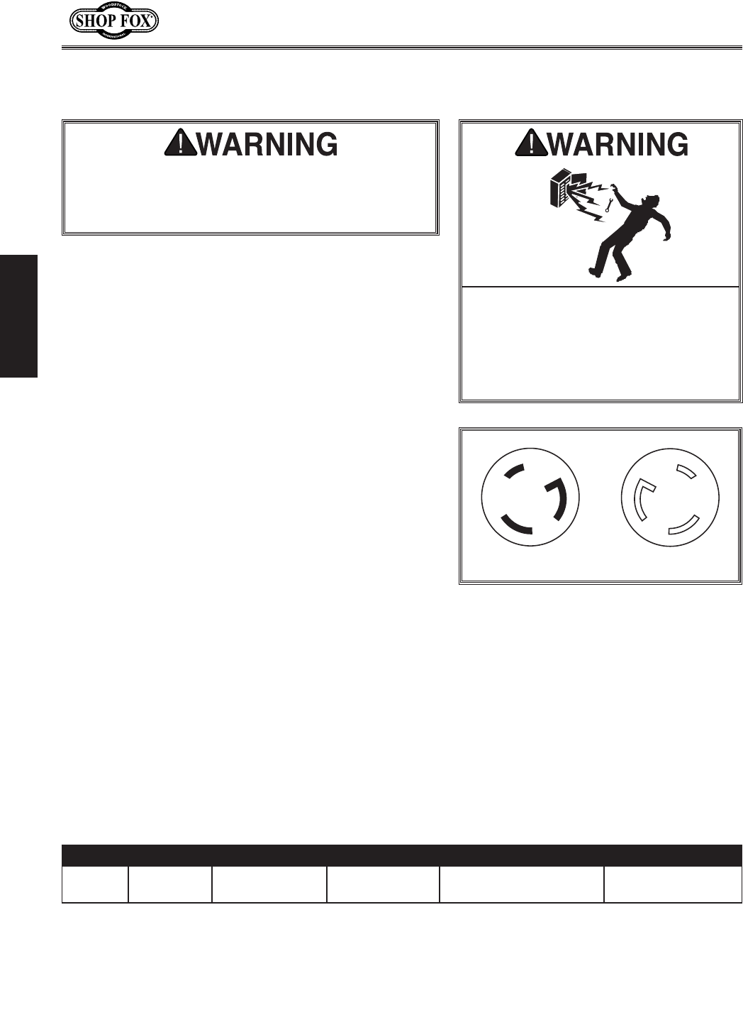
L6-30 P L6-30 R
=`^li\)% L6-30 Plug and outlet.
MfckX^\ 8dg;iXn D`e%:`iZl`kJ`q\ :fee\Zk`fe :fi[ <ok\ej`fe:fi[
220V 22A 30A L6-30 Plug 10/3 AWG, 300 VAC 10/3 AWG
(not to exceed 50')
<c\Zki`ZXcJg\Z`]`ZXk`fej
K_\dXZ_`e\dljkY\gifg\icpj\klgY\]fi\`k`jjX]\
kf fg\iXk\% ;F EFK _Xm\ pfli \c\Zki`Z`Xe Zfee\Zk
k_`jdXZ_`e\kfk_\gfn\ijfliZ\lek`c`ejkilZk\[kf
[fjfcXk\i`ek_`jdXelXc%
;FEFKnfibfepfli\c\Zki`ZXcjpjk\d
`] pfl Xi\ lejli\ XYflk \c\Zki`ZXc
Zf[\jXe[n`i`e^J\\bXjj`jkXeZ\]ifd
X hlXc`]`\[ \c\Zki`Z`Xe% @^efi`e^ k_`j
nXie`e^ZXeZXlj\\c\ZkifZlk`fe#]`i\#
fidXZ_`e\[XdX^\%
The Model W1811 is wired for 220V single-phase operation.
We recommend connecting this machine to a dedicated
circuit with a verified ground, using the circuit size given
below. Never replace a circuit breaker with one of higher
amperage without consulting a qualified electrician to
ensure compliance with wiring codes. This machine must
be connected to a grounded circuit!
A plug is not supplied with this machine. See below for
the recommended plug type for this machine.
@]pflXi\lejli\XYflkk_\n`i`e^Zf[\j`epfliXi\X
fipflgcXekfZfee\ZkpflidXZ_`e\kfXj_Xi\[Z`i$
Zl`k#pfldXpZi\Xk\X]`i\fiZ`iZl`kfm\icfX[_XqXi[Ç
ZfejlckXhlXc`]`\[\c\Zki`Z`Xekfi\[lZ\k_`ji`jb%
We do not recommend using an extension cord; however,
if you have no alternative, use the following guidelines:
• Use a cord rated for Standard Service (S).
• Do not use an extension cord longer than 50 feet.
• Ensure that the cord has a ground wire and pin.
• Use the gauge size listed below as a minimum.
<ok\ej`fe:fi[j
-13-
N(/((('Jc`[`e^KXYc\JXn
J<KLG
B\\g dXZ_`e\ [`jZfee\Zk\[ ]ifd
gfn\ilek`c`ejkilZk\[fk_\in`j\%
This machine has been carefully packaged for safe
transportation. If you notice the machine has been
damaged during shipping, please contact your authorized
Shop Fox dealer immediately.
LegXZb`e^
J<KLG
The following items are needed to complete the setup
process, but are not included with your machine:
;\jZi`gk`fe Hkp
• Safety Glasses (for each person) ........................1
• Forklift ......................................................1
• Lifting Straps (2000 lb capacity) ........................2
• An Assistant .................................................1
• Straightedge 4' (or longer) ...............................1
• Table Saw Blade 10" .......................................1
• Phillips Head Screwdriver #2 ............................1
• Hex Wrenches 3, 4, 5, 6, & 8mm ................1 Each
• Dust Collection System ...................................1
• 4" Dust Hose (length as needed) ........................1
• 4" Hose Clamp ..............................................2
• 2½" Dust Hose (length as needed) ......................1
@k\djE\\[\[]fiJ\klg
-14-
N(/((('Jc`[`e^KXYc\JXn
J<KLG
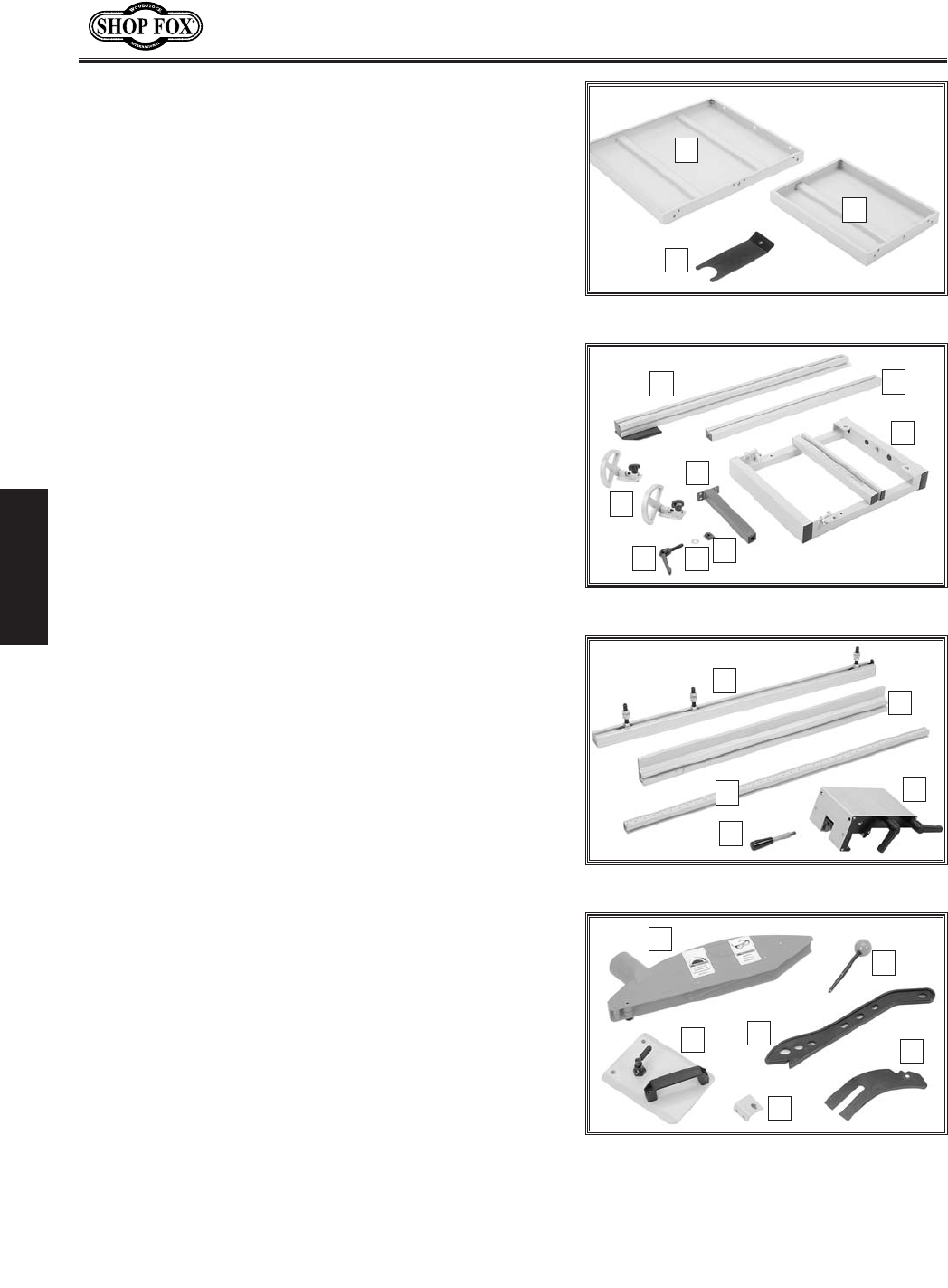
The following is a description of the main components
shipped with the Model W1811. If you can't find an
item on this list, check the mounting location on the
machine or examine the packaging materials carefully.
Occasionally we pre-install certain components for
safer shipping. If you still can't find a part, talk to your
authorized Shop Fox dealer.
@em\ekfip:fek\ekj
@em\ekfip@k\d1=`^li\j*Æ- Hkp
8% Table Saw (not shown) ....................................1
9% Large Extension Table.....................................1
:% Small Extension Table .....................................1
;% Hose Support ...............................................1
<% Crosscut Fence .............................................1
=% Support Bar .................................................1
>% Crosscut Table ..............................................1
?% Crosscut Table Support Leg ..............................1
@% Flip Stops ...................................................2
A% Lock Lever M12-1.75 x 55 ................................1
B% Flat Washer 12mm.........................................1
C% T-Nut M12-1.75 .............................................1
D% Rip Fence Rail (w/Attached Mounting Hardware) .....1
E% Rip Fence ...................................................1
F% Rip Fence Scale ............................................1
G% Rip Fence Lever w/Hex Nut M8-1.25 ....................1
H% Rip Fence Base .............................................1
I% Blade Guard w/Cap Screw & Nut ........................1
J% Arbor Lock Tool ............................................1
K% Sliding Table Handle w/Lock .............................1
L% Push Stick ...................................................1
M% Riving Knife .................................................1
N% End Cover ...................................................1
O% Wrench 17mm (not shown) ...............................1
P% Wrench 19/22mm (not shown) ...........................1
@em\ekfip
=`^li\*%Extension table items.
B
C
D
=`^li\+%Crosscut table items.
EF
I
G
L
K
J
H
=`^li\,%Rip fence items.
N
O
M
P
Q
=`^li\-% Miscellaneous components.
R
S
V
T
W
U
-15-
N(/((('Jc`[`e^KXYc\JXn
J<KLG
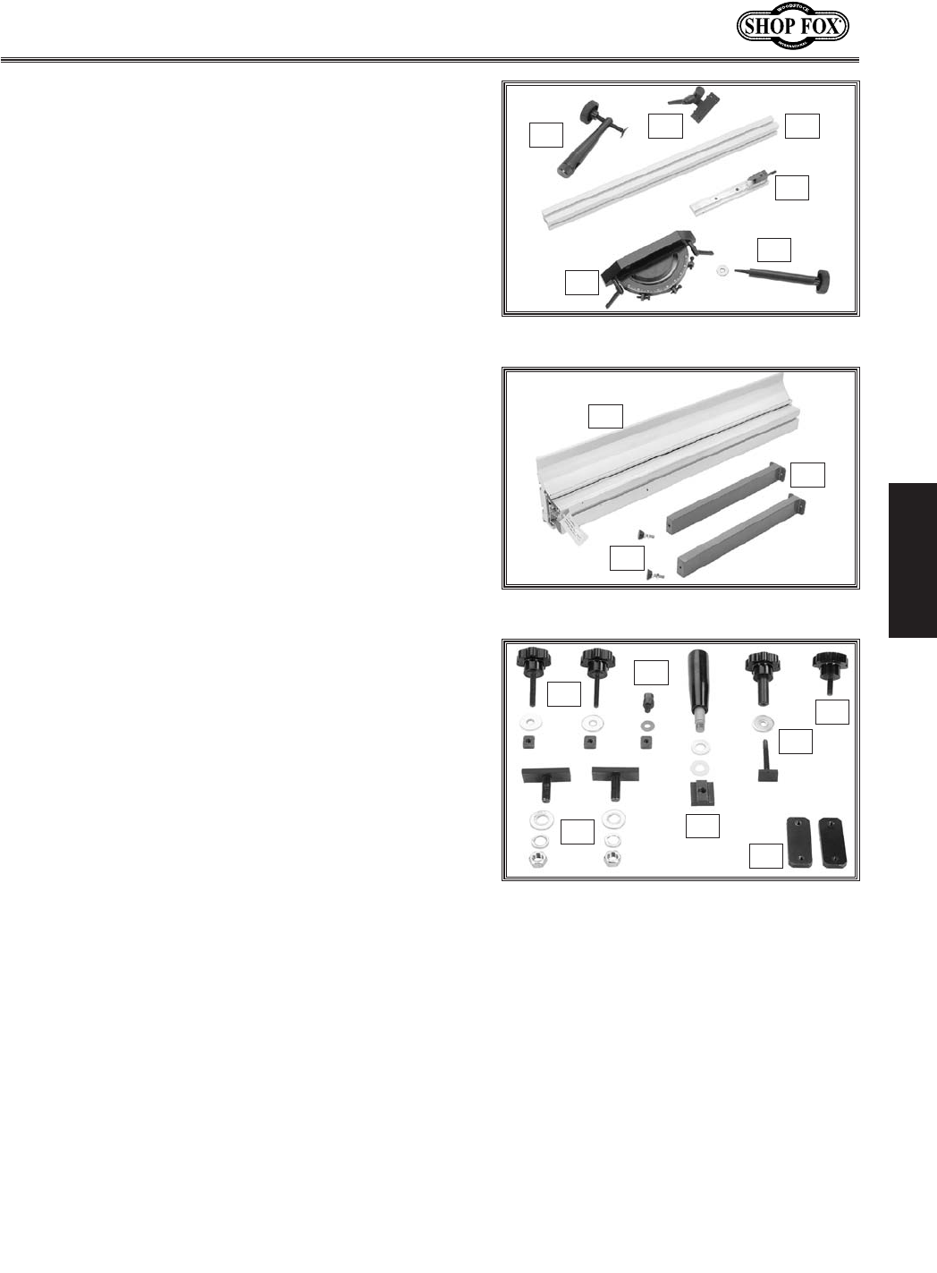
@em\ekfip@k\d1=`^li\.Æ0 Hkp
88% Miter Clamp ................................................1
89% Miter Flip Stop .............................................1
8:% Miter Handle w/Flat Washer 8mm ......................1
8;% Miter Gauge Fence ........................................1
8<% Miter Gauge Body ..........................................1
8=% Miter Guide Bar ............................................1
8>%Sliding Table ................................................1
8?%Sliding Table Support Legs ...............................2
8@% Feet M12-1.75 x 75 w/Nuts ..............................2
8A% Crosscut Brace Knobs M8-1.25 x 50 .....................2
—Flat Washers 8mm .......................................2
—Square Nuts M8-1.25 ....................................2
8B% Crosscut Fence Knob M8-1.25 ...........................1
—Flat Washer 8mm ........................................1
—Crosscut Fence T-Stud M8-1.25 x 60 ..................1
8C% Crosscut Fence Lock Knob M8-1.25 x 25 ...............1
8D% Pivot Stud ...................................................1
—Special Washer 8 x 20mm ..............................1
—Square Nut M8-1.25 .....................................1
8E% Push Handle M12-1.75 x 14 ..............................1
—Flat Washer 12mm.......................................1
—Plastic Washer 12mm ...................................1
—Push Handle T-Nut M12-1.75 ...........................1
8F% Support Leg T-Slot Plates ................................2
8G%Sliding Table T-Studs M12-1.75 x 35 ....................2
—Flat Washers 12mm .....................................2
—Lock Washers 12mm .....................................2
—Hex Nuts M12-1.75 ......................................2
Fk_\i?Xi[nXi\efkj_fne Hkp
• Cap Screws M10-1.5 x 25 (Extension Tables) ..........5
• Flat Washers 10mm (Extension Tables) ................5
• Lock Washers 10mm (Extension Tables) ................5
• Set Screws M8-1.25 x 25 (Extension Tables) ..........6
• Hex Nuts M8-1.25 (Extension Tables) ...................6
• Hex Bolts M6-1 x 16 (Fence Scale)......................2
• Hex Bolt M6-1 x 25 (Fence Scale) .......................1
• Flat Washers 6mm (Fence Scale) .......................3
• Lock Washers 6mm (Fence Scale) .......................3
• Hex Nuts M6-1 (Fence Scale) ............................3
• Cap Screws M6-1 x 16 (CT Support Leg) ...............4
• Lock Washers 6mm (CT Support Leg) ..................4
• Flat Washers 6mm (CT Support Leg) ...................4
• Cap Screws M5-.8 x 12 (Switch) .........................2
• Lock Washers 5mm (Switch) .............................2
• Cap Screws M10-1.5 x 30 (ST Leg Plates) ..............4
• Lock Washers 10mm (ST Leg Plates) ...................4
• Cap Screw M10-1.5 x 25 (Hose Support) ...............1
• Flat Washers 10mm (Hose Support) ....................2
• Hex Nut M10-1.5 (Hose Support) ........................1
=`^li\.%Miter gauge items.
AA
AC
AD
AE
AF
AB
=`^li\/% Sliding table items.
AG
AH
AI
=`^li\0% Miscellaneous knobs and
hardware.
AJ
AK
AL
AM
AN
AO
AP
-16-
N(/((('Jc`[`e^KXYc\JXn
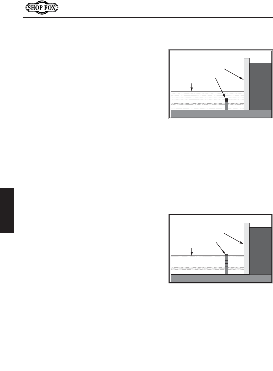
J<KLG
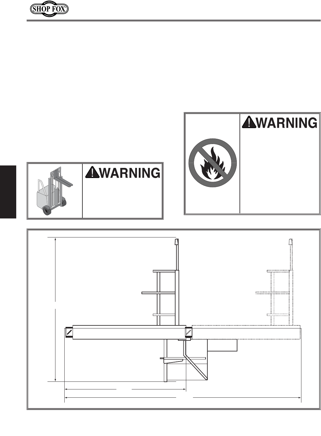
=cffiCfX[1 This machine distributes a
heavy load in a small footprint. Make
sure the floor will support the machine,
workpieces, and the operator.
Nfib`e^:c\XiXeZ\j1 Consider existing and
anticipated needs, size of material to be
processed through the machine, and space
for auxiliary stands, work tables or other
machinery when establishing a location for
your machine (see =`^li\(').
C`^_k`e^1 Lighting should be bright enough
to eliminate shadows and prevent eye
strain.
:c\Xe`e^DXZ_`e\
The table and other unpainted parts of your
machine are coated with a waxy grease that
protects them from corrosion during shipment.
Clean this grease off with a solvent cleaner or
citrus-based degreaser. DO NOT use chlorine-
based solvents such as brake parts cleaner or
acetone—if you happen to splash some onto a
painted surface, you will ruin the finish.
DXZ_`e\GcXZ\d\ek
LJ< _\cg\ij Xe[ gfn\i
c`]k`e^ \hl`gd\ek kf c`]k
k_`j dXZ_`e\% Fk_\in`j\#
j\i`flj g\ijfeXc `ealip
dXpfZZli%
E<M<IZc\Xen`k_^Xjfc`e\
fi fk_\i g\kifc\ld$
YXj\[jfcm\ekj%Dfjk_Xm\
cfn ]cXj_ gf`ekj# n_`Z_
dXb\ k_\d \oki\d\cp
]cXddXYc\% 8 i`jb f]
\ogcfj`fe Xe[ Ylie`e^
\o`jkj `] k_\j\ gif[lZkj
Xi\lj\[%J\i`fljg\ijfeXc
`ealip dXp fZZli `] k_`j
nXie`e^`j`^efi\[
()*
(,'
.(
=`^li\('% Working clearances.
-17-
N(/((('Jc`[`e^KXYc\JXn
J<KLG
Kfi\dfm\k_\kXYc\jXn]ifdk_\ZiXk\gXcc\k#[f
k_\j\jk\gj1
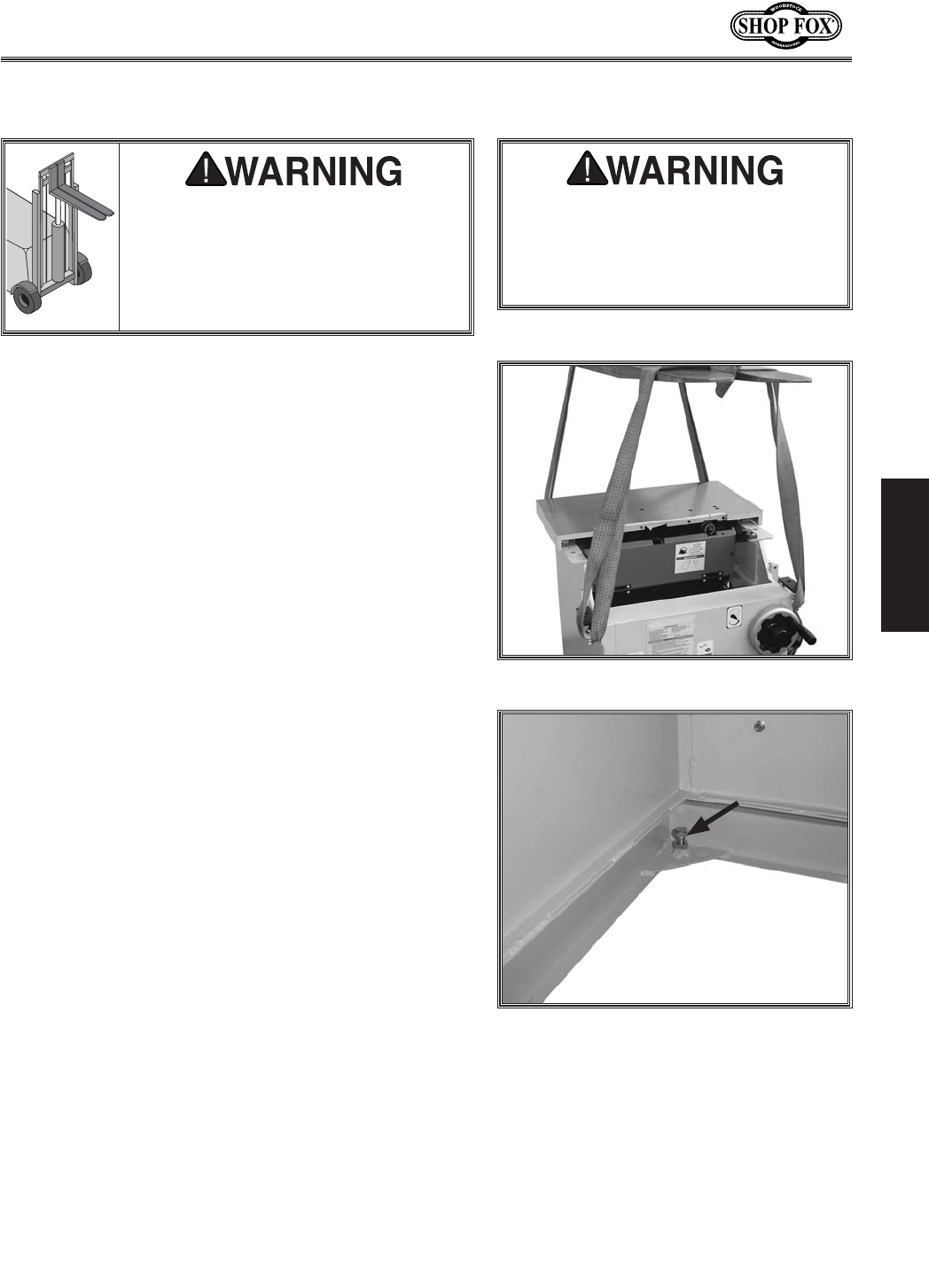
(% Feed the lifting straps around the lifting bolts on the
back of the table and the sliding table saw mounts
on the front of the cabinet (see =`^li\((). Attach
the ends of the lifting straps to the forklift forks.
)% Lift the table saw cabinet and move it to your pre-
determined location.
*% Remove the red lifting bolts from the back of the
table.
C`]k`e^Dfm`e^
K_`jdXZ_`e\n\`^_jfm\i,''cYj%
J\i`fljg\ijfeXc`ealipdXpfZZli`]
jX]\dfm`e^d\k_f[jXi\efk]fccfn\[%
Kf Y\ jX]\# pfl n`cc e\\[ Xk c\Xjk fe\
fk_\ig\ijfeXe[X]fibc`]kkfdfm\Xe[
gcXZ\k_`jdXZ_`e\%
Lj\c`]k`e^jkiXgjn`k_Xd`e`dldc`]k`e^
ZXgXZ`kp _`^_\i k_Xe k_\ jXn n\`^_k%
;FEFK c`]kjXn_`^_\ik_Xee\Z\jjXip
kfZc\Xi]cffi%@]c`]k`e^jkiXgYi\Xbj#
j\i`fljg\ijfeXc`ealipdXpfZZli%
=`^li\((% Lifting the table saw.
=`^li\()% Hex bolt in stand corners for
leveling; the hex nut is used to secure the
bolt position.
+% Place a level on the cast iron table to level the table
saw cabinet side-to-side and front-to-back. This will
allow the table to slide smoothly.
Efk\1 K_\i\Xi\knffgk`fej]fic\m\c`e^k_\jXn1
( J_`dle[\ik_\ZXY`e\k#fi) k_i\X[Yfckj[fne
`ekfk_\elkjn\c[\[fek_\jkXe[Zfie\ij=`^li\
() %
-18-
N(/((('Jc`[`e^KXYc\JXn
J<KLG
Before shipping, the sliding table was installed on the
machine and calibrated to the main table and blade. As
such, be careful not to move any pre-installed nuts when
installing the sliding table.
The sliding table and extension tables are heavy, so use
a forklift or four strong helpers to lift the sliding table
during installation.
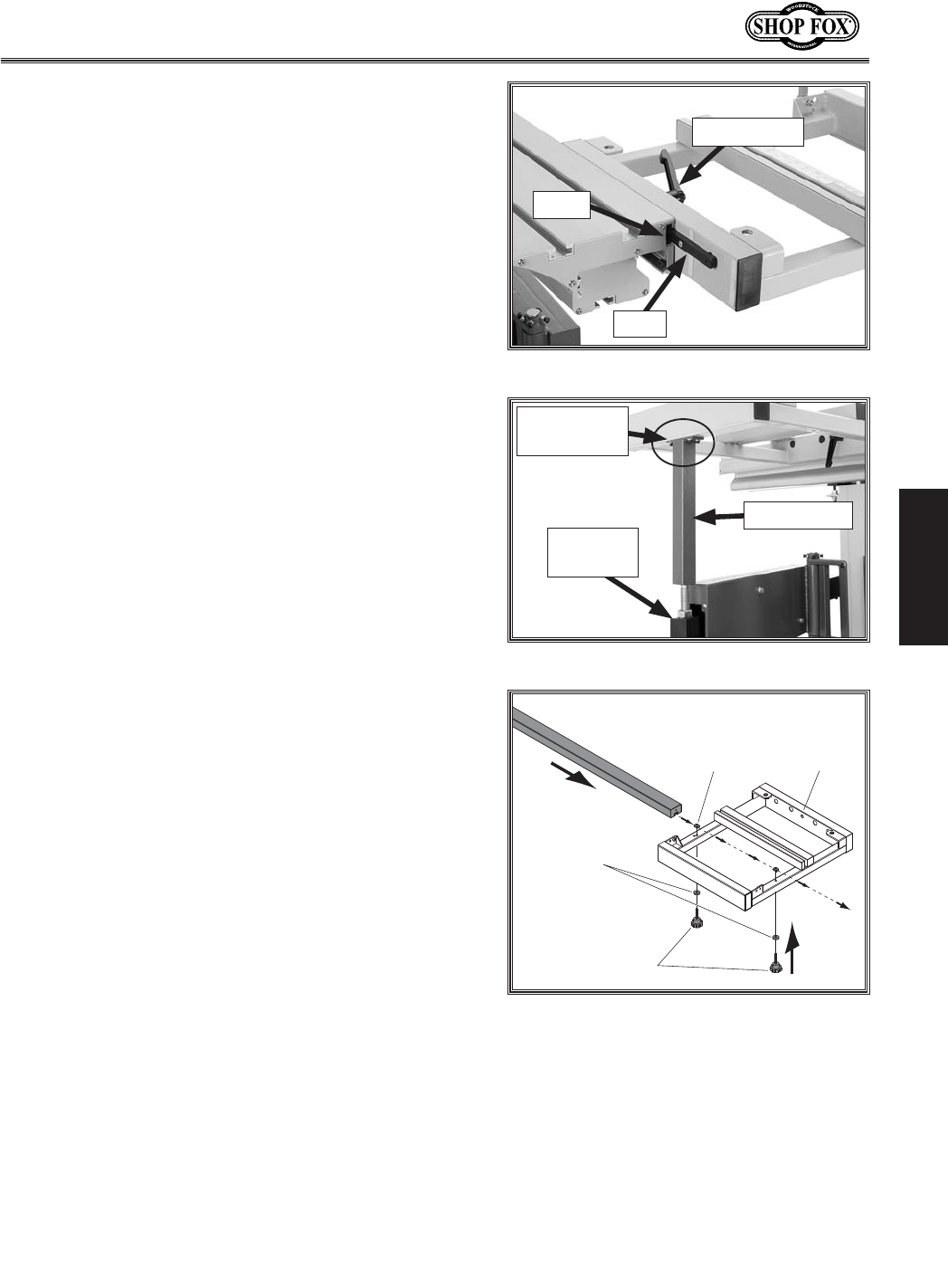
KfXjj\dYc\k_\jc`[`e^kXYc\jXn#[fk_\j\jk\gj1
(. Place the sliding table on the cabinet.
). On each side of the sliding table, slide a T-stud
down the center bottom T-slot until it is next to the
mounting bracket.
*. Lift one side of the sliding table, position the T-stud
over the hole in the mounting bracket, then lower
the sliding table so the T-stud fits through the hole,
as shown in =`^li\(*. Repeat on the other side.
+. Put a 12mm flat washer, 12mm lock washer and M12-
1.75 hex nut on the bottom of each T-stud and tight-
en the hex nut to secure the sliding table in place.
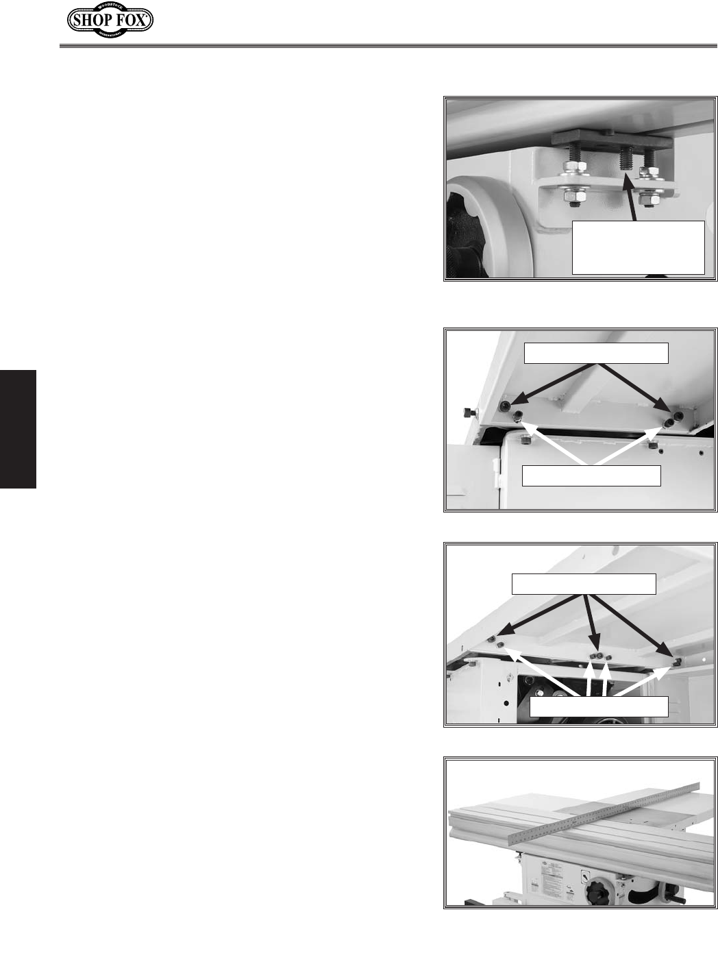
,. Install the small extension table with the two M10-
1.5 x 25 cap screws, 10mm flat washers and 10mm
lock washers (see =`^li\(+).
-% Thread one M8-1.25 hex nut halfway onto each of
the M8-1.25 x 25 set screws, then install two of the
set screws where shown in =`^li\(+, to act as lev-
eling screws in a later step.
.% Install the large extension table with the three M10-
1.5 x 25 cap screws, 10mm flat washers, and 10mm
lock washers (see =`^li\(,).
/% Thread four M8-1.25 x 25 set screws with hex nuts
where shown in =`^li\(,, to act as leveling set
screws in a later step.
0% Level the top of the extension tables even with the
top of the cast iron table.
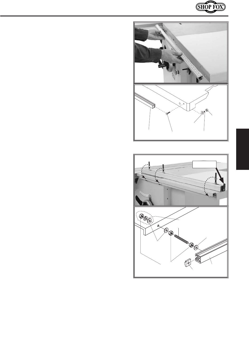
Using a straightedge as a guide (=`^li\(-), adjust
the leveling set screws to align the top of the exten-
sion tables with the top of the cast iron table.
Tighten the hex nuts on the leveling screws against
the extension table to lock the screws when the
tables are aligned.
8jj\dYcpJ\klg
=`^li\(*% T-stud inserted in mounting
bracket.
T-Stud Inserted
Through Mounting
Bracket
=`^li\(+% Small extension table installed.
Mounting Cap Screws
Leveling Set Screws
=`^li\(,% Large extension table installed.
Mounting Cap Screws
Leveling Set Screws
=`^li\(-% Extension wings mounted and
even with cast iron table.
-19-
N(/((('Jc`[`e^KXYc\JXn
J<KLG
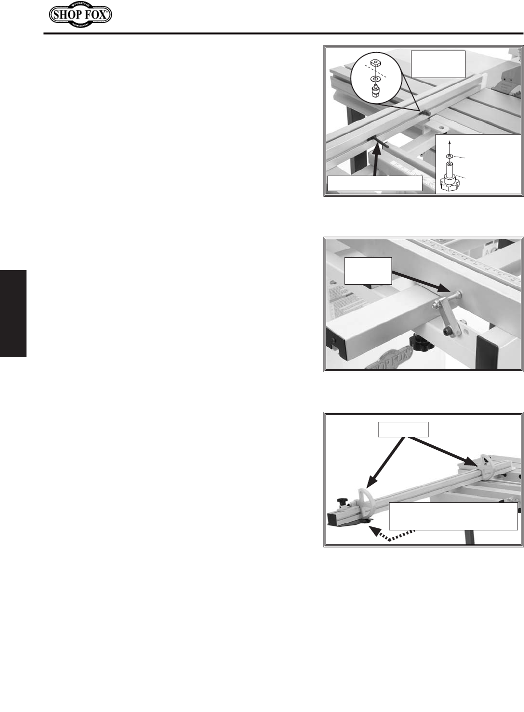
('% Mount the rip fence scale to the large extension
table and cast iron table (=`^li\(.) using three
M6-1 hex nuts, 6mm lock washers, 6mm flat wash-
ers, two M6-1 x 16 hex bolts, and one M6-1 x 25 hex
bolt. (The longer hex bolt is used in the cast iron
table.) Adjust the scale even with the table tops,
then tighten the fasteners.
=`^li\(.% Mounting rip fence scale.
JZXc\ ?\o9fck
?\o
Elk
CfZbNXj_\i
=cXk
NXj_\i
KXYc\
=`^li\(/% Rip fence rail mounting.
IX`c
K$Elk
D()$(%.,
?\oElk
Jkl[D()$(%.,o0'
()dd
=cXkNXj_\i
()dd=cXkNXj_\i
()ddCfZbNXj_\i
Black Tab
((% Mount the rip fence rail as shown in =`^li\(/. Make
sure the black tab is toward the back end of the
saw. Adjust the hex nuts so the gap between the rail
and tables is even, but leave the rail slightly loose
for now.
-20-
N(/((('Jc`[`e^KXYc\JXn
J<KLG
()% Slide the rip fence base on the rail, and check the
spacing between the rip fence base and scale bar
(see =`^li\(0). There should be a minimum of 1⁄8"
of space between the scale bar and the fence base.
Adjust the mounting position of the rip fence rail
to create this space evenly along the length of the
scale bar, then tighten the rail mounting nuts.
=`^li\(0% Fence base installed; spacing
between fence base and scale bar.
Spacing
Efk\1K_\]\eZ\j_flc[jc`[\jdffk_cpfek_\iX`c2
`]`k[f\jek#i\dfm\k_\]\eZ\YXj\Xe[X[aljkk_\
jgi`e^gi\jjli\gcXk\dflek`e^gfj`k`fefek_\]\eZ\
YXj\j\\=`^li\)' #Ypcffj\e`e^k_\knfjZi\nj
Xe[i\gfj`k`fe`e^k_\gi\jjli\gcXk\jc`^_kcp%
=`^li\)(% Rip fence installed on fence
base.
T-Bar
Rip Fence
Lock Levers
(*% Thread the rip fence lever into the fence base
(=`^li\)'), tighten the hex nut against the rip
fence base to keep the lever in place.
(+% Slide the rip fence on the fence base T-bar as
shown in =`^li\)(. Use the two lock levers on the
opposite side of the fence base to secure the fence
in position.
=`^li\)'% Location of spring pressure
plate for fence slide adjustments.
Rip Fence
Lever
Spring Pressure
Plate
-21-
N(/((('Jc`[`e^KXYc\JXn
J<KLG
=`^li\)*% Support leg installed.
Support Leg
Extension
Arm
Attachment
Location
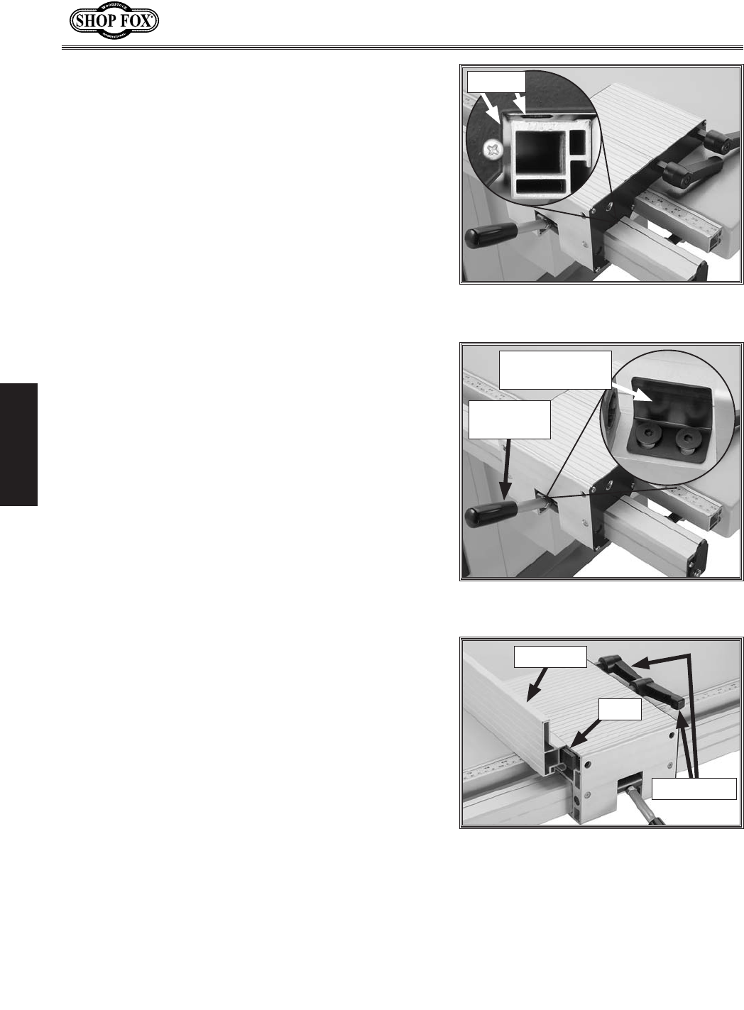
(,% Place a 12mm flat washer on the crosscut table
lock lever, then insert it through the crosscut
fence and thread the M12-1.75 T-nut onto the end
approximately two turns.
(-% Align the T-nuts on the crosscut table with the
T-slot in the face of the sliding table, then slide
the crosscut table into position on the sliding table
(=`^li\))) and tighten the crosscut table lock lever.
=`^li\))% Crosscut table installation.
T-Slot
Lock Lever
(.% Place the crosscut table support leg on the extension
arm, and attach it to the crosscut table with four
M6-1 x 16 cap screws, 6mm lock washers, and 6mm
flat washers.
(/% Insert the two crosscut brace knobs with 8mm flat
washers through the crosscut table, then thread
the square nuts onto the ends of the knob threads
(=`^li\)+#8). Slide the T-slot in the support bar
over both T-nuts, and tighten the knobs (=`^li\)+#
9).
Jlggfik
9Xi
BefY
D/$(%),o,'
JhlXi\Elk
D/$(%),
:ifjjZlk
KXYc\
=cXkNXj_\i
/dd
9
8
=`^li\)+% Installing support bar on
crosscut table.
T-Nut
-22-
N(/((('Jc`[`e^KXYc\JXn
J<KLG
(0% Slide the pivot stud assembly and the M8-1.25 x 60
T-bolt into the crosscut fence T-slot, as shown in
=`^li\),.
)'% Align the T-bolt and pivot stud with the crosscut
table insertion points (=`^li\),), and install the
fence on the table.
)(% Thread the M8-1.25 knob with an 8mm flat washer
onto the bottom of the T-bolt from the underside of
the table.
=`^li\),% Pivot stud and T-bolt installed
in crosscut fence.
T-Bolt M8-1.25 x 60
Pivot Stud
Assembly
%%%kfK$Yfck
BefY
D/$(%),o,,
=cXkNXj_\i
/dd
))% Hold the crosscut fence against the positive stop
bolt, shown in =`^li\)-, then tighten the knob
underneath the crosscut table to lock the crosscut
fence in position.
Efk\1K_`jgfj`k`m\jkfgYfckZXeY\]`e\$kle\[cXk\i
kf\ejli\k_Xkk_\ZifjjZlk]\eZ\`jjhlXi\kfk_\
YcX[\%
=`^li\)-% Positive stop bolt against the
crosscut fence.
Positive
Stop Bolt
)*% Install the flip stops in the T-slot on the crosscut
fence, as shown in =`^li\)., and use the crosscut
fence lock knob to secure the extendable end of the
fence in position.
=`^li\).% Flip stops installed on crosscut
fence.
Flip Stops
Crosscut Fence Lock Knob
M8-1.25 x 25
-23-
N(/((('Jc`[`e^KXYc\JXn
J<KLG
),% Attach the sliding table handle, as shown in =`^li\
*', with two premounted button head screws and
flat washers.
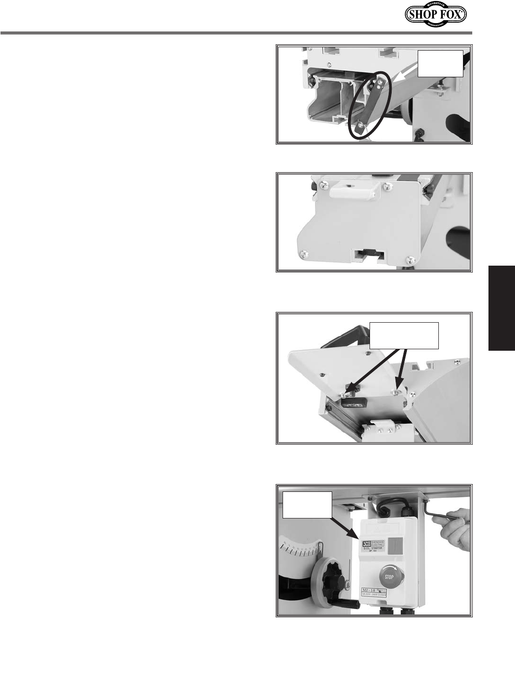
)+% Remove the shipping brace from the sliding table
(=`^li\)/), then install the sliding table end cover
over the fixed part of the sliding table end, as shown
in =`^li\)0, using the pre-mounted hardware.
=`^li\)0% Sliding table end cover
installed.
=`^li\*'% Sliding table handle attached
to end of sliding table.
Button Head
Cap Screws
)-% Thread two M5-.8 x 12 cap screws with 5mm lock
washers through the switch bracket and into the
sliding table base, and tighten the cap screws (see
=`^li\*().
=`^li\*(% Magnetic switch installed.
Magnetic
Switch
=`^li\)/% Sliding table shipping brace.
Shipping
Brace
-24-
N(/((('Jc`[`e^KXYc\JXn
J<KLG
9\]fi\gifZ\\[`e^n`k_k_\e\okjk\gj#n\
i\Zfdd\e[k_Xkpfln\Xi^cfm\jkfgifk\Zkpfli
_Xe[jn_\e_Xe[c`e^Xe[`ejkXcc`e^k_\YcX[\%
).% Thread the feet all the way into the bottom of the
support legs. DO NOT remove the hex nuts pre-
installed on the bottom of the feet, since they will
be used after the legs are installed.
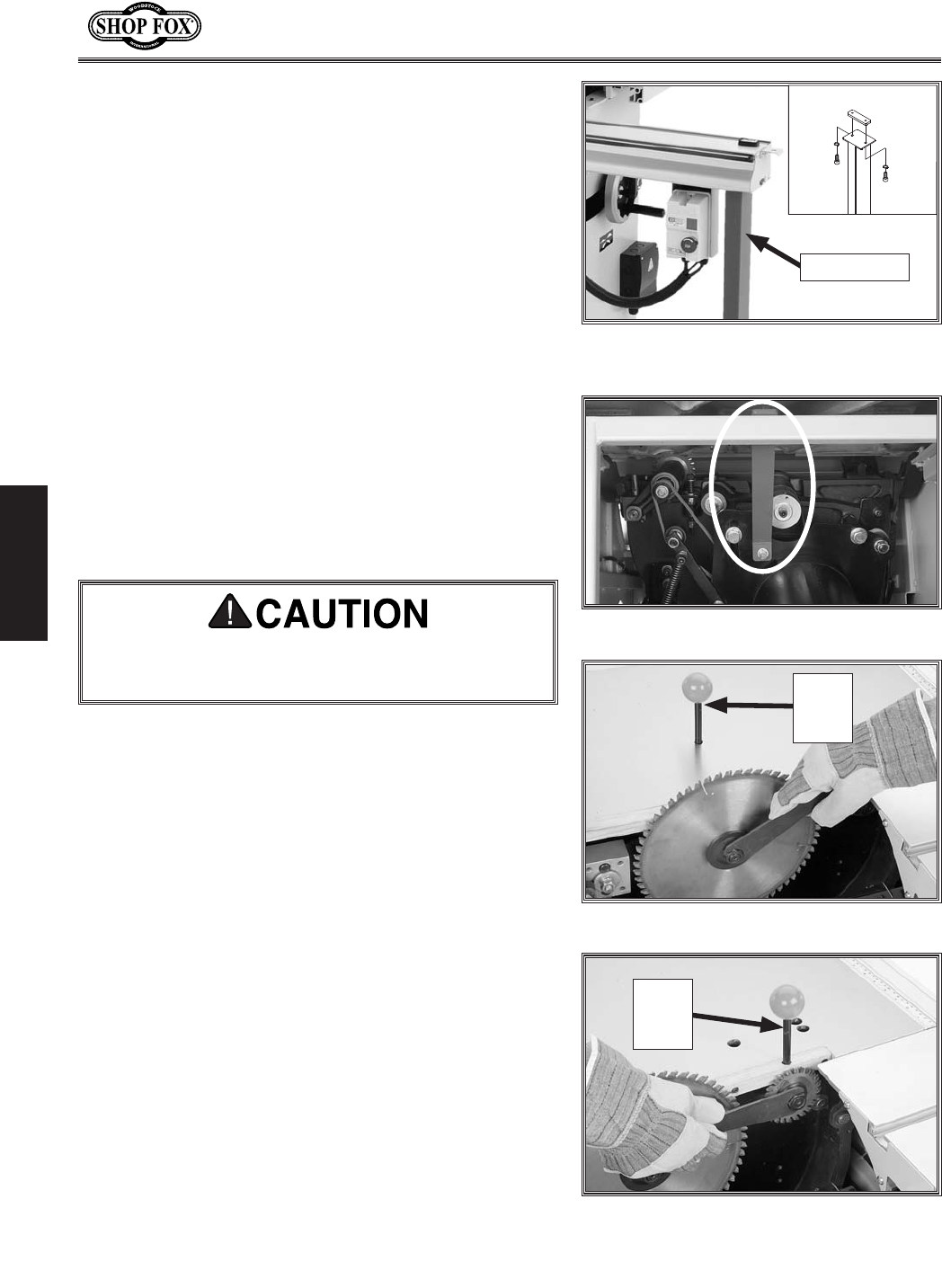
)/% Thread two M10-1.5 x 30 cap screws and 10mm lock
washers through each support leg and part way into
the T-slot plates for the legs, slide the T-slot plates
into the both ends of the sliding table base, and
tighten the mounting cap screws (see =`^li\*)).
)0% Adjust the feet downward so they press against the
floor, then tighten the hex nuts up against the sup-
port leg so the feet are locked in place.
*'% Open the cabinet door and remove the motor ship-
ping brace shown in =`^li\**.
*(% Tilt the blade assembly to 0˚, then slide the slid-
ing table forward all the way until you can open
the lower blade guard cover and access the blade
arbors.
=`^li\*)% Support leg installed (1 of 2
shown).
Support Leg
=`^li\**% Motor shipping brace.
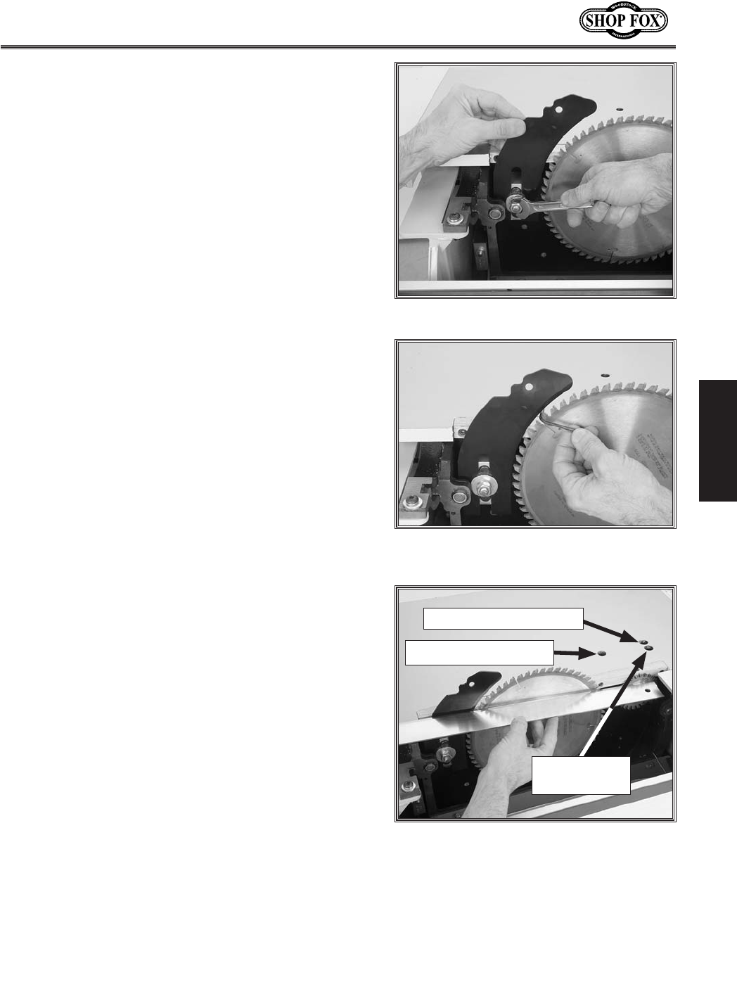
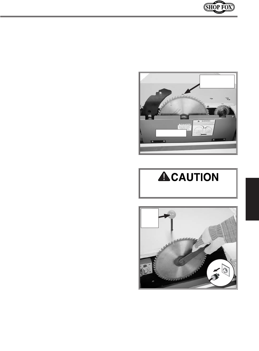
*)% Insert the arbor lock tool into the hole shown in
=`^li\*+, rotate the arbor until the arbor lock tool
seats, then install the main blade, using the included
arbor wrench to loosen and tighten the arbor nut
(the arbor nut has left-hand threads and loosens
clockwise). There MUST be an arbor flange between
the blade and the arbor nut.
=`^li\*,% Installing scoring blade.
Arbor
Lock
Tool
**% Insert the arbor lock tool into the hole shown in
=`^li\*,, rotate the arbor until the arbor lock tool
seats, then install the scoring blade, using the arbor
wrench. There MUST be an arbor flange on both
sides of the blade.
=`^li\*+% Installing main blade.
Arbor
Lock
Tool
-25-
N(/((('Jc`[`e^KXYc\JXn
J<KLG
*+% Install the riving knife as shown in =`^li\*-, but do
not tighten the mounting bolt yet.
Efk\1N_`c\k_\dflek`e^Yfck`jcffj\#k_\i`m`e^
be`]\ZXeY\X[aljk\[lgfi[fne%
=`^li\*-% Installing riving knife.
=`^li\*.% Adjusting the riving knife
spacing.
*,% Adjust the riving knife approximately 1⁄8" away from
the main blade, using a 1⁄8" or 3mm hex wrench as a
guide (=`^li\*.), and make sure the top of the riv-
ing knife is positioned below the blade's highest point
of rotation, as shown in =`^li\,) on GX^\*+.
*-% Use a straightedge to make sure the riving knife and
scoring blade are aligned with the main blade.
— The riving knife position can be modified slightly
by shimming. Refer to GX^\*, for more details.
— The scoring blade alignment can be changed by
adjusting the set screws accessible through the
table top (see =`^li\*/or refer to GX^\*.).
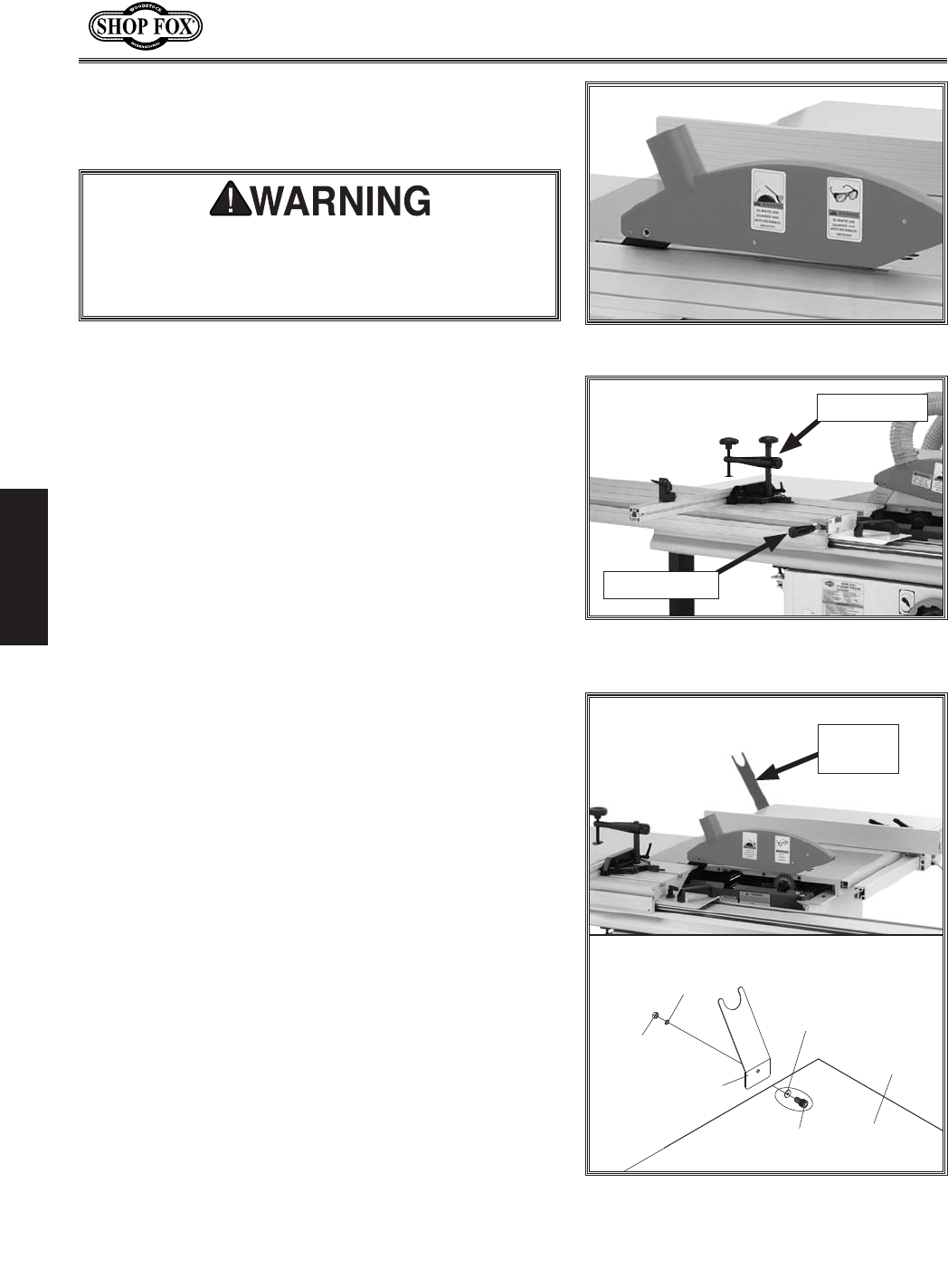
=`^li\*/% Access holes for scoring blade
adjustment controls.
Scoring Controls Lock
Scoring Blade Elevation
Scoring Blade
Alignment
-26-
N(/((('Jc`[`e^KXYc\JXn
J<KLG
*.% Install the blade guard on the riving knife, as shown
in =`^li\*0, with the M8-1.25 x 40 button head cap
screw shipped in the blade guard.
=`^li\+'% Push handle and miter gauge
installed.
Miter Gauge
Push Handle
*/% Assemble the miter gauge and push handle, as shown
in =`^li\+'.
=`^li\*0% Blade guard installed.
*0% Install the hose support, as shown in =`^li\+(, with
hardware shown below.
=`^li\+(% Hose support installed.
Hose
Support
?fj\
Jlggfik
CfZbNXj_\i
('dd =cXkNXj_\i
('dd CXi^\
<ok\ej`fe
KXYc\
:XgJZi\n
D('$(%,o),
?\oElk
D('$(%,
K_\YcX[\^lXi[&[ljk_ff[DLJKY\`ejkXcc\[kf
i\[lZ\k_\i`jbf]`ealip]ifdXZZ`[\ekXcYcX[\
ZfekXZk#b`ZbYXZb#fi]cp`e^[\Yi`j%K_`j`jefkXe
fgk`feXcjk\g%
-27-
N(/((('Jc`[`e^KXYc\JXn
J<KLG
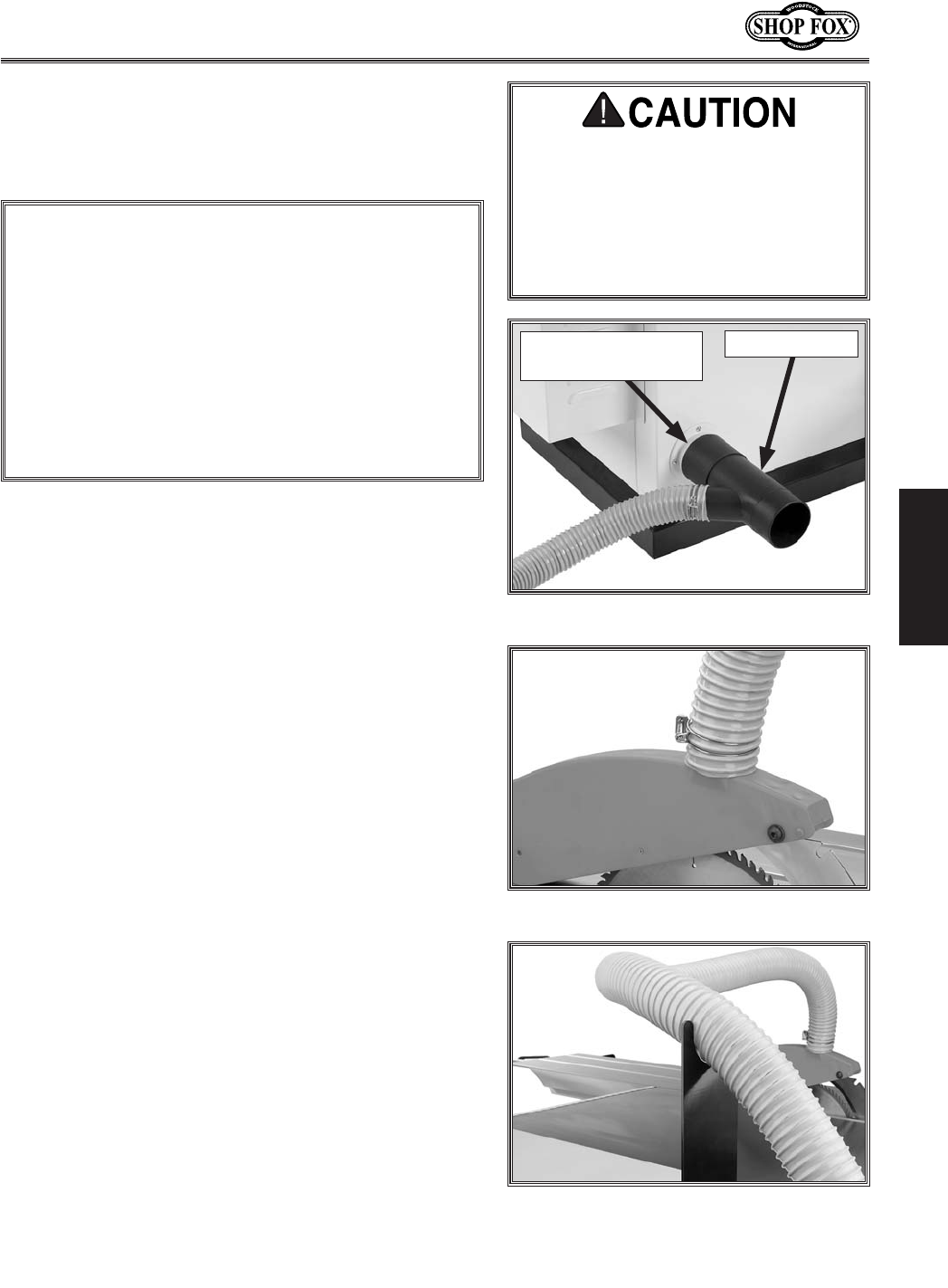
Figure +). 4" dust port connected.
*% Run the 2½" hose over the hose support, as shown in
=`^li\++.
Figure +*. 2½" Dust port connected.
=`^li\++% Dust hose support in use.
(% Secure a 4" dust hose to the dust port located under
the saw table (=`^li\+)).
Efk\1=fi]XjkXe[\XjpZfee\Zk`fekfX[ljkZfcc\Z$
k`fejpjk\d#n\i\Zfdd\e[lj`e^k_\Df[\cN('*/
+Hl`Zb;`jZfee\Zk]`kk`e^n`k_k_\Df[\c;*00-+
o)
(Ð)P$]`kk`e^#Xjj_fne`e=`^li\+)%
)% Attach a 2½" dust hose to the blade guard dust port,
as shown in =`^li\+*.
;FEFKfg\iXk\k_`jdXZ_`e\n`k_$
flk Xe X[\hlXk\ [ljk Zfcc\Zk`fe jpj$
k\d% K_`j dXZ_`e\ Zi\Xk\j jlYjkXek`Xc
Xdflekjf]nff[[ljkn_`c\fg\iXk`e^%
=X`cli\kflj\X[ljkZfcc\Zk`fejpjk\d
ZXei\jlck`ej_fikXe[cfe^$k\idi\jg`$
iXkfip`cce\jj%
I\Zfdd\e[\[:=DXk+;ljkGfik1%%%%%%%%%%%%% +'':=D
I\Zfdd\e[\[:=DXk)(&);ljkGfik1%%%%%%%%%% (,':=D
;ljk:fcc\Zk`fe
EFK@:<
;fefkZfe]lj\k_`j:=Di\Zfdd\e[Xk`fen`k_k_\
iXk`e^f]k_\[ljkZfcc\Zkfi%Kf[\k\id`e\k_\:=DXk
k_\[ljkgfik#pfldljkZfej`[\ik_\j\mXi`XYc\j1(
:=DiXk`e^f]k_\[ljkZfcc\Zkfi#) _fj\kpg\Xe[
c\e^k_Y\kn\\ek_\[ljkZfcc\ZkfiXe[k_\dXZ_`e\#*
eldY\if]YiXeZ_\jfinp\j#Xe[+ Xdflekf]fk_\i
fg\ec`e\jk_ifl^_flkk_\jpjk\d%<ogcX`e`e^_fnkf
ZXcZlcXk\k_\j\mXi`XYc\j`jY\pfe[k_\jZfg\f]k_`j
dXelXc%:fejlckXe\og\ikfigliZ_Xj\X^ff[[ljk
Zfcc\Zk`fe_fn$kfYffb%
D3996 Y-Fitting
W1038
4" Quick Disconnect
-28-
N(/((('Jc`[`e^KXYc\JXn
J<KLG
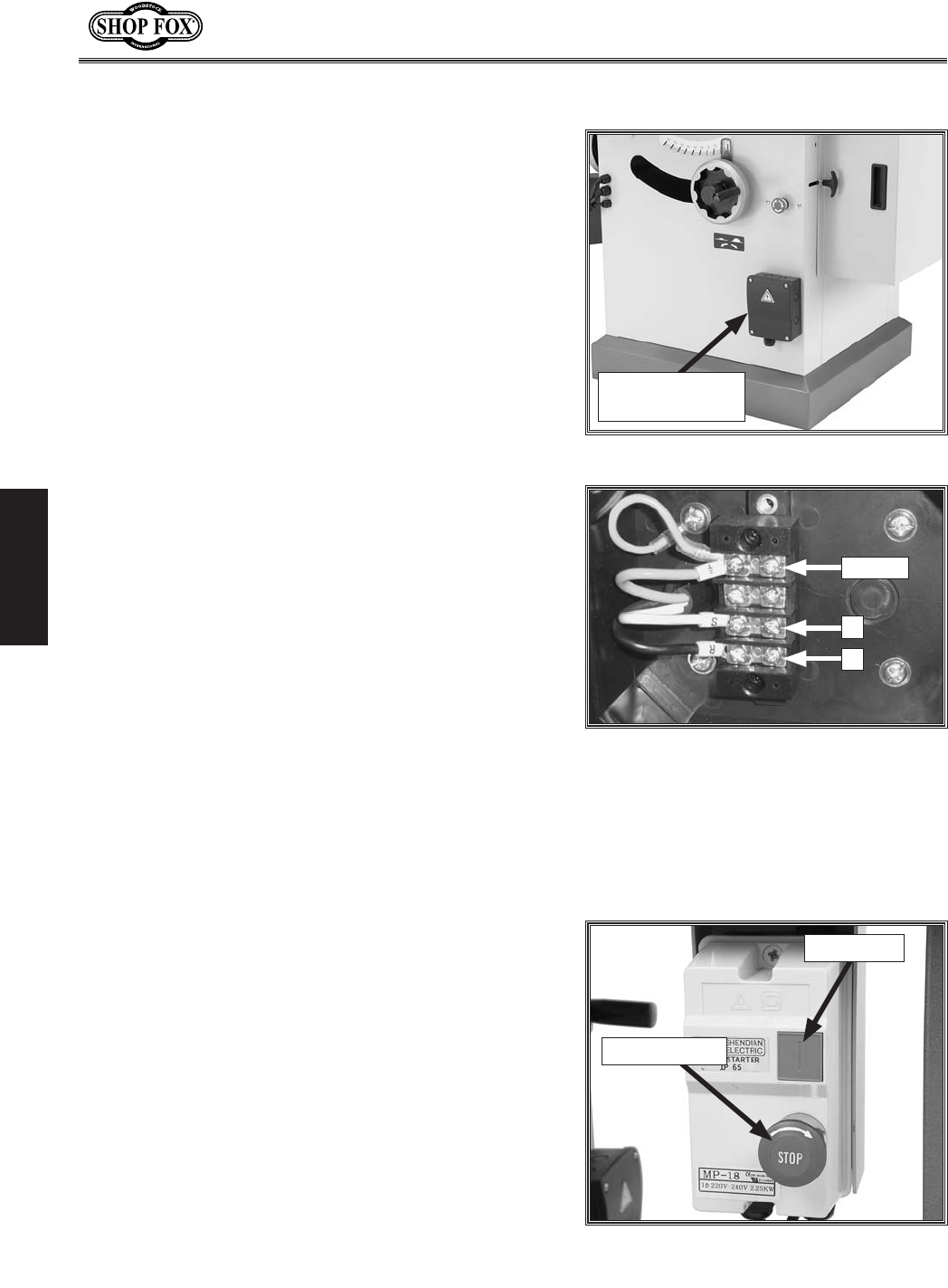
=`^li\+,% Power connection box.
Power
Connection Box
Figure +-. Power connection terminals.
R
Ground
S
Before connecting the saw to power, read through
<c\Zki`ZXc section on GX^\() to verify that your setup
follows the safety and circuit requirements for this
machine.
Open the power connection box shown in =`^li\+,.
Gfn\i:fee\Zk`fe
Connect the power wires to the terminals shown in =`^li\
+-, tighten the strain relief so the wires can't be pulled
from the terminals, then close the power connection box.
=`^li\+.% Main power controls.
ON Button
STOP Button
K\jk Ile
Once the assembly is complete and the power source is
connected, test run your machine to make sure it runs
properly and is ready for regular operation.
The test run consists of verifying the following: 1) The
motor powers up and runs correctly, 2) the stop button
safety feature works correctly, and 3) the safety limit
switches work correctly.
If, during the test run, you cannot easily locate the source
of an unusual noise or vibration, immediately stop using
the machine, then review KiflYc\j_ffk`e^ on GX^\-).
If you still cannot remedy a problem, contact our Tech
Support at (360) 734-3482 for assistance.
Before beginning the test run, review the power controls
shown in =`^li\+. and :fekifcj=\Xkli\j on GX^\*.
-29-
N(/((('Jc`[`e^KXYc\JXn
J<KLG
Kfk\jkilek_\jXn#[fk_\j\jk\gj1
(% Put on safety glasses, make sure any bystanders are
out of the way, and that all tools have been removed
from the saw.
)% Push in, then rotate both STOP buttons clockwise
until they pop out. This resets the switch so the
machine can be started.
*% Press the ON button. The blades should startup and
run smoothly without any problems. @]XepgifYc\dj
fZZli#`dd\[`Xk\cpgi\jjk_\JKFGYlkkfe%
+% Press the STOP button, then press the ON button.
— The saw should NOT start if the disabling feature
on the STOP button is working correctly. If this is
true, continue to Jk\g-.
— If the saw DOES start when the STOP button is
pushed in, then the safety feature on the STOP
button is not working correctly. Call Tech Support
for advice before proceeding any further with the
test run or machine operations.
,% DISCONNECT SAW FROM POWER!
-% Move the sliding table all the way forward, then
open the lower blade guard (refer to GX^\*- for
details on accessing and opening the blade guard).
Opening the lower blade guard triggers the limit
switch.
.% Connect the saw to the power source and rotate the
STOP button clockwise so it pops out.
/% (During this step, be prepared to immediately press
the STOP button if the blades start operating.) Press
the ON button.
— If the blade guard limit switch functions correctly,
the machine will not start. If this is true, continue
to Jk\g0.
— If the machine starts during this test, the limit
switch is NOT functioning correctly. Disconnect the
saw from power, and call Tech Support for advice
before proceeding any further with the test run or
machine operations.
0% Close the lower blade guard and move the sliding
table back to the center of the machine.
@]k_\jXn[f\jefkfg\iXk\XjjkXk\[`e
k_`jj\Zk`fe#i\m`\nKiflYc\j_ffk`e^fe
GX^\-)%@]pfle\\[X[[`k`feXc_\cg#ZXcc
K\Z_JlggfikXk*-' .*+$*+/)%;FEFK
gcXZ\XdXZ_`e\`ekfi\^lcXifg\iXk`fe
`]pfljljg\Zkk_Xk`k`jdXc]leZk`fe`e^#
fij\i`flj`ealipZflc[fZZli%
-30-
N(/((('Jc`[`e^KXYc\JXn
FG<I8K@FEJ
FG<I8K@FEJ
>\e\iXc
This machine will perform many types of operations
that are beyond the scope of this manual. Many of these
operations can be dangerous or deadly if performed
incorrectly.
The instructions in this section are written with the
understanding that the operator has the necessary
knowledge and skills to operate this machine. If at any
time you are experiencing difficulties performing any
operation, stop using the machine!
If you are an inexperienced operator, we strongly
recommend that you read books, industry magazines,
or seek training from an experienced Jc`[`e^KXYc\JXn
operator before performing any unfamiliar operations.
Above all, your safety should come first!
8cnXpjn\XijX]\kp^cXjj\jn_\efg\i$
Xk`e^k_`jdXZ_`e\%=X`cli\kfZfdgcp
dXpi\jlck`ej\i`fljg\ijfeXc`ealip%
I<8;Xe[le[\ijkXe[k_`j\ek`i\`ejkilZ$
k`fe dXelXc Y\]fi\ lj`e^ k_`j dXZ_`e\%
J\i`flj g\ijfeXc `ealip dXp fZZli `]
jX]\kpXe[fg\iXk`feXc`e]fidXk`fe`jefk
le[\ijkff[ Xe[ ]fccfn\[% ;F EFK i`jb
pflijX]\kpYpefki\X[`e^
;FEFK`em\jk`^Xk\gifYc\djfiX[aljk
k_\dXZ_`e\ n_`c\ `k`jilee`e^% NX`k
lek`c k_\ dXZ_`e\ `j klie\[ F==#
legcl^^\[ Xe[ Xcc nfib`e^ gXikj
_Xm\Zfd\kfXZfdgc\k\jkfgY\]fi\
gifZ\\[`e^
JX]\kp?XY`kj
Your safety is important. Always think about safety
when operating this machine. The operator is ultimately
responsible for their own safety, as well as the safety
of bystanders. Every cutting operation is different and
may require safety equipment or safety procedures not
mentioned in this manual. Use common sense!
=fccfnk_\j\jX]\kpk`gj<M<IPk`d\pfllj\pflijXn1
• Stand to the left of the blade line-of-cut when
performing a cutting operation.
• Turn the saw F== and allow the blade to come to a
complete stop before removing the cut-off piece.
• Make sure that the riving knife is always aligned with
the main blade before cutting!
• Always make sure the blade guard is installed and
works correctly.
• Carefully plan each cutting operation to avoid
injuries.
• When you release the sliding table lock, make sure
that the knob is positioned so that it will not lock
the table during a cut.

-31-
N(/((('Jc`[`e^KXYc\JXn
FG<I8K@FEJ
Nfibg`\Z\@ejg\Zk`fe
Some workpieces are not safe to cut or may require
modification before they can be cut.
9\]fi\Zlkk`e^#^\k`ek_\_XY`kf]`ejg\Zk`e^Xcc
nfibg`\Z\j]fik_\]fccfn`e^_XqXi[j1
• =fi\`^eFYa\Zkj1 Nails, staples, dirt, rocks and other
foreign objects are often embedded in wood. While
cutting, these objects can become dislodged and hit
the operator, they can cause kickback, and they can
break or chip the blade, which might then fly apart.
Always visually inspect your workpiece for these
items. If they can't be removed, DO NOT cut the
workpiece.
CXi^\&Cffj\Befkj1Loose knots can become dis-
lodged during the cutting operation. Large knots
can cause kickback and machine damage. Choose
workpieces that do not have large/loose knots or
plan ahead to avoid cutting through them.
N\kfi>i\\eJkfZb1 Cutting wood with a moisture
content over 20% causes unnecessary wear on the
blades, increases the risk of kickback, and yields
poor results.
• <oZ\jj`m\NXig`e^1 Workpieces with excessive
cupping, bowing, or twisting are dangerous to cut
because they are unstable and often unpredictable
when being cut. DO NOT use workpieces with these
characteristics!
• D`efiNXig`e^1 Workpieces with slight cupping can
be safely supported if the cupped side is facing the
table or the fence. On the contrary, a workpiece
supported on the bowed side will rock during a cut
and could cause kickback or severe injury.
• @dgifg\iDXk\i`Xc1 This machine is intended for
cutting natural and man-made wood products, lami-
nate covered wood products, and some plastics. This
machine is NOT designed to cut metal, glass, stone,
tile, etc.; cutting these materials with a table saw
may lead to injury. Cutting drywall or cementitious
backer board creates extremely fine dust and may
reduce the life of the bearings—we do NOT recom-
mend cutting these products with this saw.
-32-
N(/((('Jc`[`e^KXYc\JXn
FG<I8K@FEJ
Efe$K_ifl^_K_ifl^_
:lkj
Efe$K_ifl^_:lkj
A non-through cut is a sawing operation where the blade
does not protrude above the top face of the wood stock,
as shown in Figure +/.
Examples of non-through cuts include dadoes and
rabbets. Non-through cuts have a higher risk of injury
from kickback because the splitter and blade guard
must be removed. When making non-through cuts with a
standard blade, the riving knife MUST be installed. When
making non-through cuts with a dado blade, extreme
care, including using multiple light passes must be used,
because neither the blade guard or riving knife can be
used.
JX]\kpgi\ZXlk`fejXe[`ejkilZk`fej]fi\XZ_kpg\f]Zlk
Xi\cfZXk\[fek_\]fccfn`e^gX^\j1
;X[f:lkj1GX^\+,
IXYY\k:lkj1GX^\+.
I\jXn`e^:lkj1GX^\+0
K_ifl^_:lkj
A through cut is a sawing operation in which the
workpiece is completely sawn through, as shown in Figure
+0. Examples of through cuts are rip cuts, cross cuts,
miter cuts, and beveled cuts. The blade guard assembly
MUST be used when performing through cuts.
Read, understand, and follow instructions and safety
precautions for each type of cut to reduce the risk of
injury.
JX]\kpgi\ZXlk`fejXe[`ejkilZk`fej]fi\XZ_kpg\f]Zlk
Xi\cfZXk\[fek_\]fccfn`e^gX^\j1
I`g:lkj1GX^\+'
:ifjjZlkj1GX^\+)
D`k\i:lkj1GX^\++
=\eZ\
JXn9cX[\
Nfibg`\Z\
=`^li\+0% Example of a through cut
(blade guard not shown for illustrative
clarity).
=\eZ\
JXn9cX[\
Nfibg`\Z\
=`^li\+/% Example of a non-through cut.
-33-
N(/((('Jc`[`e^KXYc\JXn
FG<I8K@FEJ
N\Xi^cfm\jkfgifk\Zkpfli_Xe[j
n_\e_Xe[c`e^Xe[`ejkXcc`e^YcX[\j%
This saw performs best with high-quality sharp blades.
Whenever the blades become dull, replace or sharpen
them.
To change the main blade, do these steps:
(% DISCONNECT SAW FROM POWER!
)% Move the blade tilt to 0° (blade 90° to table) and
raise the main blade as far as it will go.
*% Move the sliding table all the way forward to expose
the internal blade guard that covers the blades and
riving knife, as shown in =`^li\,-.
+% Pull the blade guard away from the blades to expose
the mounting assembly. (The internal blade guard is
held in place with a magnet.)
,% Insert the arbor lock tool into the hole shown in
=`^li\,-, then rotate the blade by hand until the
arbor lock tool seats.
-% Use the arbor wrenches to remove the arbor nut and
arbor flange, then pull the old blade off the arbor.
Efk\1K_\XiYfielk_Xjc\]k_Xe[k_i\X[jXe[cffj$
\ejYpklie`e^ZcfZbn`j\%
.% Slide the new blade over the arbor with the teeth
facing the right of the saw, as shown in =`^li\,..
/% Re-install the arbor flange and the arbor nut, then
tighten them against the blade as shown in =`^li\
,.. There MUST be an arbor flange between the
blade and the arbor nut.
— If you changed the diameter of the blade during
this procedure, adjust the riving knife according to
the instructions titled I`m`e^Be`]\8[aljkd\ek on
GX^\*,.
0% Move the lower blade guard back into its original
position, next to the blades, and center the sliding
table.
=`^li\,.% Replacing the main blade.
Arbor
Lock
Tool
=`^li\,-% Internal blade guard exposed.
Blade Guard
Hole for Arbor
Lock Tool
DX`e9cX[\@ejkXccXk`fe

-34-
N(/((('Jc`[`e^KXYc\JXn
FG<I8K@FEJ
9cX[\>lXi[
The "blade guard" =`^li\,' is mounted to the riving
knife and is designed to lift as the workpiece is pushed
into the blade and remain in contact with the workpiece
throughout the entire cut.
The guard reduces injury risk by providing a barrier
around the blade that prevents accidental contact and
contains flying wood chips.
To ensure that the guard does its job effectively, the
guard must always be in the downward position while
cutting, and the hinge mechanism must be maintained in
good working condition so the guard can freely pivot up
and down.
N_\ekfLj\k_\9cX[\>lXi[
The blade guard assembly MUST always be installed on
the saw for all normal through cuts (those where the
blade cuts all the way through the thickness of the
workpiece).
When Not to Use the Blade Guard
The blade guard cannot be used on any non-through
cuts (those in which the blade does not cut all the way
through the thickness of the workpiece).
Sometimes the blade guard or its components can get in
the way when cutting very narrow workpieces or other
specialized cuts. Because the blade guard is provided
to decrease your risk of injury, it should not be used
if it gets in the way of making a safe cut. Use good
judgement!
@DGFIK8EK1 Whenever the blade guard cannot be used,
the riving knife must remain installed.
=`^li\,'% Blade guard assembly.
9cX[\>lXi[Jn`m\cj
LgXe[;fne
-35-
N(/((('Jc`[`e^KXYc\JXn
FG<I8K@FEJ
I`m`e^Be`]\
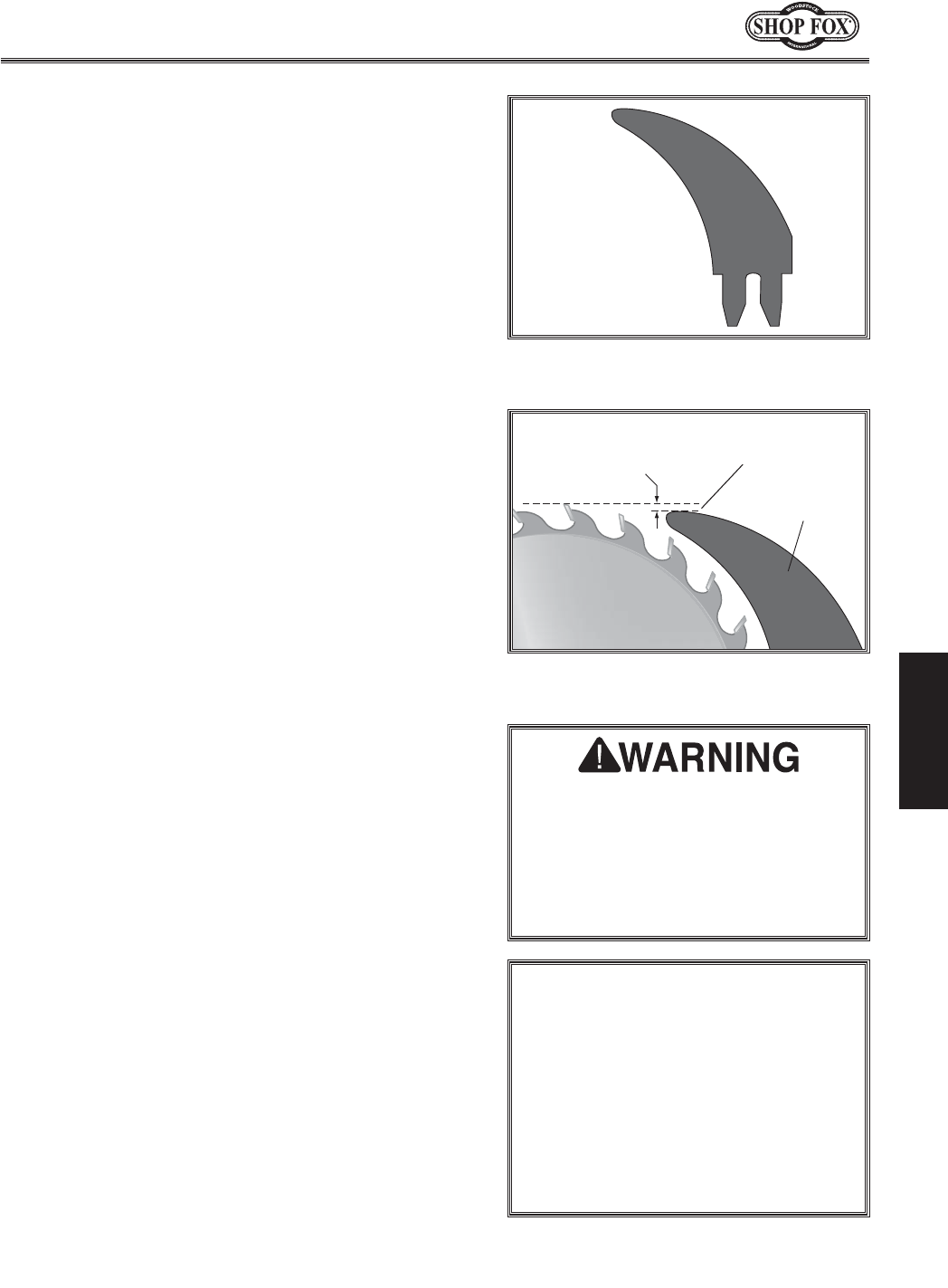
=`^li\,(% Illustration of a typical riving
knife.
I`m`e^Be`]\
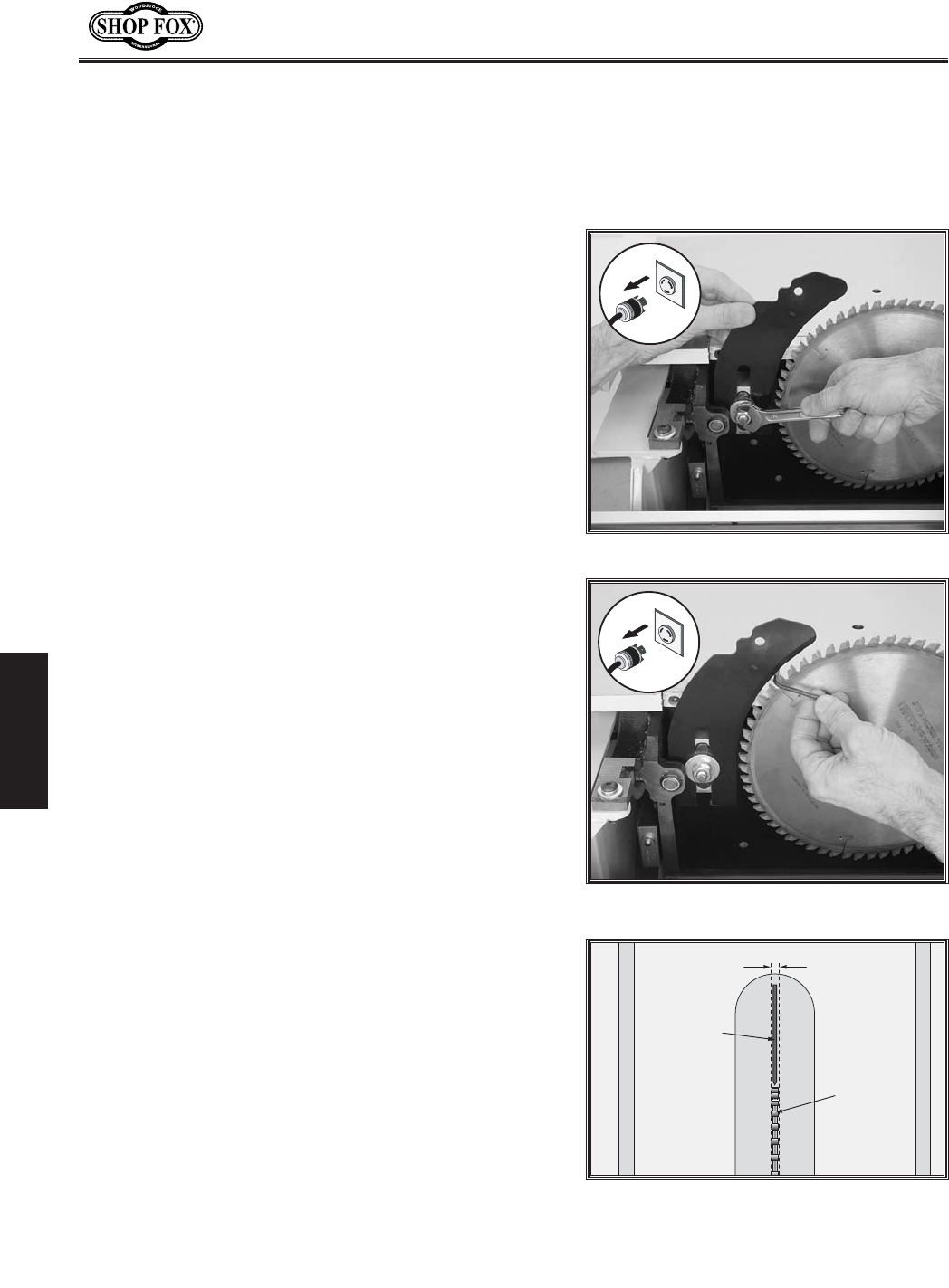
=`^li\,)% Height difference between
riving knife and blade.
G^k^c\@c^[Z
=Z^\]i9^[[ZgZcXZ
B^c^bjb&bb
BVm^bjb*bb
The riving knife (=`^li\,() is a metal plate that prevents
the newly cut workpiece from pinching the backside of
the blade and causing kickback.
When properly mounted, the riving knife is positioned
below the blade's highest point of rotation, as shown in
=`^li\,).
The height difference between the riving knife and the
blade allows the workpiece to pass over the blade during
non-through cuts (those in which the blade does not cut
all the way through the thickness of the workpiece).
The riving knife also acts as a barrier behind the blade to
reduce the risk of hands being pulled into the blade if a
kickback occurs.
The riving knife on this machine also acts as the mounting
mechanism for the blade guard.
@efi[\ikfnfibgifg\icp#k_\i`m`e^
be`]\ZXeefkY\Y\ekfid`jXc`^e\[
n`k_k_\YcX[\%@]k_\i`m`e^be`]\^\kj
XZZ`[\ekXccpY\ek#kXb\k_\k`d\kf
jkiX`^_k\e`kfialjki\gcXZ\`k%Lj`e^
XY\ekfid`jXc`^e\[i`m`e^be`]\n`cc
`eZi\Xj\k_\i`jbf]b`ZbYXZb
EFK@:<
Jfd\k_`e$b\i]YcX[\jdXpY\k_`ee\i
k_Xek_\k_`Zbe\jjf]k_\i`m`e^be`]\%
;FEFK`ejkXcck_\j\YcX[\jfek_\
jXn#Y\ZXlj\k_\nfibg`\Z\n`cc_`k
k_\i`m`e^be`]\[li`e^fg\iXk`fe#
gfjj`YcpZXlj`e^b`ZbYXZb%8cnXpj
dXb\jli\k_\b\i]f]XYcX[\pfl
`ejkXcc`jefkk_`ee\ik_Xek_\i`m`e^
be`]\%
N_\ekfLj\k_\I`m`e^Be`]\Yp@kj\c]
n`k_flk9cX[\>lXi[8kkXZ_\[
Use the riving knife by itself for all non-through cuts
made with a standard table saw blade (i.e., dadoes or
rabbet cuts in which a dado blade is NOT used, and when
using a tenoning jig).
Also, use the riving knife by itself for those special
operations where the blade guard or its components get
in the way of safe operation, such as with very narrow
cuts.
N_\eEfkkfLj\k_\I`m`e^Be`]\
The riving knife CANNOT be used with a dado blade.
Otherwise, the riving knife height will exceed the blade
height and the workpiece will hit the riving knife during
the cut, forcing the operator into a dangerous situation
of trying to turn the saw off with the workpiece stuck
halfway through the cut.
In addition, although it is possible to use the riving
knife by itself for through cutting operations, the blade
guard assembly offers far more injury protection and
risk reduction than the riving knife alone. Therefore, n\
jkife^cpi\Zfdd\e[ that you ALWAYS use the blade
guard assembly with the riving knife for all through cuts.
-36-
N(/((('Jc`[`e^KXYc\JXn
FG<I8K@FEJ
I`m`e^Be`]\8[aljkd\ek
The riving knife must be adjusted to 3mm away from the
main saw blade.
KfX[aljkk_\i`m`e^be`]\#[fk_\j\jk\gj1
(% DISCONNECT SAW FROM POWER!
)% Move the blade tilt to 0˚ (blade 90˚ to table), and
raise the main blade as far as it will go.
*% Move the sliding table all the way forward to expose
the internal blade guard that covers the blades and
riving knife.
+% Pull the internal blade guard away from the riving
knife to expose the mounting assembly. (The internal
blade guard is held in place with a magnet.)
,% Remove the upper blade guard.
-% Loosen the riving knife center bolt as shown in
=`^li\,*.
.% Position the riving knife about 3mm or 1⁄8" away
from the nearest saw tooth on the main blade, and
make sure the top of the riving knife is positioned
below the blade's highest point of rotation, as shown
in =`^li\,).
Efk\1=fiXhl`Zb^Xl^\#lj\k_\*ddfi(Ð/_\o
ni\eZ_kf]`e[k_\Zfii\ZkjgXZ`e^Y\kn\\ek_\
YcX[\Xe[k_\i`m`e^be`]\#Xjj_fne`e=`^li\,+%
/% Tighten the center bolt to secure the riving knife in
position.
0% Use a straightedge to check the riving knife align-
ment with the blade. The riving knife should be
directly behind the blade in the "Alignment Zone"
area shown in =`^li\,,.
— If the riving knife is not aligned, it must be bent
into alignment by hand or adjusted at the mount-
ing block, by shimming it out with shim stock or
electrical washers.
('% Re-install the upper blade guard, close the lower
blade guard, and move the sliding table back to cen-
ter.
=`^li\,*% Adjusting the riving knife.
=`^li\,+% Positioning the riving knife.
8c`^ed\ek
Qfe\
Jgc`kk\ifi
I`m`e^Be`]\
9cX[\
=`^li\,,% Riving knife alignment with
blade.
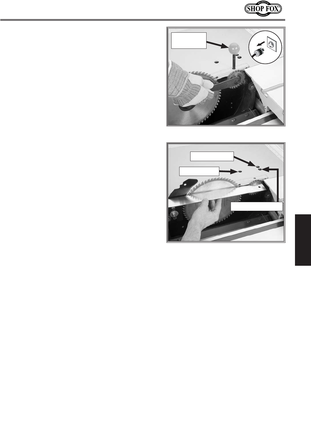
-37-
N(/((('Jc`[`e^KXYc\JXn
FG<I8K@FEJ
JZfi`e^9cX[\@ejkXccXk`fe
8[aljkd\ek
The scoring blade included with the sliding table saw has
wedge shaped teeth. The kerf thickness is adjusted by
changing the height of the scoring blade.
To change the scoring blade, do these steps:
(% DISCONNECT SAW FROM POWER!
)% Move the blade tilt to 0˚ (blade 90˚ to table), and
raise the scoring blade all the way up.
*% Move the sliding table all the way forward and pull
the internal blade guard open. (The internal blade
guard is held in place with a magnet.)
+% Remove the upper blade guard.
,% To remove the scoring blade, insert the arbor lock
tool in the table (=`^li\,/), rotate the scoring
blade to seat the arbor lock tool, and use the arbor
wrenches to remove the arbor nut and arbor flange.
Efk\1K_\XiYfielk_Xji`^_k$_Xe[k_i\X[jXe[
cffj\ejYpklie`e^Zflek\iZcfZbn`j\%
-% Install the new scoring blade, re-install the arbor
flange and the arbor nut, and tighten them against
the blade set. There MUST be an arbor flange
between the blade and the arbor nut.
.% Unlock the scoring blade controls by inserting a 6mm hex wrench into the controls lock hole shown
in =`^li\,0 and turning the mechanism inside counterclockwise until loose.
/% Adjust the height of the scoring blade until the exposed portion equals the kerf thickness of the
main blade. The scoring blade height control is accessed through the hole in the table (=`^li\
,0)and adjusts with a 6mm hex wrench. Use a straightedge to verify that the scoring blade kerf
matches the main blade.
0% If the scoring blade is not aligned with the main blade, adjust the blade alignment control (=`^li\
,0), using a straightedge as a guide.
('% Tighten the controls lock.
((% Move the lower blade guard back into its original position, and center the sliding table.
()% Perform a test cut and check for chip out on the underside of the test piece. If there is chip out,
make the adjustments necessary to match the kerfs.
=`^li\,/%Removing the scoring blade.
Arbor Lock
Tool
=`^li\,0% Checking and adjusting scoring
blade positioning.
Controls Lock
Height Control
Alignment Control
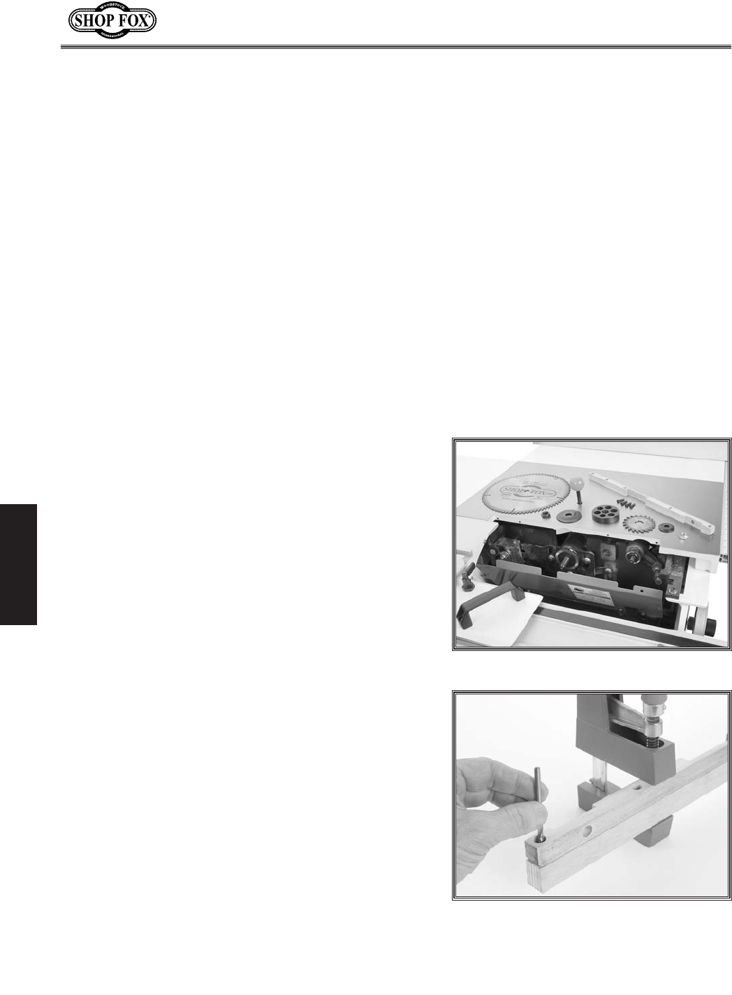
-38-
N(/((('Jc`[`e^KXYc\JXn
FG<I8K@FEJ
;X[f9cX[\@ejkXccXk`fe
This saw can only accept a dado blade with 5⁄8" arbor
hole and a maximum diameter of 8". The maximum width
of dado blade that can be installed is 13⁄16". Attempting
to install a dado blade that is sized larger than these
maximum sizes is dangerous and should be avoided. If you
have any doubts or questions about the size of dado blade
you want to install, call our Technical Support before
proceeding.
In order to install a dado blade, the scoring blade must
be removed and a zero-clearance table insert must be
made specifically for the dado blade you will install. If
you plan on making dadoes at varying widths, we strongly
recommend making a zero-clearance table insert for each
thickness of dado blade that will be used.
A zero clearance insert can be made for the saw in less
than 30 minutes, and can be made of 3⁄4" furniture quality
plywood or a hardwood.
@k\djE\\[\[ Hkp
Table Saw ........................................................1
Drill Press ........................................................1
Sander ............................................................1
Drill Bits 7⁄32" and 13⁄32" ................................. 1 Each
Plywood/Hardwood Piece 14" x 11⁄16" x 3⁄4" ................1
KfdXb\Xq\ifZc\XiXeZ\kXYc\`ej\ik#[fk_\j\jk\gj1
(% DISCONNECT SAW FROM POWER
)% Lower the main blade all the way down, remove the
blade guard, riving knife, and scoring blade. After
removing the scoring blade, reinstall the scoring
blade flanges and scoring arbor nut and tighten it.
*% Remove the main blade and the mounting spacer
behind it (see =`^li\-').
+% Remove the table insert that came with the saw.
,% Cut the new table insert to the exact length of the
included table insert and 1
1⁄16" wide.
-% Use the included table insert as a template, as
shown in =`^li\-(, to mark the mounting holes on
the new table insert. (Clamping the pieces together
while you do this will allow you to ensure the hole
spacing is exact.)
=`^li\-'% Existing insert removed.
=`^li\-(% Marking location for mounting
holes in new insert.
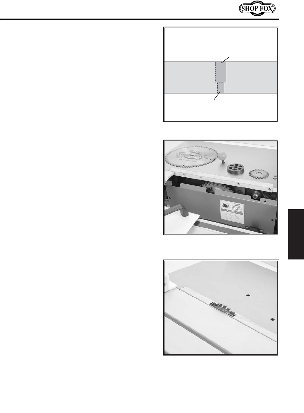
-39-
N(/((('Jc`[`e^KXYc\JXn
FG<I8K@FEJ
.% Use the
7⁄32" drill bit to drill holes completely
through the new table insert.
/% Install the
13⁄32" drill bit and use the included table
insert as a guide to set the depth stop on your drill
press to countersink the holes.
0% Countersink the holes you drilled in Jk\g. (see
=`^li\-)), so the heads of the mounting screws can
be recessed into the table insert when installed.
('% Install the dado blade at the thickness desired, mak-
ing sure the blade flange is used on the front of the
of the blade behind the arbor nut, then lower the
blade completely.
((% Test fit the new table insert in the table, then sand
the corners or trim the ends as necessary to get a
precise fit.
()% Mount the new table insert into the table and check
to make sure that it is flush with the top of the
table. If necessary, remove the insert and sand the
top of it down until it will mount up flush with the
table top (see =`^li\-*).
(*% Close the cover over the blade and move the sliding
table to the center of the saw.
(+% Connect the saw to power, start the motor, and
slowly raise the blade into the zero clearance table
insert (see =`^li\-+).
Once the blade cuts through the top of the table
insert, do not raise it higher than you anticipate
your cuts to be. Doing so will compromise some of
the zero-clearance qualities of your new table insert
once the blade is subsequently lowered.
(*Ð*)?fc\
:flek\ij`eb
]fiJZi\n?\X[
.Ð*)?fc\
]fiJZi\nK_i\X[j
Cutaway View
of Drilled Hole
New
Table Insert
=`^li\-)% Countersinking mounting holes.
=`^li\-*% New zero clearance table insert
installed.
=`^li\-+% Dado blade raised into zero-
clearance table insert.
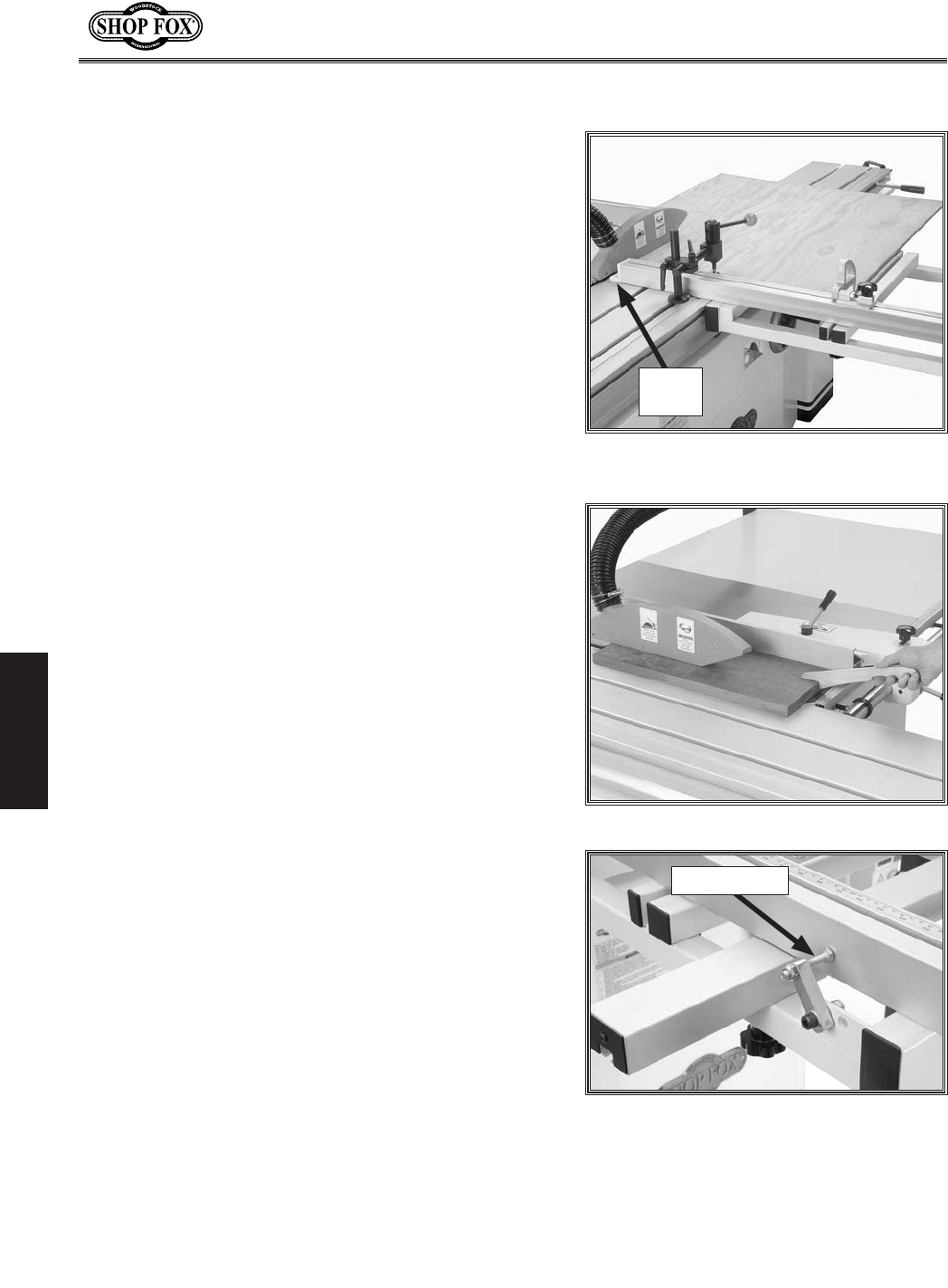
-40-
N(/((('Jc`[`e^KXYc\JXn
FG<I8K@FEJ
I`g:lkk`e^
This saw has the capability of rip cutting large panels
(=`^li\-,). The sliding table removes the burden of
sliding a large and heavy panel over a stationary table
surface.
This saw also has the capability of rip cutting smaller
boards, using the machine as a traditional table saw
(=`^li\--). Smaller, lighter boards are easier to slide
across the stationary cast iron table surface to the right
of the saw blade.
Determine which cutting operation will be best suited for
the workpiece to be ripped.
— To use the sliding table, read the instructions
titled “Rip Cutting w/Sliding Table.”
— To use the machine as a traditional table saw, skip
ahead to “Rip Cutting w/Rip Fence.”
I`g:lkk`e^n`k_Jc`[`e^KXYc\
(% Install the crosscut fence on the crosscut table, and
rotate it until the fence touches the 90° stop bolt
(=`^li\-.).
)% Check to make sure the fence is at 90˚ and, if nec-
essary, adjust it as described in :Xc`YiXk`e^:ifjjZlk
=\eZ\0'Jkfgj on GX^\,/.
*% Slide the fence so the plastic block on the end is
next to the blade teeth—this calibrates the scale to
zero—then tighten the lock knob.
Efk\18mf`[Zlkk`e^k_\gcXjk`ZYcfZbfek_\\e[f]
k_\]\eZ\%
+% Set a flip stop to the desired width-of-cut.
,% Position the blade guard to the correct height for your
workpiece.
-% Load the workpiece onto the table saw. The set up
should look similar to =`^li\-,.
.% Take all the necessary safety precautions, then per-
form the cutting operation.
Plastic
Block
=`^li\-,% Rip cutting with the sliding
table.
=`^li\--% Traditional rip cutting.
=`^li\-.% Crosscut fence mounting
locations.
90° Stop Bolt
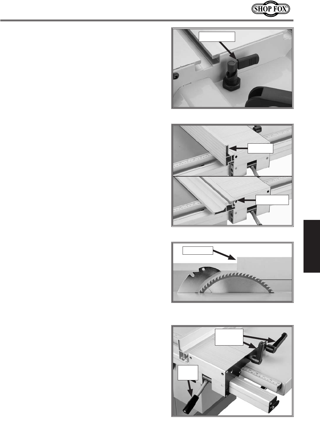
-41-
N(/((('Jc`[`e^KXYc\JXn
FG<I8K@FEJ
I`g:lkk`e^n`k_I`g=\eZ\
(% Slide the crosscut table out of the way.
)% Lock the sliding table into a stationary position (see
=`^li\-/).
Efk\1K_\kXYc\n`ccfecpcfZb`egcXZ\n_\e`k`j
Z\ek\i\[n`k_k_\jXnZXY`e\k%
+% Slide the leading end of the rip fence so it is even
with the center of the main saw blade as shown in
=`^li\.'.
Efk\1K_`jk\Z_e`hl\Xccfnjk_\]`e`j_\[Zlk$f]]
g`\Z\kfÈ]XccÉXnXp]ifdk_\YcX[\n_\ek_\Zlk$
k`e^fg\iXk`fe`jZfdgc\k\2i\[lZ`e^k_\gfjj`Y`c`kp
f]b`ZbYXZb%
*% Place the rip fence in the vertical position for larger
workpieces, or in the horizontal position for angled
cuts and for small workpieces (see =`^li\-0).
,% Tighten the lock handles (=`^li\.() to secure the
rip fence against the base.
-% Pull up the lock lever to loosen the fence base on
the rail, position the fence at the correct distance
away from the blade (as needed for the cut), then
push down the lock lever to lock the fence base in
position.
.% Take all the necessary safety precautions, then make
the cut as you would with a traditional table saw.
Figure .'. Rip fence even with center of
blade (blade guard removed for clarity).
Rip Fence
Table Lock
=`^li\-/% Sliding table lock.
=`^li\-0% Rip fence positions.
Horizontal
Vertical
Lock
Lever
=`^li\.(% Rip fence micro-adjusting controls.
Lock
Handles
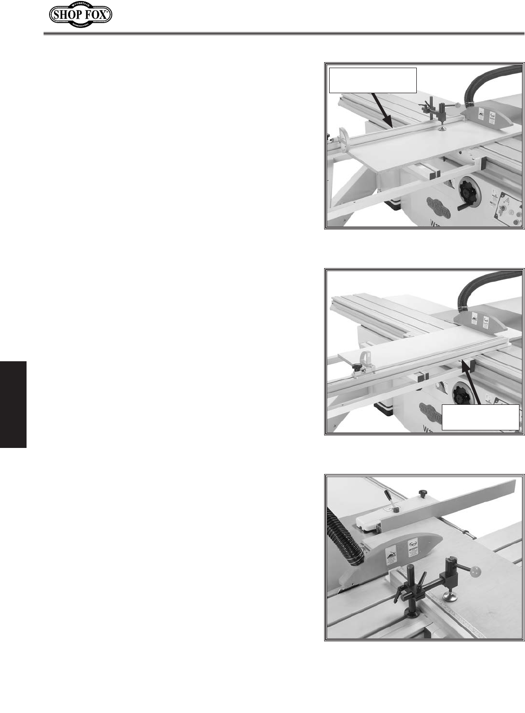
-42-
N(/((('Jc`[`e^KXYc\JXn
FG<I8K@FEJ
:ifjjZlkk`e^
This saw can crosscut full size panels with the crosscut
fence in the forward or rear position, although it is easier
to load full size panels with the crosscut fence mounted
in the forward position (see =`^li\.)).
Mounting the crosscut fence in the rear position (=`^li\
.*) gives greater stability for crosscutting smaller panels.
In addition, this machine has the capability of crosscutting
workpieces while using the rip fence as a cut-off gauge
(=`^li\ .+)—as long as the rip fence is positioned in front
of the blade (see =`^li\.').
Determine which cutting operation will be best suited for
the workpiece to be crosscut.
— If you will be crosscutting full size panels, then
skip ahead to :ifjjZlkk`e^=lccJ`q\GXe\cj.
— If you will be crosscutting smaller panels, then
skip ahead to :ifjjZlkk`e^JdXcc\iGXe\cj.
— If you will be crosscutting workpieces using the
rip fence as a cut-off gauge, then skip ahead to
:ifjjZlkk`e^Lj`e^I`g=\eZ\XjX:lk$F]]>Xl^\.
Figure .+. Crosscutting workpieces
using the rip fence as a cut-off gauge.
Figure .). Crosscut fence mounted in
forward position.
Forward Mounted
Crosscut Fence
Figure .*. Crosscut fence mounting in rear
position.
Rear Mounted
Crosscut Fence
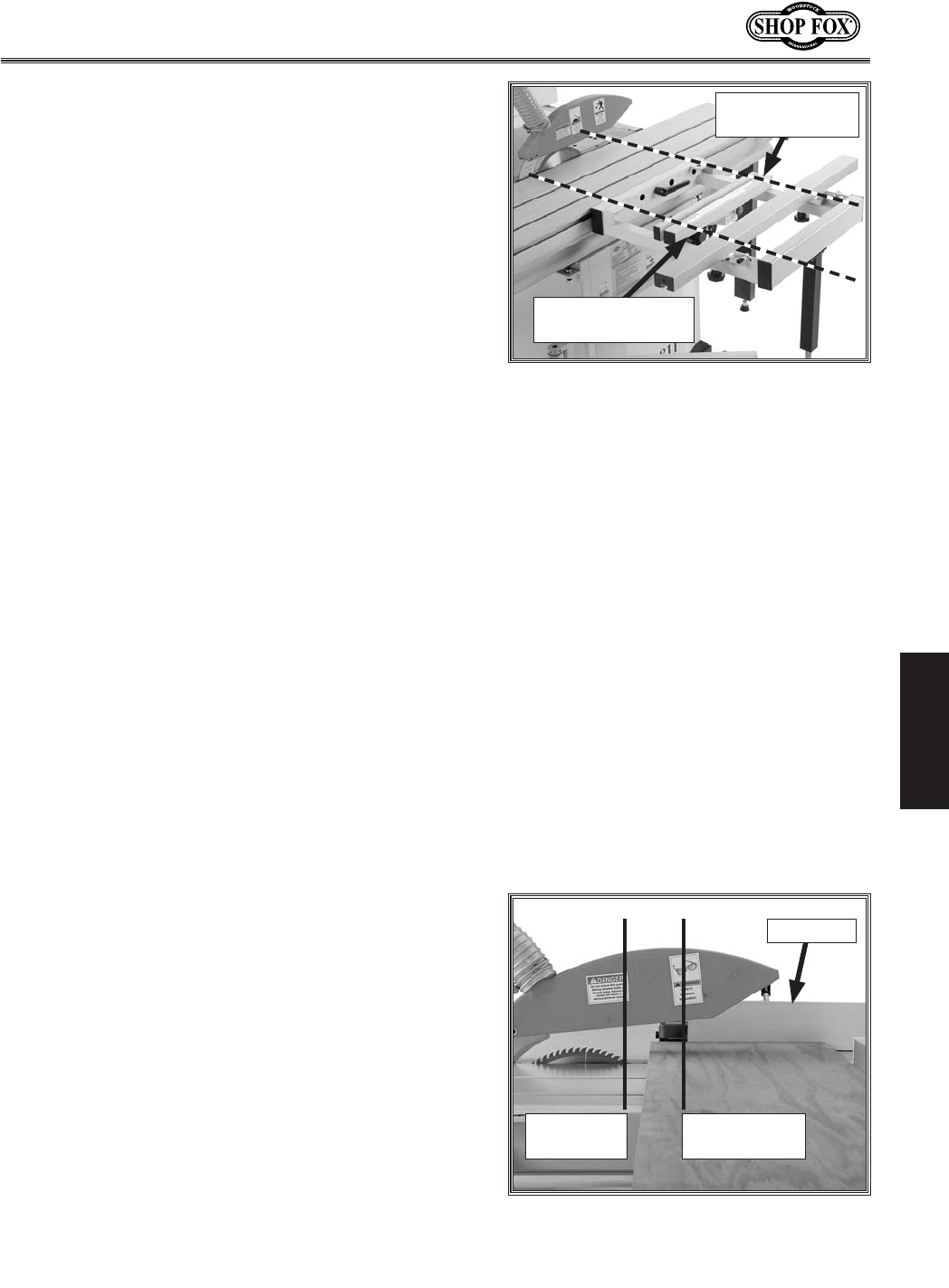
-43-
N(/((('Jc`[`e^KXYc\JXn
FG<I8K@FEJ
:ifjjZlkk`e^=lccJ`q\GXe\cj
(% Install the crosscut fence in the forward mounting
location shown in =`^li\., and lock it in place.
)% Check to make sure the fence is at 90˚. If necessary,
adjust it as described in :Xc`YiXk`e^:ifjjZlk=\eZ\
0'Jkfgj on GX^\,/.
*% Set either flip stop to the desired width-of-cut.
Extend the crosscut fence slide if the workpiece is
more than 74".
+% Load the workpiece onto the table saw (=`^li\.)).
,% Once all the necessary safety precautions have been
taken, perform the cutting operation.
:ifjjZlkk`e^JdXcc\iGXe\cj
(% Install the crosscut fence in the rear mounting points
shown in =`^li\., and lock it in place.
)% Check to make sure the fence is at 90˚ and adjust
it as described in :Xc`YiXk`e^:ifjjZlk=\eZ\0'
Jkfgj on GX^\,/if necessary.
*% Set either flip stop to the desired width-of-cut.
Extend the crosscut fence slide if the workpiece is
more than 74".
+% Load the workpiece onto the table saw (=`^li\.* %
,% Once all the necessary safety precautions have been
taken, perform the cutting operation.
:ifjjZlkk`e^ Lj`e^ I`g =\eZ\ Xj X :lk$F]]
>Xl^\
(% Install the crosscut fence in the rear mounting points
shown in =`^li\., and lock it in place.
)% Check to make sure the fence is at 90˚ and adjust
it as described in :Xc`YiXk`e^:ifjjZlk=\eZ\0'
Jkfgj on GX^\,/if necessary.
*% Position the rip fence for the desired width.
+% Load the workpiece onto the table saw (=`^li\.+).
,% Slide the leading end of the rip fence behind the
front edge of the blade as shown in =`^li\.-. K_`j
jk\g`jZi`k`ZXckfi\[lZ\k_\i`jbf]YcX[\Y`e[`e^
Xe[b`ZbYXZb% Figure .-. Correct rip fence position when
using it as a cut-off gauge.
Front Edge
of Blade
Leading Edge
of Rip Fence
Rip Fence
=`^li\.,% Crosscut fence mounting
points.
Forward Mounting
Location
Rear Mounting
Location
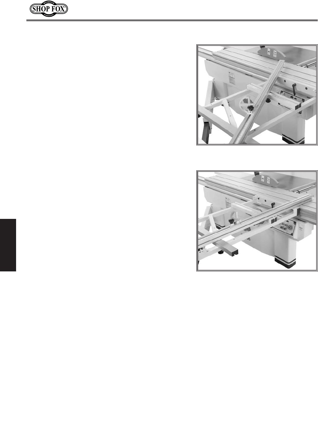
-44-
N(/((('Jc`[`e^KXYc\JXn
FG<I8K@FEJ
D`k\i:lkk`e^
The crosscut fence allows miter cuts from 0˚ through 135˚.
The table mounted miter scale has a resolution of 1˚.
Kfg\i]fidXd`k\iZlk#[fk_\j\jk\gj1
(% Slide the crosscut table to the front edge of the slid-
ing table and lock it in place.
)% Place the crosscut fence center stud in the left or
right stud hole of the crosscut table. The fence can
be installed as shown in =`^li\..for 90˚ to 135˚
cuts, or as shown in =`^li\./for 0˚ to 90˚ cuts.
*% Rotate the fence to the desired angle and lock it in
place.
4. Position the flip stop according to the length of the
workpiece you want to cut off to the left of the
blade.
5. Load the workpiece onto the table saw. The setup
should look similar to Figure ./.
6. Once all the necessary safety precautions have been
taken, perform the cutting operation.
=`^li\..% Fence set-up for 90˚ to 135˚
cuts.
=`^li\./% Example of miter cutting
operation (0˚ to 90˚).
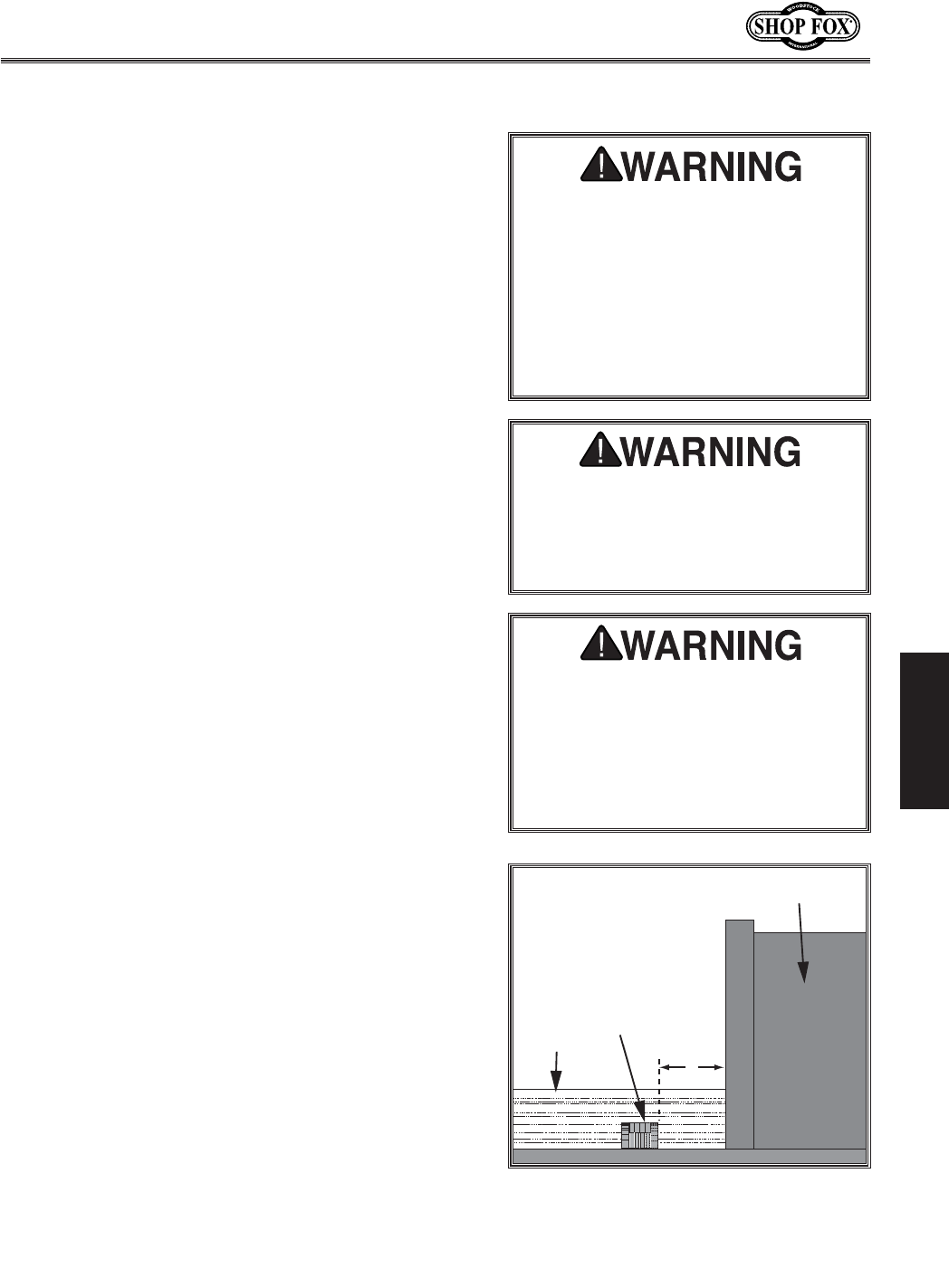
-45-
N(/((('Jc`[`e^KXYc\JXn
FG<I8K@FEJ
;X[f:lkk`e^
Commonly used in furniture joinery, a dado is a straight
channel cut in the face of the workpiece. Dadoes can be
cut using either a dedicated dado blade or a standard saw
blade. Refer to GX^\ */ to install a dado blade on this
saw.
Lj`e^X;X[f9cX[\
The table saw motor is pushed to its limits when cutting
with a dado blade. To reduce the risk of kickback and
personal injury, do not make the full cut in one pass.
Instead make multiple light cuts until the cut reaches the
desired depth.
KfdXb\X[X[fZlkn`k_X[X[fYcX[\#[fk_\j\jk\gj1
1. DISCONNECT THE SAW FROM POWER!
2. Remove the table insert, the blade guard, riving
knife, and the saw blade.
3. Assemble or adjust the dado blade system according
to the dado blade manufacturer’s instructions, then
install the dado blade as instructed on GX^\*/.
4. Raise the dado blade up to the desired depth of cut
(depth of dado channel desired). When cutting deep
dadoes, take more than one pass to reduce the risk of
kickback.
5. Adjust the distance between the rip fence and the
inside edge of the blade, as shown in Figure .0, to
dado the length of a workpiece.
6. If dadoing across the workpiece, use the miter gauge
and carefully line up the desired cut with the dado
blade. DO NOT use the fence in combination with the
miter gauge.
7. Reconnect the saw to the power source.
Nfibg`\Z\ ;X[f9cX[\
=\eZ\
o
=`^li\.0% Cutting with dado blade.
The danger of kickback increases
relative to the depth and width of a
cut. Reduce the risk of kickback by
making multiple passes to achieve the
desired depth of cut. Failure to follow
these warnings could result in serious
personal injury.
Dado operations require proper pro-
cedures to avoid serious injury. Extra
care must be taken to prevent kick-
back when using dado blades. Any
movement of the workpiece away
from the fence will cause kickback. Be
certain that stock is flat and straight.
Failure to follow these warnings could
result in serious personal injury.
DO NOT make a through-cut with
a dado blade. Dado blades are not
designed for through cuts. Failure to
follow this warning could result in
serious personal injury.
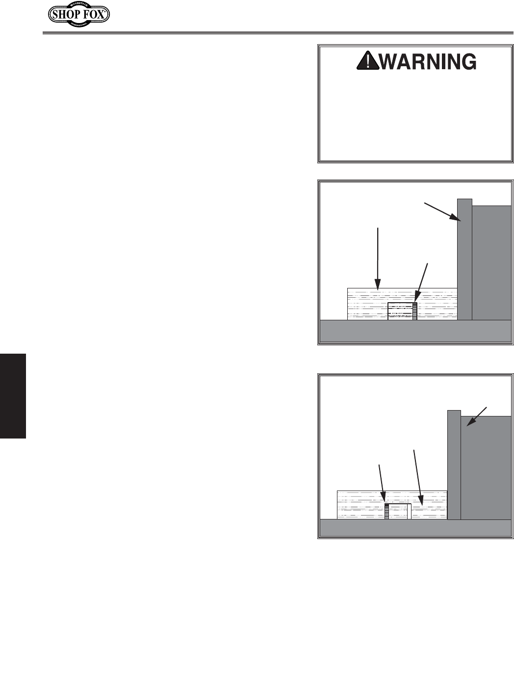
-46-
N(/((('Jc`[`e^KXYc\JXn
FG<I8K@FEJ
8. Turn the saw ON and keep one finger ready to push
the STOP button. The blade should run smooth with
no vibrations.
9. When the blade has reached full speed, perform a
test cut with a scrap piece of wood.
10. If the cut is satisfactory, repeat the cut with the
actual workpiece.
Lj`e^XJkXe[Xi[9cX[\
When making dado cuts with a standard blade, use a
ripping-type blade to reduce motor overloading and blade
wear. Also, you will need to remove the blade guard/dust
hood, but leave the riving knife installed, making sure
that its height is slightly lower than the blade.
KfdXb\X[X[fZlkn`k_XjkXe[Xi[YcX[\#[fk_\j\
jk\gj1
1. DISCONNECT THE SAW FROM POWER!
2. Mark the width of the dado cut on the workpiece.
Include marks on the edge of the workpiece so the
cut path can be aligned when the workpiece is lying
on the table.
3. Raise the blade up to the desired depth of cut (depth
of dado channel). When cutting deep dadoes, take
more than one pass to reduce the risk of kickback.
4. If dadoing across the workpiece, use the miter gauge
to support the workpiece, and align the blade to cut
one of the dado sides. DO NOT use the fence in com-
bination with the miter gauge.
5. If dadoing the length of a workpiece, align the blade
to cut one of the dado sides as shown in Figure /'.
6. Reconnect the saw to the power source and turn the
saw FE. Allow the blade to reach full speed.
7. Perform the cutting operation.
8. Re-adjust the fence so the blade is aligned with the
other edge of the dado channel (Figure /().
Efk\1 Be sure to keep the cuts within your marks;
otherwise, the dado will be too big.
9. Continue making cuts toward the center of the dado
until the dado is complete.
=\eZ\
Nfibg`\Z\
JXn9cX[\
Figure /'. Single-blade dado first cut.
=\eZ\
Nfibg`\Z\
JXn9cX[\
Figure /(. Single-blade dado second cut.
The danger of kickback increases
relative to the depth and width of a
cut. Reduce the risk of kickback by
making multiple passes to achieve the
desired depth of cut. Failure to follow
these warnings could result in serious
personal injury.
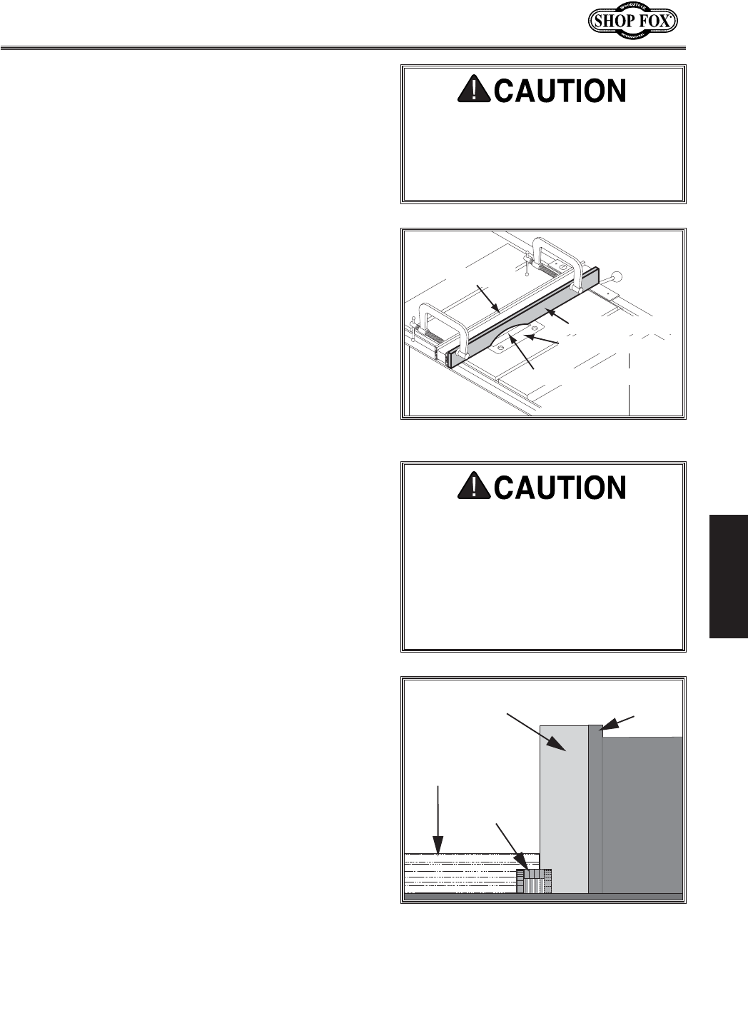
-47-
N(/((('Jc`[`e^KXYc\JXn
FG<I8K@FEJ
IXYY\k:lkk`e^
Commonly used in furniture joinery, a rabbet is an L-shaped
groove cut in the edge of the workpiece. Rabbets can be
cut with either a dado blade or a standard saw blade.
8kkXZ_`e^XJXZi`]`Z`Xc=\eZ\
Rabbet cutting on the edge of the workpiece requires a
sacrificial fence attachment (Figure /)). Make the sacri-
ficial fence the same length as the fence and 3⁄4" thick.
Attach it to the fence with screws or clamps, making sure
they are all secure and tight.
Lj`e^X;X[f9cX[\
When installing the dado blade, remove the special arbor
washer (part #349 in parts breakdown) to allow room for
the blade. A blade flange MUST always be between the
blade and the arbor nut. Refer to the machine data sheet
for the maximum width of dado that this saw can cut.
The table saw motor is pushed to its limits when cutting
with a dado blade. To reduce the risk of kickback and
personal injury, do not make the full cut in one pass.
Instead make multiple light cuts until the cut reaches the
desired depth.
KfdXb\XiXYY\kZlkn`k_X[X[fYcX[\#[fk_\j\
jk\gj1
1. Lower the blade, position the sacrificial fence over
the blade as far as necessary for your rabbet size (see
=`^li\ /*), then start the saw and raise the blade
into the sacrificial fence to the height needed for the
rabbet cut.
Note: N_\e Zlkk`e^ [\\g iXYY\kj# kXb\ dfi\ k_Xe
fe\gXjjkfi\[lZ\k_\i`jbf]b`ZbYXZb%
2. Adjust the fence and align the workpiece to perform
the cutting operation as shown in Figure /*.
3. Reconnect the saw to the power source and turn the
saw ON.
4. When the blade has reached full speed, perform a
test cut with a scrap piece of wood.
5. If the cut is satisfactory, repeat the cut with the final
workpiece.
I`g=\eZ\
JXZi`]`Z`Xc=\eZ\
;X[f@ej\ik
9cX[\:lk$Flk
Figure /). Sacrificial fence.
JXZi`]`Z`Xc=\eZ\ =\eZ\
Nfibg`\Z\
;X[f9cX[\
Figure /*. Rabbet cutting.
Pfl dXp \og\i`\eZ\ b`ZbYXZb [li`e^
k_`j gifZ\[li\% JkXe[ kf k_\ j`[\ f]
k_\ YcX[\ Xe[ n\Xi jX]\kp ^cXjj\j fi
X ]XZ\ j_`\c[ kf gi\m\ek `ealip n_\e
Zlkk`e^iXYY\kj%
8cnXpjlj\glj_jk`Zbj#]\Xk_\iYfXi[j#
glj_gX[[c\j Xe[fk_\ijX]\kp XZZ\j$
jfi`\j n_\e\m\i gfjj`Yc\ kf `eZi\Xj\
jX]\kp Xe[ Zfekifc [li`e^ fg\iXk`fej
k_Xk i\hl`i\ k_\ YcX[\ ^lXi[ Xe[
jgc`kk\ikfY\i\dfm\[]ifdk_\jXn%
8CN8PJi\gcXZ\k_\YcX[\^lXi[X]k\i
[X[f`e^`jZfdgc\k\%
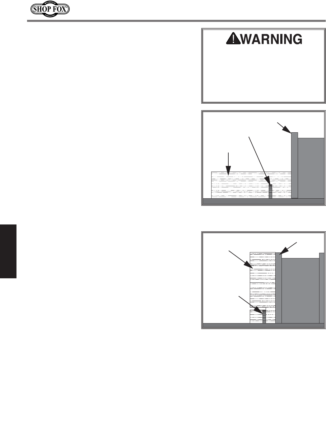
-48-
N(/((('Jc`[`e^KXYc\JXn
FG<I8K@FEJ
Lj`e^XJkXe[Xi[9cX[\
When making rabbet cuts with a standard blade, use a
ripping-type blade to reduce motor overloading and blade
wear. Also, you will need to remove the blade guard/dust
hood, but leave the riving knife installed, making sure
that its height is slightly lower than the blade.
Efk\1Cutting rabbets with a standard saw blade DOES NOT
require the use of a sacrificial fence.
KfdXb\XiXYY\kZlkn`k_XjkXe[Xi[YcX[\#[fk_\j\
jk\gj1
1. DISCONNECT THE SAW FROM POWER!
2. Clearly mark the width of the rabbet cut on the
workpiece.
Efk\1 Include marks on the edge of the workpiece
to clearly identify the intended cut while it is laying
flat on the saw table.
3. Raise the blade up to the desired depth of cut (depth
of rabbet channel desired). When cutting deep rab-
bets, take more than one pass to reduce the risk of
kickback.
4. Adjust the fence so the blade is aligned with the
inside of your rabbet channel as shown in Figure /+.
5. Reconnect the saw to the power source and turn the
saw FE.
6. When the blade has reached full speed, perform a
test cut with a scrap piece of wood.
7. If the cut is satisfactory, repeat the cut with the final
workpiece.
8. Stand the workpiece on edge as shown in Figure /,.
9. Adjust the saw blade height to intersect with the first
cut.
10. Perform the second cut to complete the rabbet.
=\eZ\
JXn9cX[\
Nfibg`\Z\
Figure /+. Rabbet cutting with a standard
blade.
=\eZ\
JXn9cX[\
Nfibg`\Z\
Figure /,. Second cut to create a rabbet.
The danger of kickback increases
relative to the depth and width of a
cut. Reduce the risk of kickback by
making multiple passes to achieve the
desired depth of cut. Failure to follow
these warnings could result in serious
personal injury.
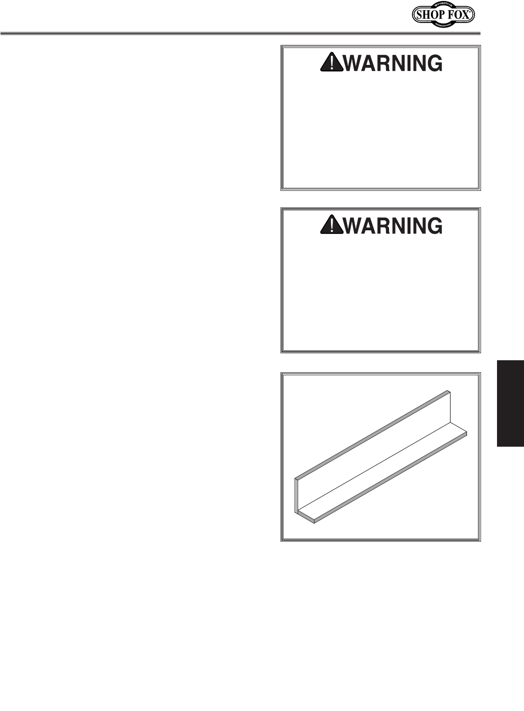
-49-
N(/((('Jc`[`e^KXYc\JXn
FG<I8K@FEJ
I\jXn:lkk`e^
Resawing is the process of cutting a thick piece of stock
into one or more thinner pieces. 9Xe[jXnjXi\`[\Xc]fi
i\jXn`e^Y\ZXlj\k_\pdXb\k_\gifZ\jj]X`icp\Xjp
Xe[jX]\%8kXYc\jXn`jefk`ek\e[\[]fii\jXn`e^Xe[
k_\gifZ\jj`j[`]]`ZlckXe[\oki\d\cp[Xe^\iflj%
Resawing on the table saw increases the risk of binding
the blade and causing kickback. The risk of kickback
increases relative to the depth of a cut. Kickback is
more dangerous when resawing on a table saw because
the blade guard must be removed, leaving no protection
between your hands and the saw blade. Kickback can pull
the operator's hands into the blade, or the operator or
bystanders may be hit by flying stock. DO NOT resaw on a
table saw without using a resaw barrier. DO NOT resaw on
a table saw without wearing a full face shield and making
sure the riving knife is installed.
The following instructions describe how to build a resaw
barrier in order to decrease the risk of resawing cuts.
Efk\1K_`jkXYc\jXnZXefecpi\jXnnff[k_Xk`j-fi
c\jj%
I\jXn9Xii`\i
The resaw barrier shown in =`^li\/- holds the workpiece
vertical, keeps it aligned with the fence, and keeps your
hands away from the blade.
Components Needed for the Resaw Barrier:
Hardwood or Plywood 3⁄4" x 41⁄4" x 27" .....................1
Hardwood or Plywood 3⁄4" x 3" x 27" .........................1
Wood Screws 2" .................................................8
Wood Glue ........................................... As Needed
Tools Needed for the Resaw Barrier:
Table Saw ........................................................1
Jointer and Planer ............................. Recommended
Clamps ................................................2 Minimum
Drill and Drill Bits ...............................................1
KfYl`c[k_\i\jXnYXii`\i#[fk_\j\jk\gj1
(% Cut two boards to 3⁄4" x 41⁄4" x 27" and 3⁄4" x 3" x
27". If you are using hardwood, cut the boards over-
size, then joint and plane the boards to the correct
size to make sure the boards are square and flat.
Efk\1Fecplj\]lie`kli\^iX[\gcpnff[fib`ce$[i`\[
_Xi[nff[kfgi\m\eknXig`e^%
=`^li\/-% Resawing barrier.
I\jXn`e^feXkXYc\jXn`eZi\Xj\jk_\
Z_XeZ\j f] b`ZbYXZb% Serious injury
can be caused by kickback. Kickback
is a high-speed expulsion of stock
from the table saw toward an opera-
tor. The operator or bystanders may
be struck by flying stock, or the oper-
ator’s hands can be pulled into the
blade during the kickback.
Resawing operations require proper
procedures to avoid serious injury.
Extra care must be taken to prevent
kickback when resawing. Any tilting
or movement of the workpiece away
from the fence will cause kickback. Be
certain that stock is flat and straight.
Failure to follow these warnings could
result in serious personal injury.
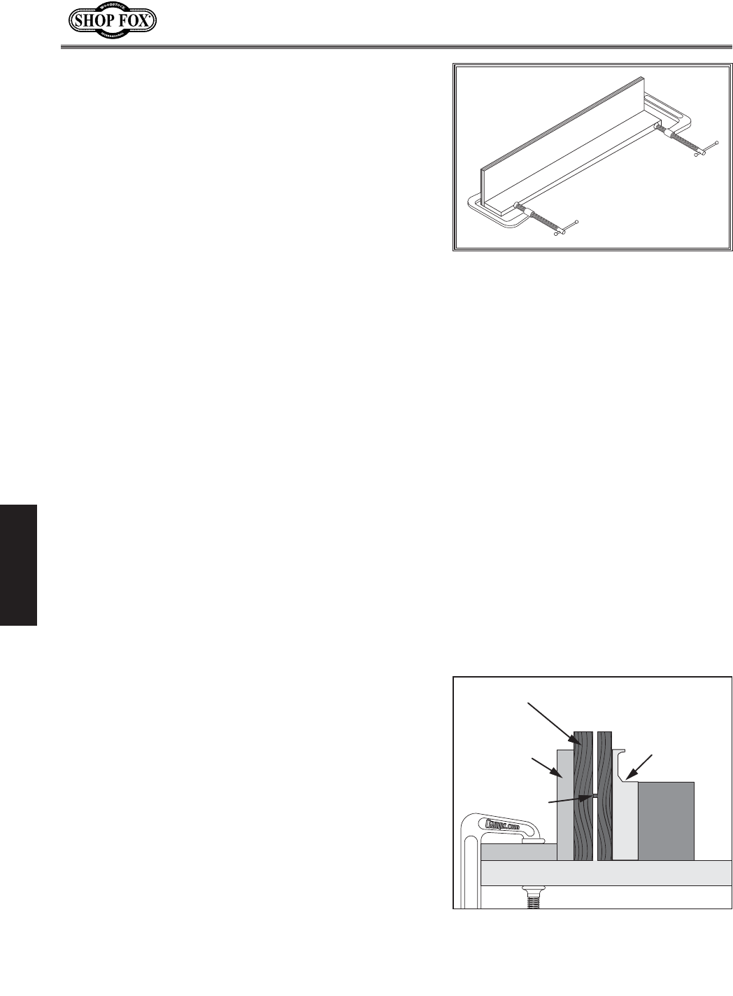
-50-
N(/((('Jc`[`e^KXYc\JXn
FG<I8K@FEJ
)% Pre-drill and countersink 8 pilot holes approximately
3⁄8" from the bottom of the 41⁄4" tall board.
*% Glue the end of the 3" board, then clamp the boards
at a 90° angle with the larger board in the vertical
position as shown in =`^li\/..
+% Secure the joint with wood screws through the pilot
holes made in Jk\g).
I\jXn`e^Fg\iXk`fej
The table saw motor is pushed to its limits when
resawing. If the motor starts to bog down, slow down
your feed rate. Motor overloading and blade wear can
be reduced by using a ripping blade. Ripping blades are
designed to clear the sawdust quickly.
Components Needed for Resawing:
Zero Clearance Insert ..........................................1
Ripping Blade 10" ...............................................1
Clamps ............................................................2
Shop Made Auxiliary Fence ....................................1
Shop Made Resaw Barrier ......................................1
Kfg\i]fidi\jXn`e^fg\iXk`fej#[fk_\j\jk\gj1
(% DISCONNECT THE SAW FROM POWER!
)% Remove the standard table insert and the blade
guard/splitter. Install a ripping blade and lower the
blade below the table surface.
*% Attach the auxiliary fence to the standard fence and
set it to the desired width.
Efk\1N_\e]`^li`e^flkk_\Zfii\Zkn`[k_#[fek
]fi^\kkfXZZflek]fiYcX[\b\i]Xe[k_\`eXZZliXZp
f]k_\]\eZ\jZXc\n_`c\k_\Xlo`c`Xip]\eZ\`j
`ejkXcc\[%
+% Place the workpiece against the fence and slide the
resaw barrier against the workpiece. Now clamp the
resaw barrier to the top of the table saw (see =`^li\
//).
,% Slide the workpiece over the blade to make sure it
moves smoothly.
=`^li\/.% Clamping the resawing barrier.
I`g=\eZ\
I\jXn
9Xii`\i
(&/
:fee\Zk`fe
Nfibg`\Z\
=`^li\//% Ideal completed resaw cut.
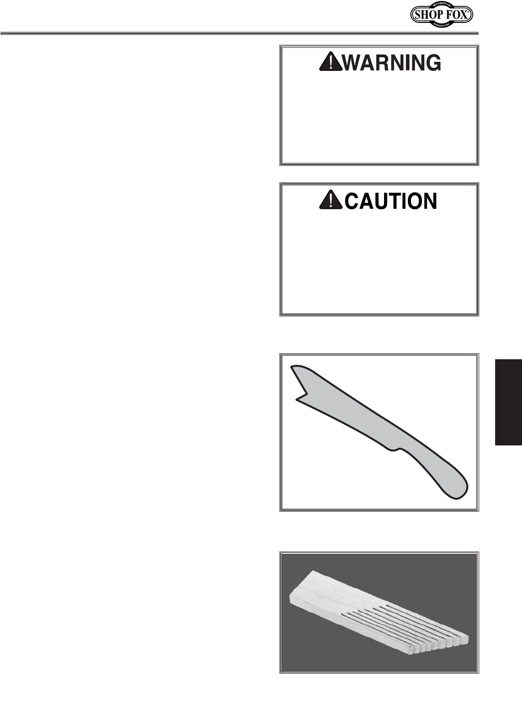
-51-
N(/((('Jc`[`e^KXYc\JXn
FG<I8K@FEJ
-% Raise the blade approximately an inch, or close to
half the height of the workpiece (=`^li\//), which-
ever is less.
.% Plug in the table saw, turn it FE, and use a push
stick to feed the workpiece through the blade, using
a slow and steady feed rate.
/% Flip the workpiece end for end, keeping the same
side against the fence, and run the workpiece
through the blade.
0% Repeat Jk\gj-Æ/ until the blade is close to half
of the height of the board to be resawn. The ideal
completed resaw cut will leave an 1⁄8" connection
when the resawing is complete as shown in =`^li\
//. Leaving an 1⁄8" connection will reduce the risk of
kickback.
('% Turn F== the table saw, then separate the parts of
the workpiece and hand plane the remaining ridge.
((% When finished resawing, remove the resaw barrier
and re-install the blade guard/splitter.
The danger of kickback increases
relative to the depth and width of a
cut. Reduce the risk of kickback by
making multiple passes to achieve the
desired depth of cut. Failure to follow
these warnings could result in serious
personal injury.
8cnXpjlj\glj_jk`Zbj#]\Xk_\iYfXi[j#
glj_gX[[c\j Xe[fk_\ijX]\kp XZZ\j$
jfi`\j n_\e\m\i gfjj`Yc\ kf `eZi\Xj\
jX]\kp Xe[ Zfekifc [li`e^ fg\iXk`fej
k_Xk i\hl`i\ k_\ YcX[\ ^lXi[ Xe[
jgc`kk\ikfY\i\dfm\[]ifdk_\jXn%
ALWAYS replace the blade guard after
resawing is complete.
J_fg$DX[\JX]\kp
8ZZ\jjfi`\j
Shop-made safety accessories can reduce the risk of
injury while operating the table saw.
There are dozens of useful shop-made accessories for the
table saw, but two of the most common items that can be
easily made are push sticks and featherboards.
• Glj_Jk`Zbj made from the shop are very popular
among table saw owners because they are inexpen-
sive and easy to make. Particularly good are those
that keep your hand a safe distance away from the
blade, offer stable support and grip, and are com-
fortable in the hand. =`^li\/0 shows an illustration
of a simple push stick.
• =\Xk_\iYfXi[j similar to the one in =`^li\0' make
good anti-kickback devices. To use these, they must
be clamped to the table or fence. The angled ends
and flexibility of the fingers allow the workpiece to
move in one direction and lock up if the workpiece
moves backwards.
=`^li\/0% Illustration of a simple push
stick.
=`^li\0'% Anti-kickback featherboard.

-52-
N(/((('Jc`[`e^KXYc\JXn
D8@EK<E8E:<
D8@EK<E8E:<
Tables can be kept rust-free with regular applications of products like SLIPIT®. For long term storage
you may want to consider products like Boeshield T-9™.
KXYc\9Xj\
Frequently blow off sawdust with compressed air. This is especially important for the internal working
parts and motor. Dust build-up around the motor is a sure way to decrease its lifespan.
Occasionally it will become necessary to clean the internal parts with more than compressed air. To do
this, remove the table top and clean the internal parts with a citrus cleaner or mineral spirits and a stiff
brush (a toothbrush works well in tight spaces). Make sure the internal workings are dry before using the
saw again so that wood dust will not accumulate. If any essential lubrication is removed during cleaning,
relubricate those areas.
:c\Xe`e^
For optimum performance from your machine, follow this
maintenance schedule and refer to any specific instructions
given in this section.
;X`cp:_\Zb1
• Loose mounting bolts.
• Worn or damaged saw blades.
• Worn or damaged switches or wires.
• Any other unsafe condition.
N\\bcpDX`ek\eXeZ\1
• Clean sliding table surface and grooves.
• Clean the cast iron saw table.
• Clean the sliding table roller guideways.
• Clean the rip fence and sliding grooves.
• Clean the rip fence bracket.
Dfek_cp:_\Zb1
• Clean/vacuum dust buildup from inside cabinet and
off motor.
• V-belt tension, damage, or wear.
Efk\1Kf\ejli\fgk`dldgfn\ikiXejd`jj`fe]ifdk_\
dfkfikfk_\YcX[\j#k_\Y\ckjdljkY\`e^ff[Zfe[`k`fe
]i\\]ifdZiXZbj#]iXp`e^Xe[n\Xi Xe[fg\iXk\le[\i
gifg\ik\ej`fe%
JZ_\[lc\
D8B< JLI< k_Xk pfli dXZ_`e\ `j
legcl^^\[[li`e^ Xcc dX`ek\eXeZ\gif$
Z\[li\j@]k_`jnXie`e^`j`^efi\[#j\i`$
fljg\ijfeXc`ealipdXpfZZli%
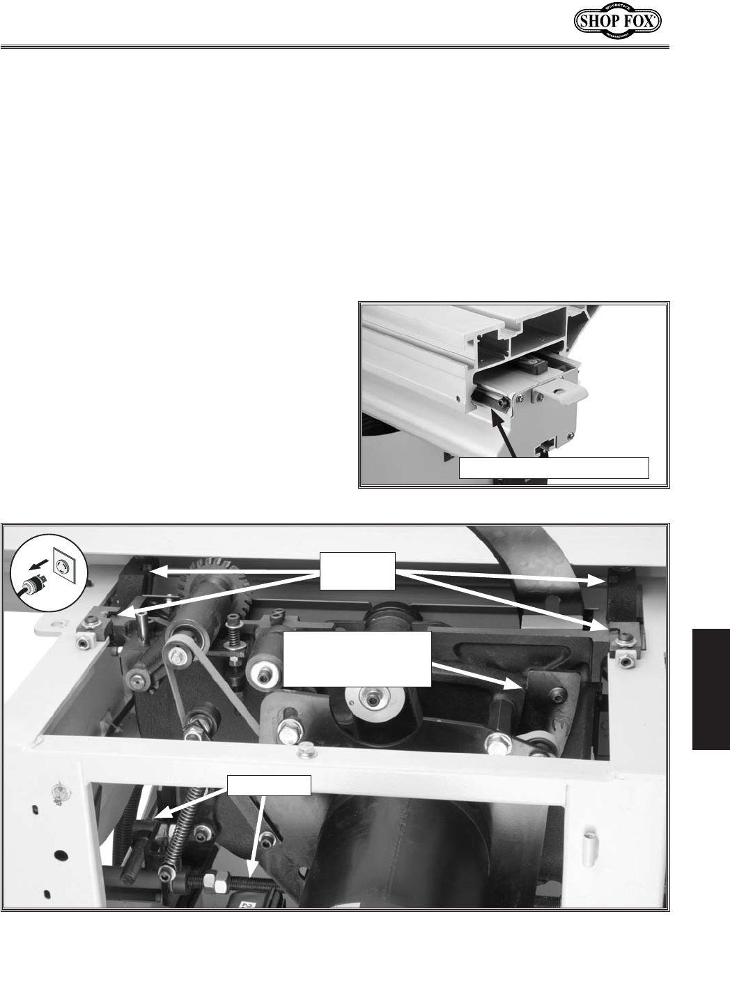
-53-
N(/((('Jc`[`e^KXYc\JXn
D8@EK<E8E:<
ClYi`ZXk`fe
9\Xi`e^j1 The bearings are sealed and pre-lubri-
cated and require no lubrication.
Kilee`fej1 Use multi-purpose grease in the
trunnion grooves (=`^li\0)) every 6–12 months,
depending on the frequency of use. To grease the
blade height trunnion, move the blade height all
the way down and smear a dab of grease into
the trunnion groove, behind the plate shown in
=`^li\0), then move the blade up all the way
to spread the grease.
To grease the blade tilt trunnions, move the
sliding table out of the way and open the blade
guard. Tilt the blade to 90°. From the front of
the saw, smear a dab of grease in the front of
the trunnion grooves on both sides. Now, tilt the
blade to 45° and reach inside the cabinet and
smear a dab of grease into the back of the trun-
nion grooves on both sides. Tilt the blade back-
and-forth to distribute the grease evenly.
=`^li\0(% Sliding table ways.
Sliding Table Way Steel Rod
=`^li\0)% Lubrication locations (table removed for clarity).
Blade Height Trunnion
(Grease Behind This
Plate)
Leadscrews
Blade Tilt
Trunnions
C\X[jZi\nj1 Use multi-purpose grease on the
leadscrews (=`^li\ 0)) every 6-12 months, at
the same time you lubricate the trunnions. Wipe
the leadscrews clean with a dry rag and brush a
light coat of new grease on them with a clean,
dry brush. Only grease the area of the leadscrew
between the stop nuts. Move the blade height
and tilt the blade back-and-forth to distribute
the grease evenly.
Jc`[`e^KXYc\NXpj1 Spray/wipe on a light
machine oil (such as Boeshield) down the entire
length of the steel rods (=`^li\0().
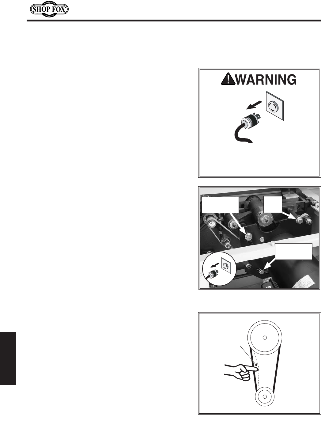
-54-
N(/((('Jc`[`e^KXYc\JXn
J<IM@:<
J<IM@:<
This section covers the most common service adjustments
or procedures that may need to be made during the life
of your machine.
If you require additional machine service not included
in this section, please contact Woodstock International
Technical Support at (360) 734-3482 or send e-mail to:
k\Z_$jlggfik7j_fg]fo%Y`q.
>\e\iXc
D8B< JLI< k_Xk pfli dXZ_`e\ `j
legcl^^\[ [li`e^ Xcc j\im`Z\ gifZ\$
[li\j @] k_`j nXie`e^ `j `^efi\[# j\i`$
fljg\ijfeXc`ealipdXpfZZli%
DX`e9\ckI\gcXZ\d\ek
(% DISCONNECT SAW FROM POWER!
)% Tilt the blade to 45˚ and lower it as far as it will go.
*% Remove the motor cabinet door.
+% Loosen the pivot bolt and two adjustment bolts
(=`^li\0*).
Efk\1;FEFKcffj\ek_\j\Yfckjdfi\k_Xe(Ð)fi
pflilek_\i`jbf]k_\dfkfidflekYfckjZfd`e^
flkf]k_\`i_fc\j#n_`Z_n`ccY\[`]]`Zlckkfk_i\X[
YXZb`e%
,% Push and hold the motor all the way up to relieve
tension on the belt, remove the belts from the top
pulley, and squeeze them between the lower pulley
and casting.
-% Fit the new belts onto the pulleys in the same man-
ner that you removed the old belts.
.% Push down on the motor with one hand, and tighten
the adjustment and pivot bolts with the other hand
or have someone help you. The belts should be tight
enough that they only deflect approximately 1⁄4"
when pushed in the center with your thumb or index
finger with moderate force.
/% Replace the motor cabinet door.
9\ckJ\im`Z\
Glcc\p
;\]c\Zk`fe
Glcc\p
=`^li\0+% Checking belt deflection.
=`^li\0*% Main blade belt tension
controls (table removed for clarity).
Adjustment
Bolt
Pivot
Bolt
Adjustment
Bolt
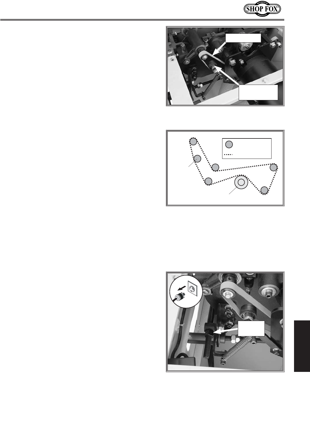
-55-
N(/((('Jc`[`e^KXYc\JXn
J<IM@:<
JZfi`e^9\ckI\gcXZ\d\ek
(% DISCONNECT SAW FROM POWER!
)% Tilt the blade to 45˚ and lower it as far as it will go.
*% Remove the motor cabinet door.
+% Pull the tensioner away from the scoring belt (=`^li\
0,) to relieve belt tension and remove the scoring
belt from the pulleys.
Efk\1Kliek_\Y\ckj`[\nXpjkfjhl\\q\k_\]cXk
gXikk_ifl^_k_\jdXcc^XgY\kn\\ek_\Yfkkfdglc$
c\pXe[k_\ZXjk`e^%
,% Put the new scoring belt on the pulleys as shown in
=`^li\0-, and push the tensioner against the scor-
ing belt to take up any slack.
-% Replace the motor cabinet door.
9cX[\K`ck:Xc`YiXk`fe
The blade tilt is calibrated at the factory, but can be
recalibrated if it changes during the life of the machine.
The 0° stop positions the blade square with the table.
'Jkfg
(% DISCONNECT SAW FROM POWER!
)% Move the blade tilt to 0° according to the gauge,
and raise the main blade as far as it will go.
*% Use a machinist's square to check if the blade is
square to the table.
— If the blade is not square to the table, loosen the
two set screws that secure the 0˚ tilt stop nut
shown in =`^li\0.%
+% Adjust the stop nut and recheck the blade tilt as
many times as necessary until the blade is square to
the table.
,% Tighten the two set screws in the stop nut.
-% Check the blade tilt pointer mechanism to ensure
that it points to 0°.
— If the blade tilt pointer shows an incorrect tilt,
adjust it by loosening the cap screws, rotating the
pointer until it points to 0°, then tightening the
cap screws.
Scoring Belt
Tensionser
=`^li\0,% Replacing the scoring motor
belt (table removed for clarity).
Scoring Belt
IZch^dcZg
BdidgEjaaZn
2EjaaZn$GdaaZg
2HXdg^c\7Zai
=`^li\0-% Scoring belt installation
configuration.
=`^li\0.% Blade tilt stop nut (0°).
0° Tilt
Stop Nut
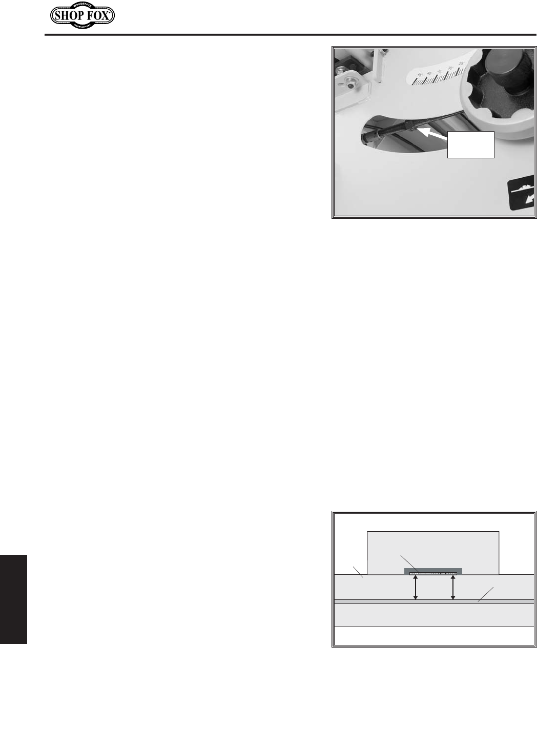
-56-
N(/((('Jc`[`e^KXYc\JXn
J<IM@:<
+,Jkfg
(% DISCONNECT SAW FROM POWER!
)% Adjust the blade angle until it hits the 45° positive
stop and check the blade angle with a 45° square.
— If the blade is not 45° to the table, loosen the two
set screws that secure the 45˚ tilt stop nut shown
in =`^li\0/%(This nut can also be accessed from
the front of the saw by moving the sliding table all
the way forward.)
*% Adjust the stop nut and recheck the blade tilt as
many times as necessary until the blade is 45° to the
table.
+% Tighten the two set screws in the stop nut.
Jc`[`e^KXYc\GXiXcc\c`jd
The table is calibrated at the factory, but can be adjusted
slightly if it is not parallel to the blade.
Besides the tools included with the saw, this procedure
requires a felt tip pen, an adjustable square, and a set of
feeler gauges or a dial indicator.
Efk\1Lj`e^X[`Xc`e[`ZXkfin`ccgifm`[\dlZ_dfi\
XZZliXk\i\jlckj%
KfX[aljkk_\jc`[`e^kXYc\gXiXcc\cn`k_k_\dX`eYcX[\#
[fk_\j\jk\gj1
(% DISCONNECT SAW FROM POWER!
)% Move the blade tilt to 0˚ (blade 90˚ to table), and
raise the main blade up to maximum height.
*% Mark the edge of the blade with a felt tip pen. This
will allow you to take your measurements from the
exact same place on the blade.
+% Using an adjustable square or a dial indicator, mea-
sure the distance (A) between the miter slot and the
front of the blade, as shown in =`^li\00.
,% Rotate the blade 180° and slide the table with the
measuring device to position B.
9cX[\
KXYc\
D`k\iJcfk
98
=`^li\00% Measuring gap between the
table and the blade.
=`^li\0/% 45° Blade tilt stop nut.
45° Tilt
Stop Nut
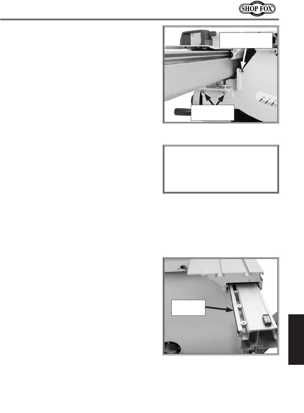
-57-
N(/((('Jc`[`e^KXYc\JXn
J<IM@:<
Jc`[`e^KXYc\8[aljkd\ek
The sliding table features an adjustment bar with bolts
that control how easily the sliding table moves across the
base (see =`^li\('(). These adjustment bolts are factory
set. They can only be accessed by removing the end covers
from both ends of the sliding table base and sliding the
plastic plate out of the way.
If the adjustment bolts do require adjustments, turning
them counterclockwise increases pressure against the steel
rails. This reduces table movement slop, which increases
accuracy, but makes it harder to slide the table.
Turning the adjustment bolts clockwise decreases the
pressure against the steel rails. This increases table move-
ment slop, which reduces accuracy, but makes it easier to
slide the table.
Adjusting this part of the sliding table correctly is a matter
of trial-and-error by making adjustments, moving the slid-
ing table, then making additional adjustments. Ultimately,
the table must move easily without any slop.
-% Measure the difference between the two positions
(use the feeler gauge if using the adjustable square).
Make note of the difference between the two mea-
surements.
— If the gap is the same on both sides or the differ-
ence is 0.004" or less, no adjustments to the table
parallelism need to be made.
— If the difference is greater than 0.004", then
the sliding table parallelism must be adjusted.
Proceed to Jk\g..
.% Loosen the sliding table mounting nuts (see =`^li\
('') at both mounting locations.
/% At the side of the table that needs to move, loosen
the hex nut on the parallel adjustment screw.
0% Slowly rotate the parallel adjustment screw (=`^li\
('') as necessary to move the table. If you move
the adjustment screw away from the table, then
push the table against the screw before proceeding.
('% Tighten the hex nut on the parallel adjustment
screw to secure it in place, and tighten the table
mounting nuts.
((% Repeat Jk\gj+Æ- to ensure the table didn't move.
Figure (''. Table parallelism adjustment
controls.
Parallel
Adjustment Screw
Table Mounting
Nuts
=`^li\('(% Adjustment bolt access
location.
Adjustment
Bolt
EFK@:<
@] k_\ jc`[`e^ kXYc\ n`cc efk dfm\ ]Xi
\efl^_kf Y\Zfd\ gXiXcc\c#k_\ YcX[\
kilee`feje\\[kfY\j_`]k\[%:XccK\Z_
Jlggfik%
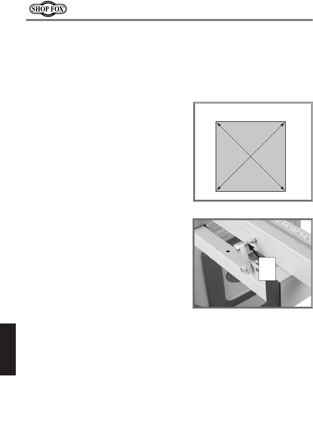
-58-
N(/((('Jc`[`e^KXYc\JXn
J<IM@:<
:Xc`YiXk`e^:ifjjZlk
=\eZ\0'Jkfgj
Squaring the crosscut fence to the blade ensures that
cuts made with the crosscut fence will be square. This
procedure can be done by using a piece of scrap plywood
as a test piece and making five test cuts, then adjusting
the fence as necessary.
To square the crosscut fence with the blade, do these
steps:
(% Make sure the blade is parallel with the sliding table
and that the crosscut fence is resting against the 90°
stop bolt (see =`^li\('* for locations).
)% Prepare the scrap test piece by cutting it to 32" x
32", then number all four sides of the test piece.
*% Use the crosscut fence to cut 1⁄2" off of each side of
the test piece, then cut side 1 again (make five cuts
total).
+% Measure the test piece diagonally from corner-to-
corner as shown in =`^li\(').
— If both measurements are not within 1⁄16", then
the crosscut fence needs to be adjusted. Proceed
to Jk\gj,Æ/.
— If both measurements are within 1⁄16" then no
adjustments need to be made. You are finished
with this procedure.
,% Loosen the knob on the crosscut fence to allow it to
pivot (make sure 90° stop bolt remains against the
fence during adjustments).
-% Loosen the hex nut on the 90° stop bolt shown in
=`^li\('*, and rotate the 90° stop bolt to square
the crosscut fence.
.% Tighten the hex nut on the 90° stop bolt, then tight-
en the crosscut fence knob, making sure the block is
touching the 90° stop bolt.
/% Repeat Jk\gj*$+.
K\jkG`\Z\
(
)
*
+
Figure ('). Fence adjustment test piece.
Figure ('*. Crosscut fence adjustment
cam.
90°
Stop
Bolt
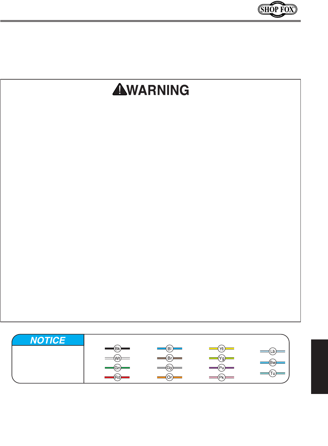
-59-
N(/((('Jc`[`e^KXYc\JXn
J<IM@:<
These pages are current at the time of printing. However, in the spirit of improvement, we may make
changes to the electrical systems of future machines. Study this diagram carefully. If you notice differ-
ences between your machine and these wiring diagrams, call Woodstock International Technical Support
at (360) 734-3482.
(% J?F:B?8Q8I;% Working on wiring that is
connected to a power source is extremely
dangerous. Touching electrified parts will
result in personal injury including but not
limited to severe burns, electrocution,
or death. Disconnect the power from
the machine before servicing electrical
components!
)% HL8C@=@<;<C<:KI@:@8E% Due to the
inherent hazards of electricity, only a
qualified electrician should perform wiring
tasks on this machine. If you are not a
qualified electrician, get help from one
before attempting any kind of wiring job.
*% N@I<:FEE<:K@FEJ% All connections must
be tight to prevent wires from loosening
during machine operation. Double-check all
wires disconnected or connected during any
wiring task to ensure tight connections.
+% N@I<&:FDGFE<EK;8D8><% Damaged
wires or components increase the risk of
serious personal injury, fire, or machine
damage. If you notice that any wires or
components are damaged while performing
a wiring task, replace those wires or
components before completing the task.
,% :@I:L@KI<HL@I<D<EKJ% You MUST
follow the requirements on GX^\() when
connecting your machine to a power
source.
-% DFKFIN@I@E>% The motor wiring shown
in these diagrams is current at the time
of printing, but it may not match your
machine. Always use the wiring diagram
inside the motor junction box.
.% :8G8:@KFIJ% Some capacitors store an
electrical charge for up to five minutes
after being disconnected from the power
source. To avoid being shocked, wait
at least this long before working on
capacitors.
/% DF;@=@:8K@FEJ% Using aftermarket parts or
modifying the wiring beyond what is shown
in the diagram may lead to unpredictable
results, including serious injury or fire.
0% <OG<I@<E:@E>;@==@:LCK@<J% If you are
experiencing difficulties understanding
the information included in this section,
contact our Technical Support at (360) 734-
3482.
<c\Zki`ZXcJX]\kp@ejkilZk`fej
The photos and diagrams
included in this section are
best viewed in color. You
can view these pages in
color at www.shopfox.biz.
BLACK
WHITE
GREEN
RED
BLUE
BROWN
GRAY
ORANGE
YELLOW
YELLOW
GREEN
PURPLE
PINK
LIGHT
BLUE
BLUE
WHITE
TUR-
QUOISE
WIRING DIAGRAM COLOR KEY
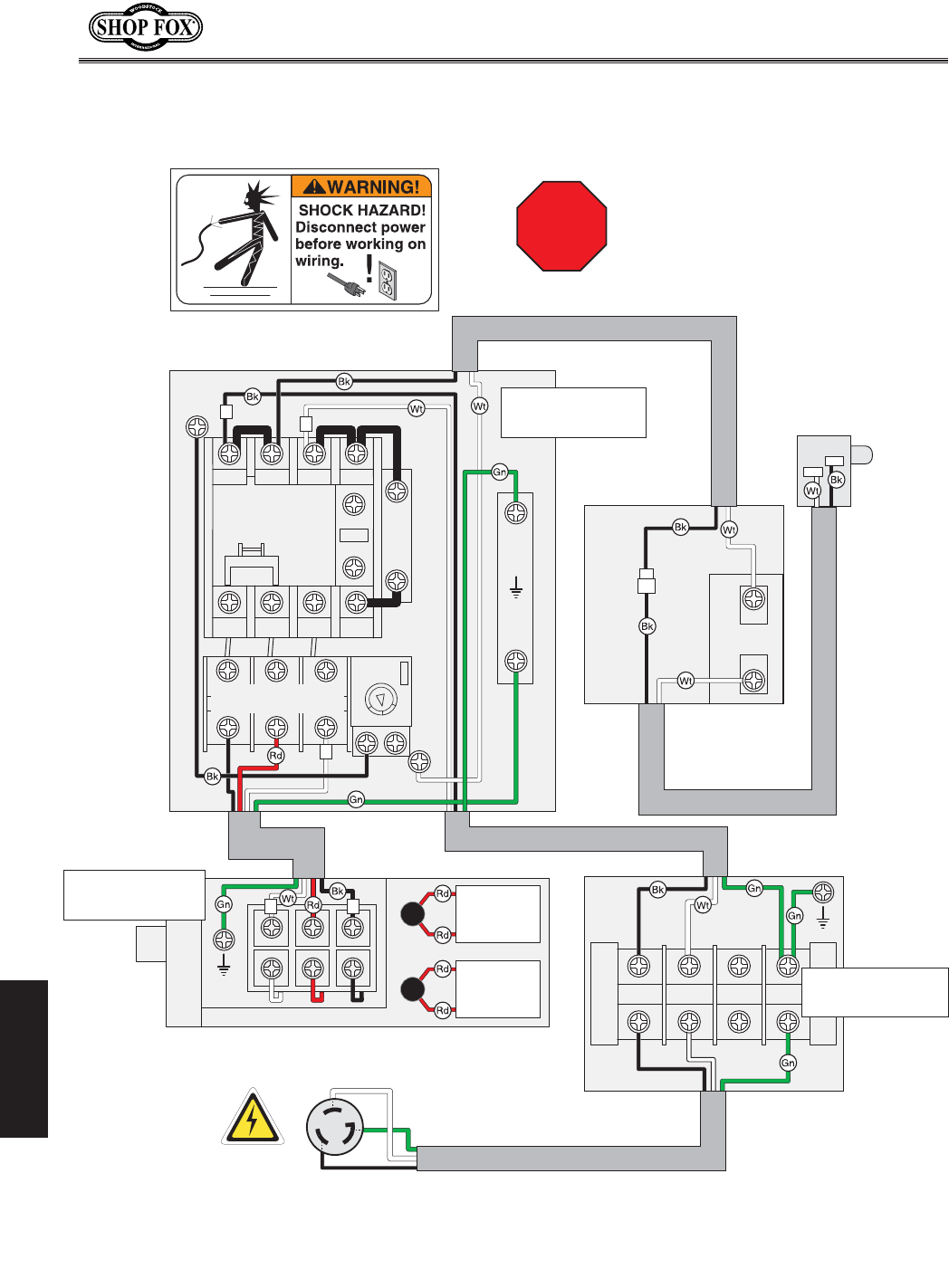
-60-
N(/((('Jc`[`e^KXYc\JXn
J<IM@:<
N`i`e^;`X^iXd
6
6BE
G:H:I
.+ .-
I&$' I($+ CD&)
I'$)
A&$& A($* CD&(
A'$(
.*
''
'-
()
H:I5'*
C8&*
H9:
C8&+
>ifle[
&$' ($) *$+
FCI<C8PI8$*'
JkXik
:XgXZ`kfi
+''D=;
),'M8:
Ile
:XgXZ`kfi
*'D=;
,''M8:
& ' ( )
<D<I><E:P
JKFGJN@K:?
D8>E<K@:JN@K:?
8JJ<D9CP
DFKFI,?G))'MJ@E>C<$G?8J<
C-$*'GCL>8JI<:FDD<E;<;
J;<D8$(/
))'M
>ifle[
?fk
?fk
220 VAC
G
X
Y
GFN<I
:FEE<:K@FE
9FO
9C8;<>L8I;
C@D@KJN@K:?
&'
K
GH
FE
<gdjcY
<gdjcY
J
K
See =`^li\('-
on GX^\-(
See =`^li\(',
on GX^\-(
See =`^li\('+
on GX^\-(
JKFG
Read
Page 59
Before
Wiring
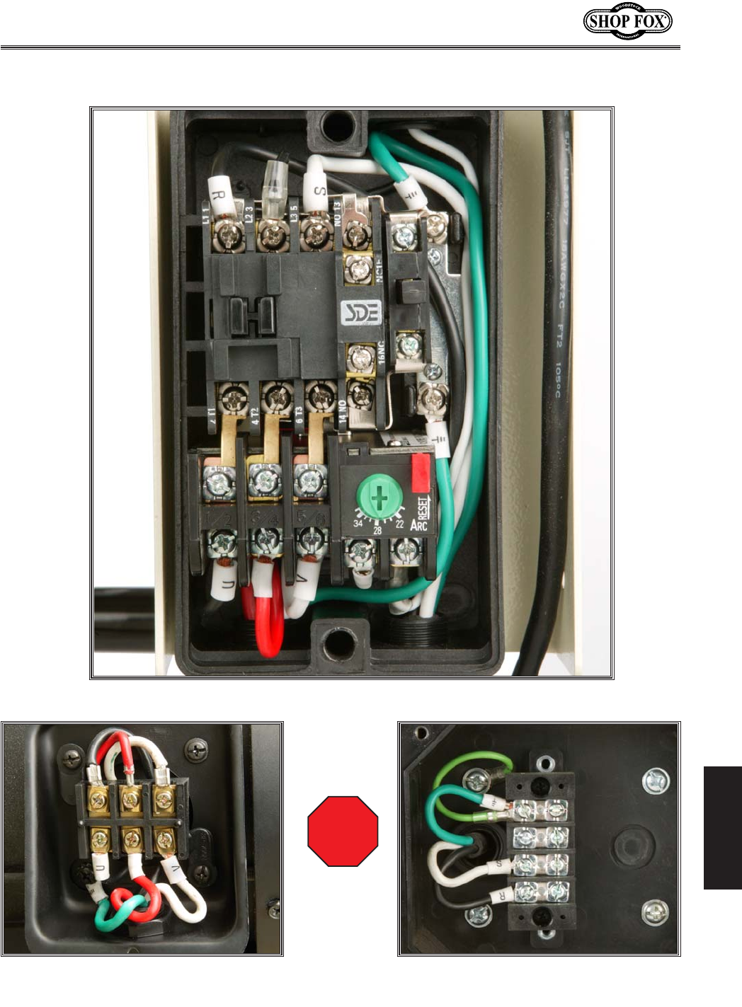
-61-
N(/((('Jc`[`e^KXYc\JXn
J<IM@:<
<c\Zki`ZXcG`Zkli\j
=`^li\('+% Magnetic switch.
=`^li\(',% Motor junction box. =`^li\('-% Power connection junction
box.
JKFG
Read
Page 59
Before
Wiring

-62-
N(/((('Jc`[`e^KXYc\JXn
J<IM@:<
KiflYc\j_ffk`e^
This section covers the most common problems and corrections with this type of
machine. N8IE@E>;FEFKdXb\XepX[aljkd\ekjlek`cgfn\i`j[`jZfee\Zk\[Xe[
dfm`e^gXikj_Xm\Zfd\kfXZfdgc\k\jkfg
GIF9C<D GFJJ@9C<:8LJ< :FII<:K@M<8:K@FE
Machine does not start or a
breaker trips.
1. Emergency stop push-button is
engaged/faulty.
2. Power supply switched OFF or is at
fault.
3. Blade guard limit switch engaged/
at fault.
4. Motor connection wired incorrect-
ly.
5. Thermal overload relay has
tripped.
6. Wall fuse/circuit breaker is blown/
tripped.
7. Contactor not getting energized/
has burnt contacts.
8. Wiring is open/has high resistance.
9. Motor ON button or ON/OFF switch
is at fault.
10. Motor is at fault.
1. Rotate clockwise slightly until it pops out/replace
it.
2. Ensure power supply is switch on; ensure power sup-
ply has the correct voltage.
3. Move blade guard to the working position; replace
faulty limit switch.
4. Correct motor wiring connections.
5. Turn cut-out dial to increase working amps and push
the reset pin. Replace if tripped multiple times
(weak relay).
6. Ensure circuit size is suitable for this machine;
replace weak breaker.
7. Test for power on all legs and contactor operation.
Replace unit if faulty.
8. Check for broken wires or disconnected/corroded
connections, and repair/replace as necessary.
9. Replace faulty ON button or ON/OFF switch.
10. Test/repair/replace.
Machine stalls or is under-
powered.
1. Feed rate/cutting speed too fast
for task.
2. Workpiece material is not suitable
for this machine.
3. Belt(s) slipping.
4. Motor connection is wired incor-
rectly.
5. Motor bearings are at fault.
6. Start delay module is at fault.
7. Motor is at fault.
1. Decrease feed rate/cutting speed.
2. Only cut wood products; make sure moisture con-
tent is below 20% and there are no foreign materials
in the workpiece.
3. Replace bad belt(s), align pulleys, and re-tension.
4. Correct motor wiring connections.
5. Test by rotating shaft; rotational grinding/loose
shaft requires bearing replacement.
6. Adjust to correct delay; replace module.
7. Test/repair/replace.
Dfkfi<c\Zki`ZXc

-63-
N(/((('Jc`[`e^KXYc\JXn
J<IM@:<
GIF9C<D GFJJ@9C<:8LJ< :FII<:K@M<8:K@FE
Machine has vibration or
noisy operation.
1. Motor or component is loose.
2. Blade is at fault.
3. Belt(s) worn or loose.
4. Pulley is loose.
5. Motor mount loose/broken.
6. Machine is incorrectly mounted or
sits unevenly.
7. Arbor pulley is loose.
8. Motor fan is rubbing on fan cover.
9. Arbor bearings are at fault.
10. Motor bearings are at fault.
1. Inspect/replace stripped or damaged bolts/nuts,
and re-tighten with thread locking fluid.
2. Replace warped, bent, or twisted blade; resharpen
dull blade.
3. Inspect/replace belts (refer to Page 54).
4. Realign/replace shaft, pulley, setscrew, and key as
required.
5. Tighten/replace.
6. Tighten/replace anchor studs in floor; relocate/shim
machine.
7. Retighten/replace arbor pulley with shaft and thread
locking liquid.
8. Replace dented fan cover; replace loose/damaged
fan.
9. Replace arbor housing bearings; replace arbor.
10. Test by rotating shaft; rotational grinding/loose
shaft requires bearing replacement.
Fg\iXk`fe
GIF9C<D GFJJ@9C<:8LJ< :FII<:K@M<8:K@FE
Workpiece has burned
edges, binds, or kicks
back.
1. Sliding table is not parallel to
blade.
2. Riving knife is not aligned with the
blade.
3. Blade is warped.
1. Make sliding table parallel to the
blade (Page 56).
2. Shim the riving knife to align it with the main
blade.
3. Replace the blade.
Workpiece has chip out on
the bottom edge.
1. Scoring blade height is incorrect.
2. Scoring blade is not aligned with
the main blade.
3. Scoring blade kerf does not match
the main blade.
1. Adjust the height of the scoring blade.
2. Align the scoring blade (Page 37).
3. Adjust the scoring blade kerf (Page 37).
Sliding table saw does not
cut square.
1. Sliding table is not parallel to
blade.
2. Rip fence is not parallel to blade.
3. Crosscut fence is not perpendicular
to the blade.
1. Adjust the sliding table (Page 56).
2. Adjust the rip fence parallel to blade.
3. Adjust the crosscut fence perpendicular to the blade
(Page 58).
Fence hits table top when
sliding across table.
1. Front rail is too low.
2. Rip fence roller is too low.
1. Raise the front rail.
2. Adjust the rip fence roller.
Blade does not reach 90˚,
or blade does not reach
45˚.
2. Blade stop bolts are out of adjust-
ment.
2. Adjust the stop bolts (Page 55).
The rip fence scale is not
accurate.
1. The rip fence scale is out of calibra-
tion or was not set up correctly.
1. Adjust the rip fence scale.
Handwheels for blade
adjustments will not turn
or are difficult to turn.
1. Shipping braces still attached.
2. Lock knob is tight.
3. Gears caked with dust.
1. Remove shipping braces.
2. Release the lock knob.
3. Clean out dust and grease the gears.
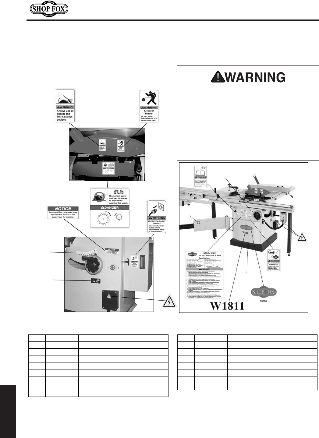
-64-
N(/((('Jc`[`e^KXYc\JXn
G8IKJ
()
*
+
,
-.
/
0
('
((
()
(*
(+
(,
(-
(.
G8IKJ
CXY\cj:fjd\k`Zj
REF PART # DESCRIPTION REF PART # DESCRIPTION
1 X18110001 TABLE SAW BLADE GUARD LABEL 10 D3376 SHOP FOX NAMEPLATE
2 X18110002 KICKBACK HAZARD LABEL 11 X18110011 MODEL # LABEL (W1811)
3 X18110003 QUALIFIED PERSONNEL LABEL 12 X18110012 MACHINE ID LABEL (W1811)
4 X18110004 BLADE GUARD DANGER LABEL 13 XLABEL-04 ELECTRICITY LABEL
5 X18110005 DISCONNECT POWER LABEL 14 X18110014 BLADE ELEVATION LABEL
6 XLABEL-12 READ MANUAL LABEL 15 X18110015 BLADE TILT SCALE
7 X18110007 BLADE TILT LABEL 16 XPPAINT-1 WHITE TOUCH-UP PAINT
8 XLABEL-04S ELECTRICITY LABEL 17 XPPAINT-7 BLACK TOUCH-UP PAINT
9 XLABEL-06 GLASSES/RESPIRATOR LABEL
JX]\kpcXY\cjnXieXYflkdXZ_`e\_XqXi[jXe[
_fn kf gi\m\ek dXZ_`e\ [XdX^\ fi `ealip%
K_\fne\if]k_`jdXZ_`e\DLJKdX`ekX`ek_\
fi`^`eXc cfZXk`fe Xe[ i\X[XY`c`kp f] Xcc cXY\cj
fe k_`j dXZ_`e\% @] Xep cXY\c `j i\dfm\[ fi
Y\Zfd\j lei\X[XYc\# I<GC8:< k_Xk cXY\c
Y\]fi\Xccfn`e^k_\dXZ_`e\kf\ek\ij\im`Z\
X^X`e% :fekXZk Nff[jkfZb @ek\ieXk`feXc# @eZ%
Xk (*-') .*+$*+/) fi nnn%j_fg]fokffcj%Zfd
kffi[\ie\ncXY\cj%
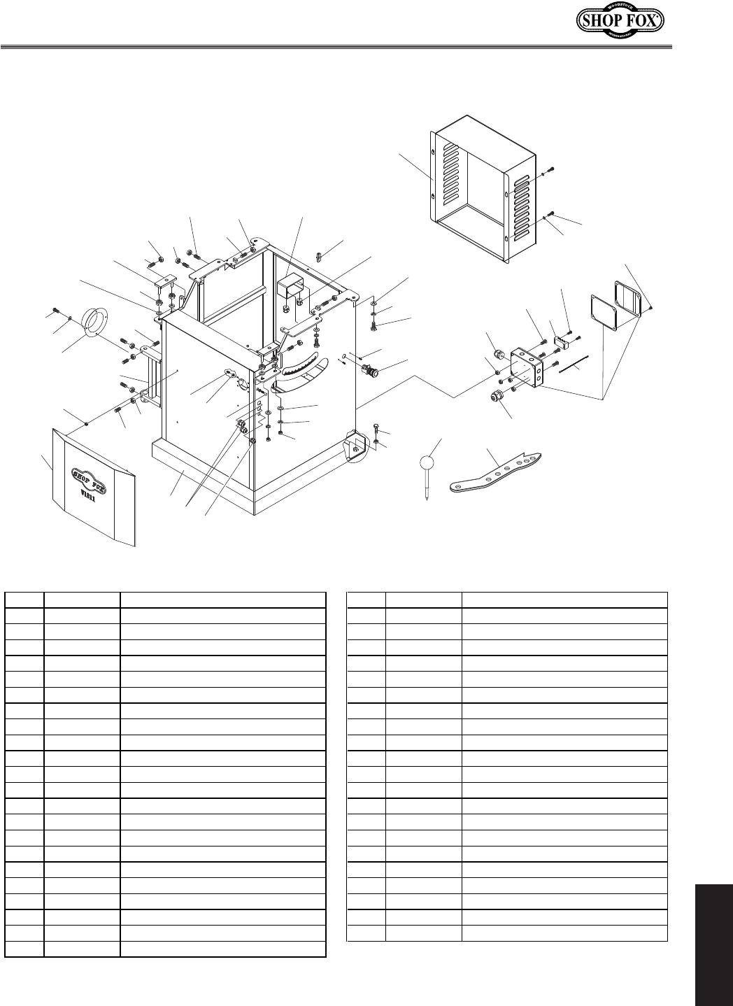
-65-
N(/((('Jc`[`e^KXYc\JXn
G8IKJ
:XY`e\k
(*+
(** (*)
(')
(*( (*.
(*/
(*0
(+*
(++
(+,
()0
(*'
('0
('0
('/
('+ ('*
(()
(()
(()
(*-
(*,
(+'
(+)
(),
(+(
(((
()'
()(
())
(('
('-
()-()+
(),
(), (+-
(+.
((0
((.
()/
((-
((*
((+
('(
('.
('.
((/
((,
()*
REF PART # DESCRIPTION REF PART # DESCRIPTION
101 X18110101 CABINET 125 XPWF10M FENDER WASHER 10MM
102 X18110102 COVER PLATE 126 XPLW06M LOCK WASHER 10MM
103 X18110103 EMERGENCY STOP BUTTON 128 X18110128 FRONT PANEL
104 XPHTEK19M TAP SCREW M5 X 16 129 XPSS74M SET SCREW M8-1.25 X 35
106 XPLW06M LOCK WASHER 10MM 130 XPN03M HEX NUT M8-1.25
107 XPN02M HEX NUT M10-1.5 131 XPN01M HEX NUT M6-1
108 X18110108 SWITCH BOX 132 XPSB11M CAP SCREW M8-1.25 X 16
109 X18110109 STRAIN RELIEF PG-9 133 XPW01M FLAT WASHER 8MM
110 XPSBS09M BUTTON HD CAP SCR M6-1 X 12 134 X18110134 WIRE CONNECTOR
111 XPN01M HEX NUT M6-1 135 X18110135 ARBOR LOCK TOOL
112 X18110112 STRAIN RELIEF PG13.5 136 X18110136 PUSH STICK
113 XPN02M HEX NUT M10-1.5 137 XPSS105M SET SCREW M12-1.75 X 35
114 XPSS84M SET SCREW M10-1.5 X 35 138 XPN03M HEX NUT M8-1.25
115 X18110115 DUST PORT 4" 139 X18110139 PLUG 10MM
116 XPLW03M LOCK WASHER 6MM 140 X18110140 GROUND RETURN WIRE
117 XPS11M PHLP HD SCR M6-1 X 16 141 XPB35M HEX BOLT M12-1.75 X 40
118 XPSS74M SET SCREW M8-1.25 X 35 142 XPN09M HEX NUT M12-1.75
119 XPN03M HEX NUT M8-1.25 143 X18110143 HINGE BRACKET
120 X18110120 POWER CONNECTION BOX 144 XPSS94M SET SCREW M10-1.5 X 25
121 X18110121 TERMINAL BLOCK 4-POST 145 XPSS01M SET SCREW M6-1 X 10
122 X18110122 PHLP HD SCR M3.5-.6 X 20 146 XPLN05M LOCK NUT M10-1.5
123 X18110123 BUTTON HD CAP SCR M5-.8 X 35 147 X18110147 S. TABLE MOUNTING PLATE
124 XPB01M HEX BOLT M10-1.5 X 30
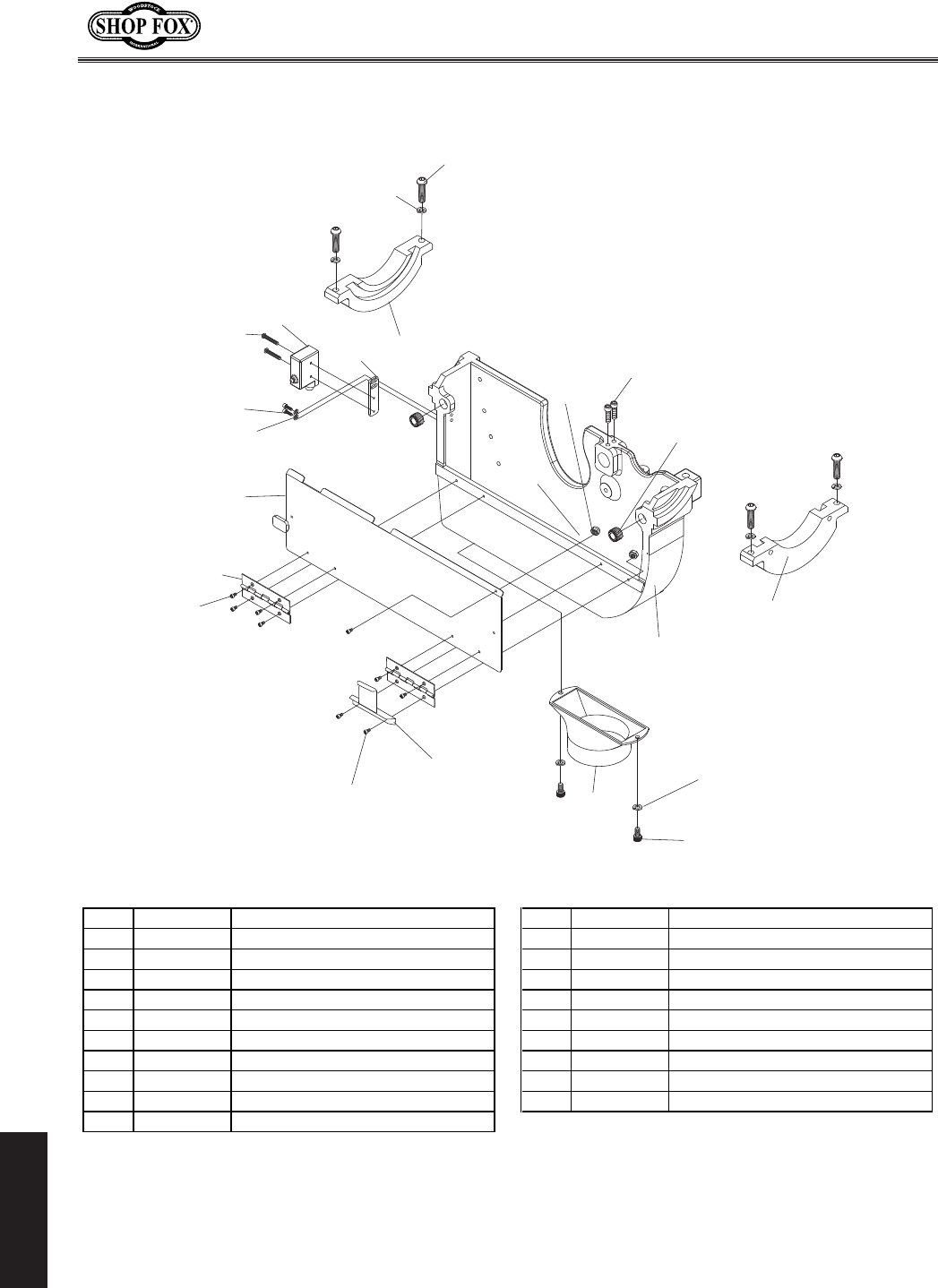
-66-
N(/((('Jc`[`e^KXYc\JXn
G8IKJ
Kilee`fe
)(0
)))
))(
))'
)'+
)(/
)(.
)(,
)(+
)(*
)()
)((
)('
)'0
)'/
)'.
)'*
)')
)')
)'(
)',
)'-
REF PART # DESCRIPTION REF PART # DESCRIPTION
201 X18110201 CHANNEL BASE 212 XPLW01M LOCK WASHER 5MM
202 X18110202 TRUNNION BRACKET 213 X18110213 BLADE GUARD PLATE
203 XPSB04M CAP SCREW M6-1 X 10 214 X18110214 HINGE
204 XPLW03M LOCK WASHER 6MM 215 XPS09M PHLP HD SCR M5-.8 X 10
205 XPSB11M CAP SCREW M8-1.25 X 16 217 X18110217 MAGNET ASSEMBLY
206 XPSBS04M BUTTON HD CAP SCR M8-1.25 X 35 218 X18110218 BLADE SHROUD DUST PORT
207 XPLW04M LOCK WASHER 8MM 219 XPS22M PHLP HD SCR M5-.8 X 25
208 X18110208 STOP BRACKET 220 XPLN02M LOCK NUT M5-.8
209 X18110209 LIMIT SWITCH AZZ7100 221 XPLW01M LOCK WASHER 5MM
210 XPS18M PHLP HD SCR M4-.7 X 25 222 X18110222 KEEPER PLATE
211 XPSB50M CAP SCREW M5-.8 X 10
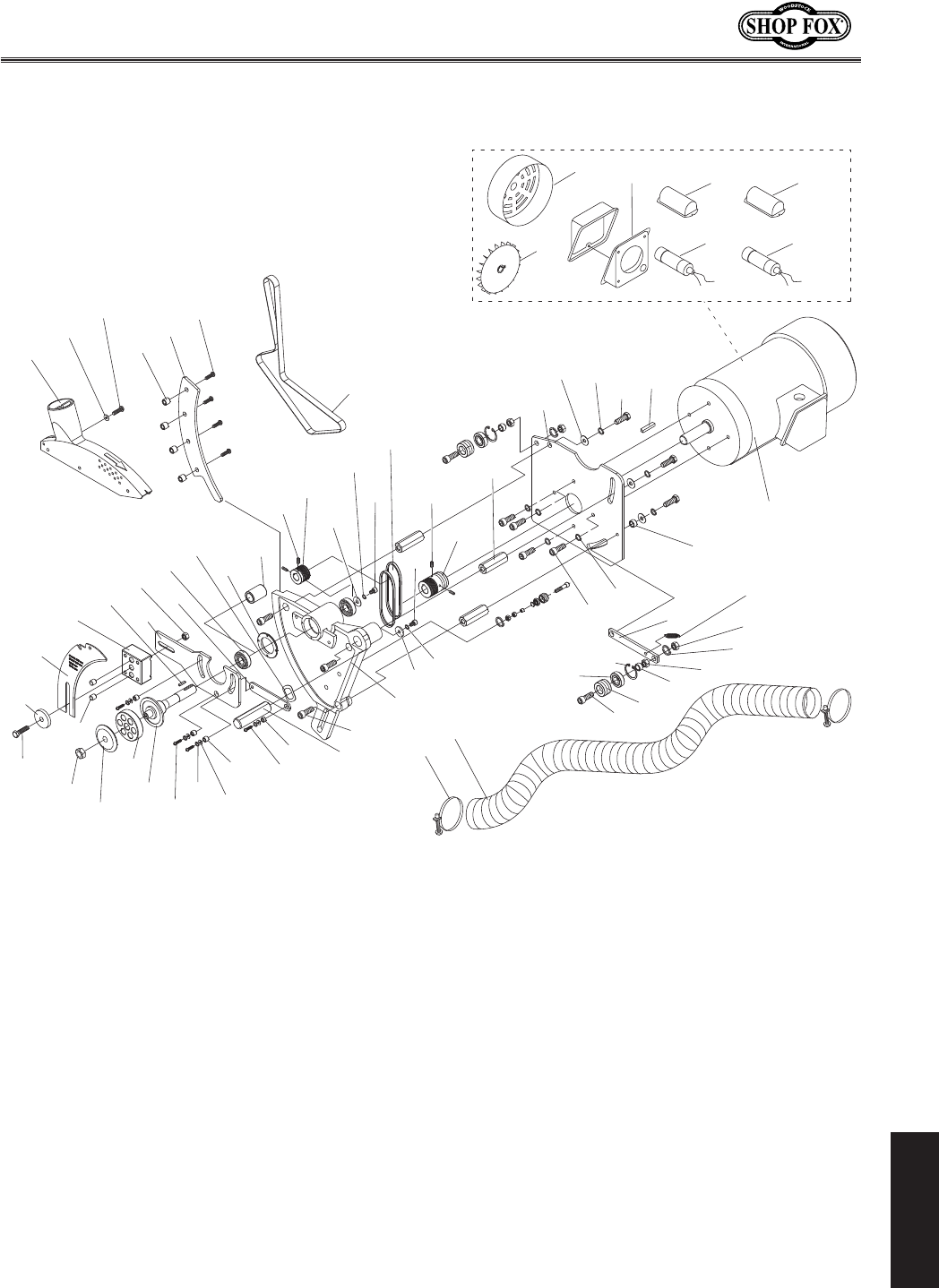
-67-
N(/((('Jc`[`e^KXYc\JXn
G8IKJ
DX`eDfkfi
*-.
*,-
*-+
*-*
*-)
*-'
*--
*,/
*,.
*-,
*,,
*,0
*,*
*,)
*-(
*('
*+(
*+,
*++
**)
**(
**'
*)0
*).
*)/
*)-
*),
*)+
*)(
*)*
*))
*)'
*(0
*(/
*(.
*(-
*(,
*(*
*()
*'/
*'0
*'.
*',
*'*
*')
*+0
***
*(+
*((
*'-
*,(
*'+
*,'
**+
**,
**-
**.
**/
**0
*+'
*+)
*+*
*+-
*+.
*+/
*'(
*)/$)
*)/$( *)/$+
*)/$,
*)/$* *)/$-
*)/$.

-68-
N(/((('Jc`[`e^KXYc\JXn
G8IKJ
REF PART # DESCRIPTION REF PART # DESCRIPTION
301 X18110301 BLADE GUARD 331 XPSB14M CAP SCREW M8-1.25 X 20
302 XPWF08M FENDER WASHER 8MM 332 XPLW04M LOCK WASHER 8MM
303 XPSBS07M BUTTON HD CAP SCR M8-1.25 X 40 333 XPWF08M FENDER WASHER 8MM
304 X18110304 RIVING KNIFE MOUNTING BLOCK 334 X18110334 ROTATE PLATE
305 XPK34M KEY 5 X 5 X 20 335 XPSB77M CAP SCREW M12-1.75 X 30
306 X18110306 LOCATING BLOCK 336 X18110336 SHAFT
307 XPN09M HEX NUT M12-1.75 337 X18110337 BUSHING
308 X18110308 LINK PLATE 338 XPSBS22M BUTTON HD CAP SCR M8-1.25 X 20
309 XP60042RS BALL BEARING 6004-2RS 339 X18110339 BUSHING
310 X18110310 WAVE WASHER 26 X 34MM 340 XPWF08M FENDER WASHER 8MM
311 X18110311 COLLAR 341 XPLW04M LOCK WASHER 8MM
312 X18110312 GIB PLATE 342 XPSBS03M BUTTON HD CAP SCR M8-1.25 X 16
313 XPSBS08M BUTTON HD CAP SCR M10-1.5 X 35 343 X18110343 MAIN ARBOR CSA
314 XPSS03M SET SCREW M6-1 X 8 344 X18110344 ARBOR FLANGE CSA
315 X18110315 ARBOR PULLEY TYPE M 345 X18110345 LOCATING PIN
316 XPW01M FLAT WASHER 8MM 346 XPB73M HEX BOLT M10-1.5 X 50
317 XPLW04M LOCK WASHER 8MM 347 X18110347 RIVING KNIFE WASHER 10MM
318 XPVM20 V-BELT M-20 3L200 348 X18110348 RIVING KNIFE
319 XPSB14M CAP SCREW M8-1.25 X 20 349 X18110349 SPECIAL ARBOR WASHER
320 XPSS02M SET SCREW M6-1 X 6 350 X18110350 HOSE 3" X 60CM
321 X18110321 MOTOR PULLEY TYPE M 351 X18110351 HOSE CLAMP 3-1/4"
322 X18110322 SHAFT 352 XPSB119M CAP SCREW M12-1.75 X 55
323 X18110323 MAIN MOTOR MOUNTING PLATE 353 X18110353 IDLER PULLEY
324 XPW06M FLAT WASHER 12MM 355 XPN09M HEX NUT M12-1.75
325 XPLW05M LOCK WASHER 12MM 356 XPN09M HEX NUT M12-1.75
326 XPB25M HEX BOLT M12-1.75 X 25 357 X18110357 ROTATE PLATE
327 XPK61M KEY 7 X 7 X 30 358 XPR20M INT RETAINING RING 28MM
328 X18110328 MOTOR 5HP 220V 1-PH 359 X18110359 BUSHING
328-1 X18110328-1 MOTOR FAN COVER 360 X18110360 BELT 15 X 1140
328-2 X18110328-2 MOTOR FAN 361 X18110361 PLATE
328-3 X18110328-3 JUNCTION BOX 362 X18110362 BUSHING
328-4 X18110328-4 CAPACITOR COVER 363 X18110363 ARBOR NUT 5/8"
328-5 X18110328-5 S CAPACITOR 400M 250V 1-3/4 X 3-1/2 364 X18110364 BUSHING
328-6 X18110328-6 CAPACITOR COVER 365 XPLW05M LOCK WASHER 12MM
328-7 X18110328-7 R CAPACITOR 30M 500V 1-1/2 X 3-3/8 366 XP6001 BALL BEARING 6001ZZ
329 XPSB14M CAP SCREW M8-1.25 X 20 367 X18110367 EXTENSION SPRING
330 XPLW04M LOCK WASHER 8MM
DX`eDfkfi
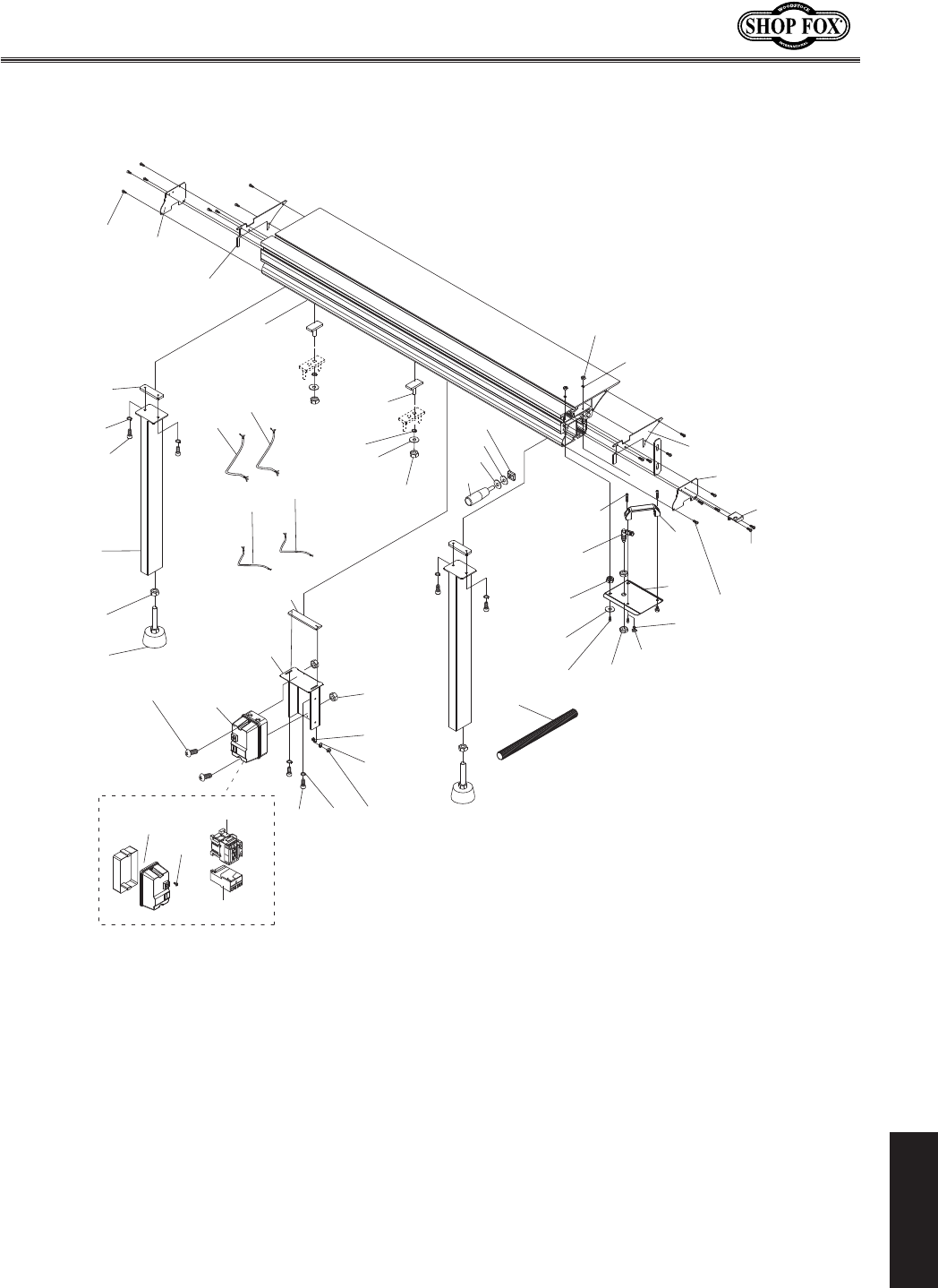
-69-
N(/((('Jc`[`e^KXYc\JXn
G8IKJ
Sliding Table
+'-
+'(
+')
+'*
+'+
+',
+'.
+'/
+'0
+('
+((
+(/ +(0
+)'
+()
+(-
+(,
+,(
+'*
+,)
+,*
+*.
+(*
+(+
+))
+)*
+)+
+),
+)-
+).
+)0
+)/
+*(
++.
++/
++0 +,'
+*' +**
+*0
+*)
+(.
+*/
++'
+*+
++(
++*
++)
+++
++,
+)0$*
+)0$)
+)0$(
+)0$+

-70-
N(/((('Jc`[`e^KXYc\JXn
G8IKJ
Sliding Table Parts List
REF PART # DESCRIPTION REF PART # DESCRIPTION
401 X18110401 SLIDING TABLE SET 688x316 429 X18110429 SWITCH MP-18 5HP 220V 1PH
402 X18110402 S. TABLE T-STUD M12-1.75 X 35 429-1 X18110429-1 SWITCH BOX
403 XPW06M FLAT WASHER 12MM 429-2 X18110429-2 CONTACTOR SDE MA-18 220V
404 XPLW05M LOCK WASHER 12MM 429-3 X18110429-3 RELAY SDE RA-30 22-34 25A
405 XPN09M HEX NUT M12-1.75 429-4 XPSW01-1 SWITCH COVER SCREW WHITE
406 XPLW03M LOCK WASHER 6MM 430 XPS56M PHLP HD SCR M4-.7 X 16
407 XPN01M HEX NUT M6-1 431 XPSB33M CAP SCREW M5-.8 X 12
408 XPN13M HEX NUT M16-2 432 X18110432 SWITCH T-SLOT PLATE
409 XPSBS11M BUTTON HD CAP SCR M6-1 X 10 433 XPN06M HEX NUT M5-.8
410 XPSBS11M BUTTON HD CAP SCR M6-1 X 10 434 XPW02M FLAT WASHER 5MM
411 X18110411 LOCK RECEIVER PLATE 437 XPFN02M FLANGE NUT M6-1
412 X18110412 S. TABLE END PLATE UPPER 438 XPSB33M CAP SCREW M5-.8 X 12
413 X18110413 HANDLE 439 XPW02M FLAT WASHER 5MM
414 X18110414 S. TABLE HANDLE PLATE 440 XPN06M HEX NUT M5-.8
415 XPSB01M CAP SCREW M6-1 X 16 441 XPW03M FLAT WASHER 6MM
416 X18110416 PIN LOCK 442 XPLW03M LOCK WASHER 6MM
417 XPSB115M BUTTON HD CAP SCR M6-1 X 16 443 XPN01M HEX NUT M6-1
418 XPSBS11M BUTTON HD CAP SCR M6-1 X 10 444 X18110444 FLEXIBLE CONDUIT
419 X18110419 S. TABLE END PLATE LL 445 X18110412 S. TABLE END PLATE UPPER
420 X18110420 S. TABLE END PLATE LR 447 X18110447 MOTOR CORD 3C 12AWG
422 X18110422 SUPPORT LEG T-SLOT PLATE 448 X18110448 PWR BOX CORD 3C 12AWG
423 XPLW04M LOCK WASHER 8MM 449 X18110449 LIMIT SWITCH CORD 2C 18AWG
424 XPSB14M CAP SCREW M8-1.25 X 20 450 X18110450 E-STOP CORD 2C 18AWG
425 X18110425 S. TABLE SUPPORT LEG 451 X18110451 PUSH HANDLE M12-1.75 X 14
426 XPN09M HEX NUT M12-1.75 452 X18110452 PLASTIC WASHER 12MM
427 X18110427 FOOT 453 X18110453 PUSH HANDLE T-NUT M12-1.75
428 X18110428 SWITCH MOUNTING BRACKET
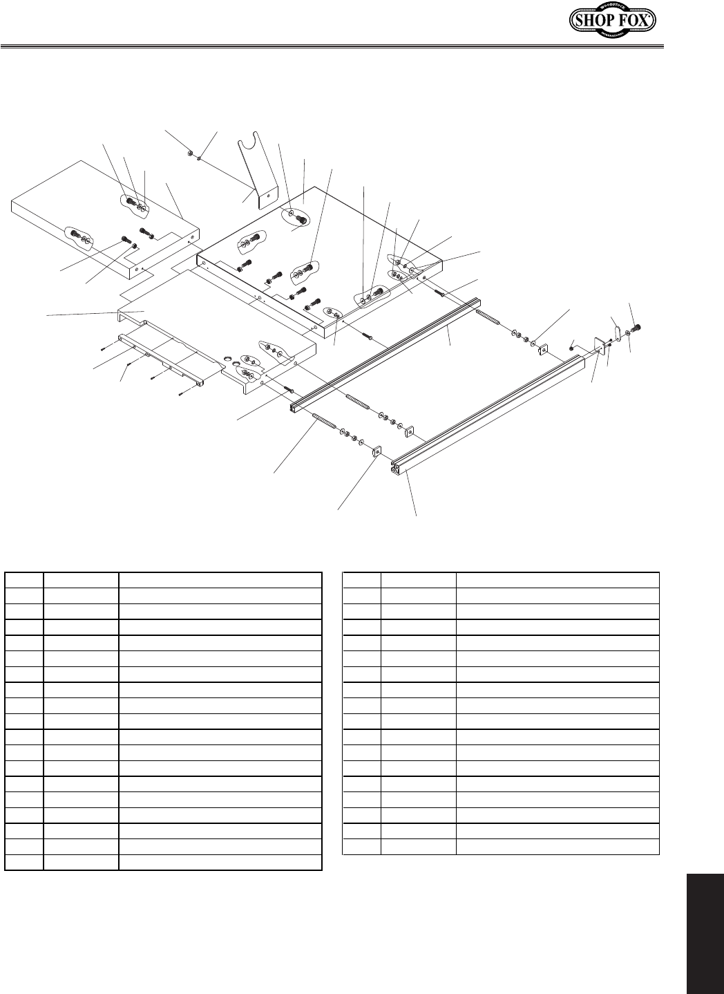
-71-
N(/((('Jc`[`e^KXYc\JXn
G8IKJ
,*.
,'0
,*,
,*+
,((
,*-
,**
,*'
,)0
,*(
,',
,('
,*)
,)/
,).
,)-
,(0
,),
,)+
,)*
,)'
,)(
,)) ,(.
,(/
,(-
,(,
,(+
,(*
,'/
,'.
,'-
,'+
,')
,'*
,()
,'(
KXYc\j
REF PART # DESCRIPTION REF PART # DESCRIPTION
501 X18110501 LARGE EXTENSION TABLE 520 XPHTEK15M TAP SCREW M4 X 10
502 X18110502 CAST IRON TABLE 521 X18110521 RAIL END PLATE
503 X18110503 TABLE INSERT 522 X18110522 SMALL EXTENSION TABLE
504 XPSB15M CAP SCREW M5-.8 X 20 523 XPW04M FLAT WASHER 10MM
505 X18110505 RIP FENCE SCALE 524 XPLW06M LOCK WASHER 10MM
506 X18110506 STUD M12-1.75 X 90 525 XPSB64M CAP SCREW M10-1.5 X 25
507 X18110507 T-NUT M12-1.75 526 XPLW01M LOCK WASHER 5MM
508 X18110508 RIP FENCE RAIL 527 XPSBS06M BUTTON HD CAP SCR M5-.8 X 12
509 XPB10M HEX BOLT M6-1 X 25 528 X18110528 STOP TAB
510 XPLW03M LOCK WASHER 6MM 529 XPSB64M CAP SCREW M10-1.5 X 25
511 XPN01M HEX NUT M6-1 530 X18110530 HOSE SUPPORT
512 XPW06M FLAT WASHER 12MM 531 XPLW06M LOCK WASHER 10MM
513 XPW06M FLAT WASHER 12MM 532 XPLN05M LOCK NUT M10-1.5
514 XPLW05M LOCK WASHER 12MM 533 XPW04M FLAT WASHER 10MM
515 XPN09M HEX NUT M12-1.75 534 XPN03M HEX NUT M8-1.25
516 XPLW06M LOCK WASHER 10MM 535 XPSB31M CAP SCREW M8-1.25 X 25
517 XPW04M FLAT WASHER 10MM 536 XPB83M HEX BOLT M6-1 X 16
518 XPSB64M CAP SCREW M10-1.5 X 25 537 XPW03M FLAT WASHER 6MM
519 XPLN02M LOCK NUT M5-.8
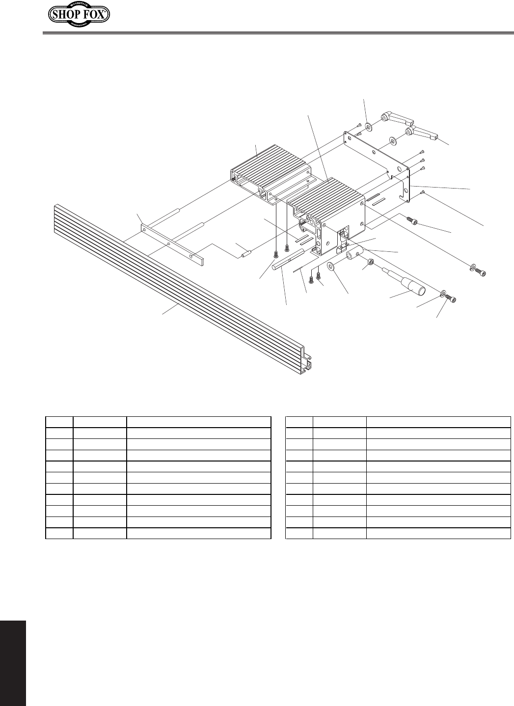
-72-
N(/((('Jc`[`e^KXYc\JXn
G8IKJ
I`g=\eZ\
-))
-(.
-((
-)(
-)'
-(0
-(/
-(,
-(- -(*
-()
-'.
-'-
-',
-'(
-(+
-'* -('
-'0
-'/
-'+
-')
REF PART # DESCRIPTION REF PART # DESCRIPTION
601 X18110601 RIP FENCE 612 XPHTEK4M TAP SCREW M4 X 8
602 X18110602 CLAMP PLATE 613 X18110613 LOCK PLATE HANDLE M8-1.25
603 X18110603 STEEL PIN 6MM 614 XPW01M FLAT WASHER 8MM
604 X18110604 ROD 615 X18110615 RIP FENCE FRONT BASE
605 X18110605 HDPE STRIP 616 X18110616 RIP FENCE REAR BASE
606 XPFS07M FLANGE SCREW M5-.8 X 10 617 X18110617 PLASTIC SCREW M5-.8 X 16
607 XPN03M HEX NUT M8-1.25 618 XPLW04M LOCK WASHER 8MM
608 X18110608 FENCE LOCK HANDLE 619 XPSB14M CAP SCREW M8-1.25 X 20
609 X18110609 SLEEVE 620 XPFH02M FLAT HD SCR M6-1 X 12
610 X18110610 SPRING PRESSURE PLATE 621 X18110621 WAVY WASHER 12MM
611 X18110611 COVER PLATE 622 X18110622 HDPE STRIP 50 X 5MM
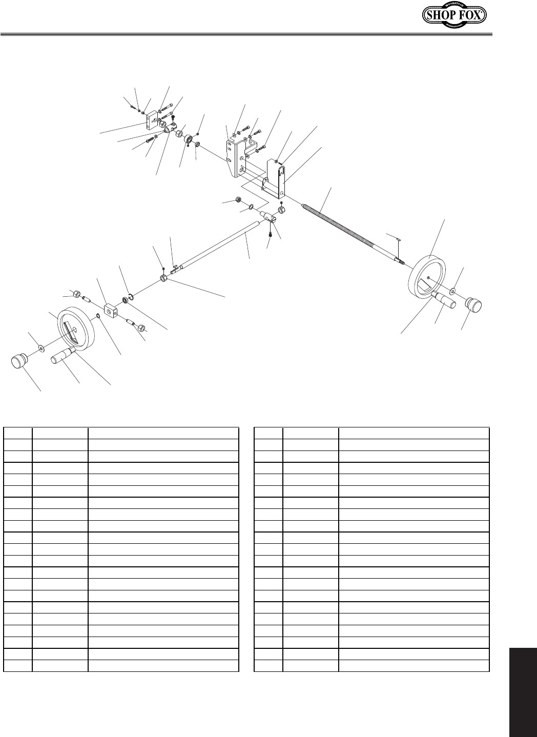
-73-
N(/((('Jc`[`e^KXYc\JXn
G8IKJ
?Xe[n_\\cj
.'/
.)+
.*+
.*/
.+'
.)0
.(0
.*0
.'*
.+(
.')
.+* .'(
.()
.(*
.(+
.(,
.(-
.(.
.(/
.)'
.)(
.))
.)*
.*)
.*(
.*'
.((
.)/
.+)
.).
.)-
.*-
.*.
.**
.'.
.'-
.',
.'+
.'*
.+(
.'0
.('
.),
.'( .') .+*
REF PART # DESCRIPTION REF PART # DESCRIPTION
701 X18110701 LOCK KNOB M10-1.5 722 X18110722 BEARING SELF LUBRICATING
702 X18110702 HANDWHEEL HANDLE 723 XPW03M FLAT WASHER 6MM
703 X18110703 HANDWHEEL 724 XPR03M EXT RETAINING RING 12MM
704 XPK34M KEY 5 X 5 X 20 725 X18110725 LOCATE BLOCK
705 X18110705 ANGLE SEAT 726 X18110726 LOCATE SHAFT
706 XPR20M INT RETAINING RING 28MM 727 XPSB04M CAP SCREW M6-1 X 10
707 XPSS02M SET SCREW M6-1 X 6 728 XPW03M FLAT WASHER 6MM
708 XPSB61M CAP SCREW M10-1.5 X 20 729 X18110729 SLEEVE
709 X18110709 LEADSCREW M16 X 2P X 2T 730 XPLN07M LOCK NUT M16-2
710 X18110710 NUT 731 X18110731 COPPER WASHER 16MM
711 X18110711 LOCATE RING 732 XPSB26M CAP SCREW M6-1 X 12
712 X18110712 LEADSCREW M16 X 2P X 2T 733 X18110733 LOCKING SHAFT NUT M16-2
713 X18110713 FINGER GUIDE 734 XPN09M HEX NUT M12-1.75
714 XPSB04M CAP SCREW M6-1 X 10 736 XPK34M KEY 5 X 5 X 20
715 XPLW03M LOCK WASHER 6MM 737 X18110737 BEARING
716 XPSB14M CAP SCREW M8-1.25 X 20 738 XPSS105M SET SCREW M12-1.75 X 35
717 XPLW04M LOCK WASHER 8MM 739 XPSS02M SET SCREW M6-1 X 6
718 XPW01M FLAT WASHER 8MM 740 XPN13M HEX NUT M16-2
719 X18110719 STRUT BOARD 741 X18110741 DISC WASHER 10 X 20
720 XPSB05M CAP SCREW M8-1.25 X 50 742 X18110742 BUSHING
721 XPLW04M LOCK WASHER 8MM 743 X18110743 HANDLE EXTENSION
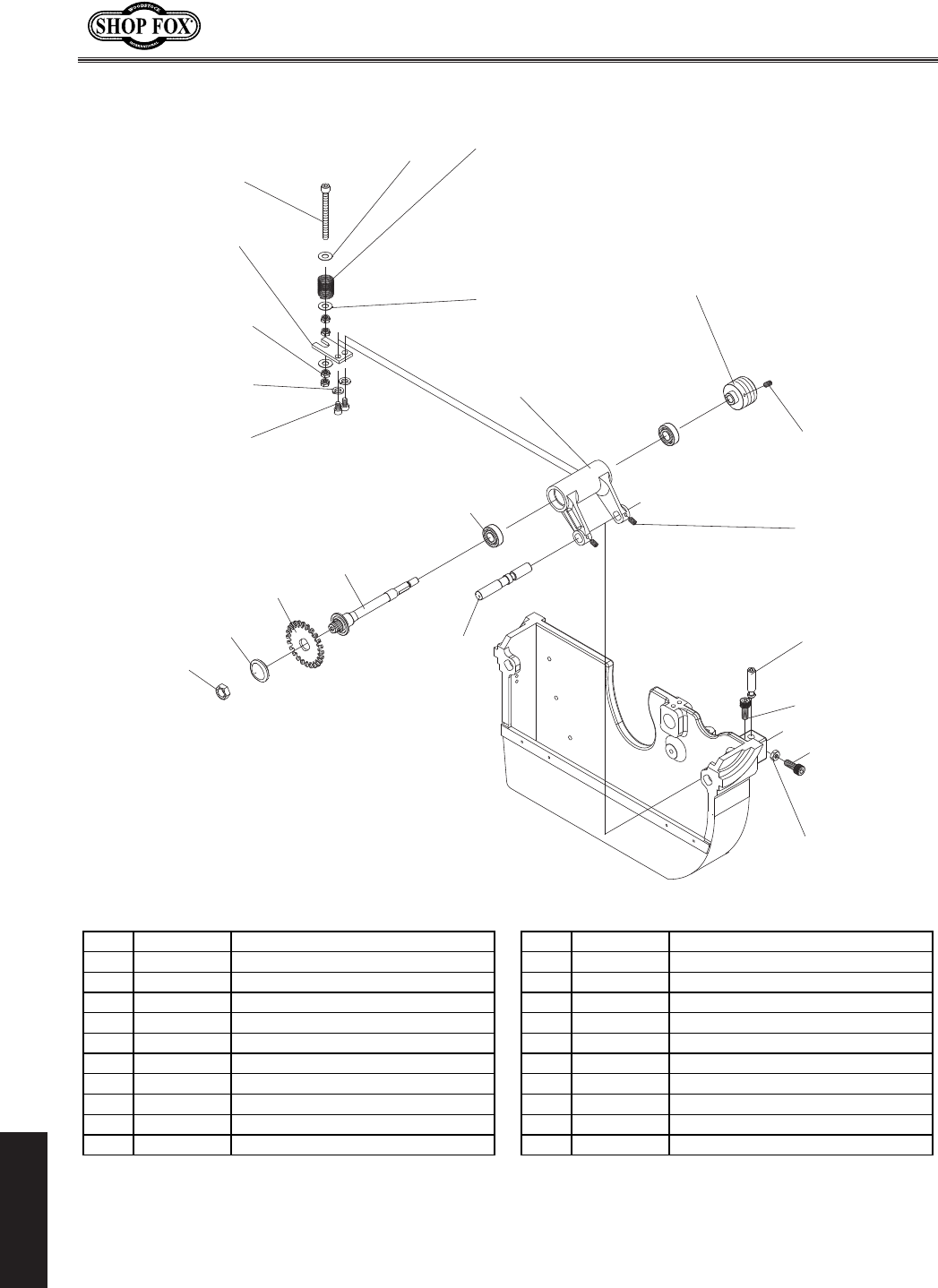
-74-
N(/((('Jc`[`e^KXYc\JXn
G8IKJ
JZfi`e^Kilee`fe
/)(
/))
/'(
/)'
/(0
/'*
/(-
/(.
/(/
/(,
/((
/('
/'0
/(+
/(*
/()
/'.
/',
/'/
/'-
/'+
/')
REF PART # DESCRIPTION REF PART # DESCRIPTION
801 X18110801 ARBOR FLANGE 812 X18110812 ADJUST SCREW M8-1.25 X 100
802 X18110802 SCORING SAW BLADE CSA 22MM 813 X18110813 PLATE
803 XPSB14M CAP SCREW M8-1.25 X 20 814 XPLW04M LOCK WASHER 8MM
804 X18110804 SHAFT CSA 22MM 815 XPSB31M CAP SCREW M8-1.25 X 25
805 X18110805 SHAFT 816 X18110816 COMPRESSION SPRING
806 X18110806 SCORING ARBOR BEARING 817 XPLN04M LOCK NUT M8-1.25
807 X18110807 REGULATOR 818 XPW01M FLAT WASHER 8MM
808 X18110808 SCORING PULLEY 60HZ 819 X18110819 SCORING ARBOR NUT
809 XPSS02M SET SCREW M6-1 X 6 820 XPW01M FLAT WASHER 8MM
810 XPSS02M SET SCREW M6-1 X 6 821 XPSB02M CAP SCREW M6-1 X 20
811 X18110811 ADJUST SHAFT 822 XPN01M HEX NUT M6-1
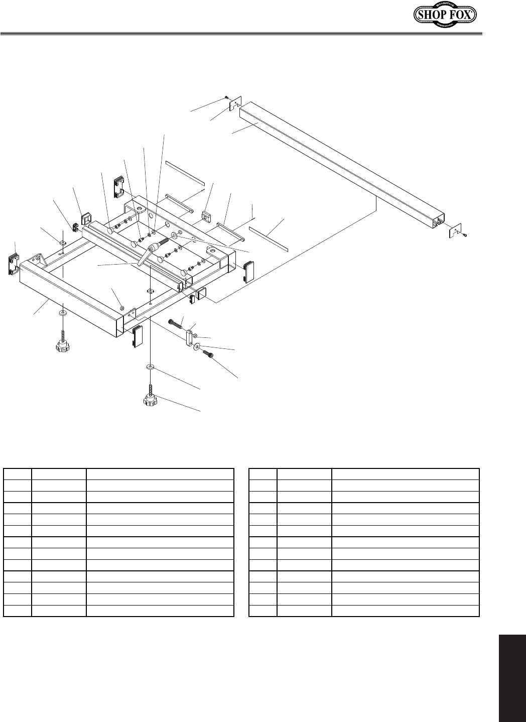
-75-
N(/((('Jc`[`e^KXYc\JXn
G8IKJ
:ifjjZlkKXYc\
0)-
0((
0(*
0),
0()
0(,
0'(
0(/
0(0
0(.
0',
0'+
0'-
0)'
0)(
0(-
0'.
0'/
0(+
0'*
0')
0)*
0))
0)+
0('
0'0
REF PART # DESCRIPTION REF PART # DESCRIPTION
901 X18110901 CROSSCUT TABLE 914 XPW03M FLAT WASHER 6MM
902 X18110902 PLUG 38 X 38 915 X18110915 PLUG 80 X 40
903 X18110903 PLUG 40 X 20 916 X18110916 PLUG
904 X18110904 T-NUT M12-1.75 917 X18110917 PIN 3 X 14
905 X18110905 T-SLOT BAR 918 X18110918 CC BRACE KNOB M8-1.25 X 50
906 X18110906 PAD 919 XPWF08M FENDER WASHER 8MM
907 XPSB115M BUTTON HD CAP SCR M6-1 X 16 920 X18110920 SUPPORT BAR
908 XPLW03M LOCK WASHER 6MM 921 X18110921 COVER
909 XPWF12M FENDER WASHER 12MM 922 X18110922 TAP SCREW #8 X 3/8"
910 X18110910 LOCK LEVER M12-1.75 X 55 923 X18110923 T-NUT M8-1.25
911 X18110911 FENCE STOP BLOCK 924 XPSB13M CAP SCREW M8-1.25 X 30
912 XPN03M HEX NUT M8-1.25 925 XPWF08M FENDER WASHER 8MM
913 XPB15M HEX BOLT M8-1.25 X 40 926 XPLN04M LOCK NUT M8-1.25
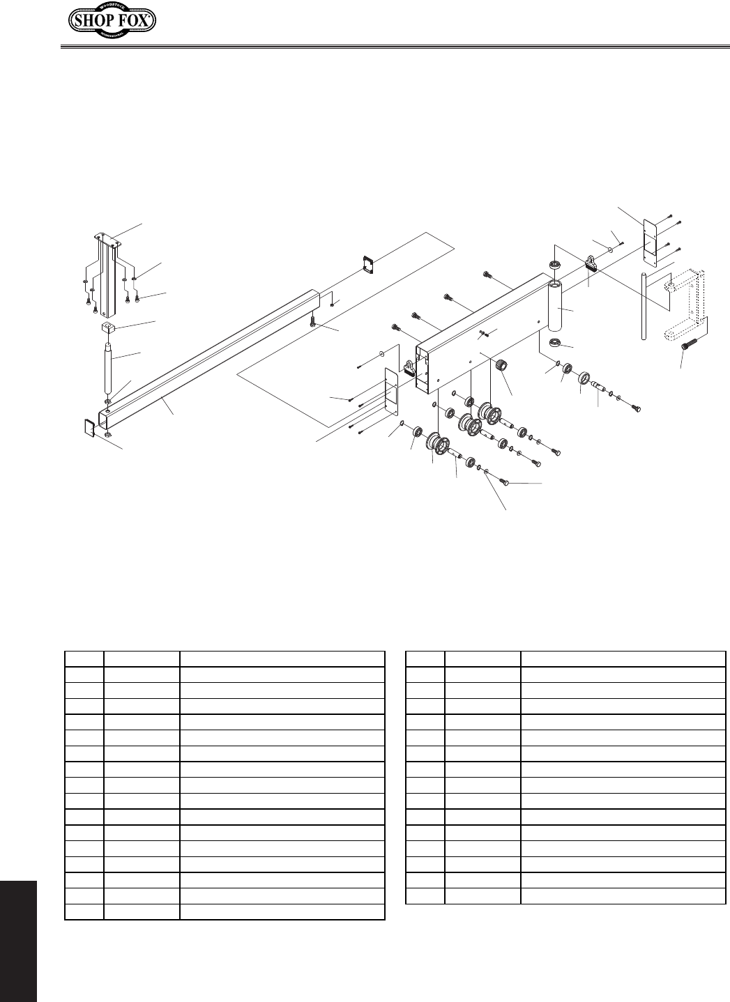
-76-
N(/((('Jc`[`e^KXYc\JXn
G8IKJ
Jn`e^8id
('**
('*+
(''-
('*)
(''+
(')0
('',
('),
(')+
(')*
('))
('(0
('(/
('(.
('(-
('*-
('*.
('*,
('(,
('(+
('(*
('()
(')(
(')'
('((
(''.
(''*
('')
(''(
('*'
(''/
(''0
('('
REF PART # DESCRIPTION REF PART # DESCRIPTION
1001 X18111001 CROSSCUT TABLE SUPPORT LEG 1018 X18111018 RING
1002 XPLW03M LOCK WASHER 6MM 1019 X18111019 ADJUST SHAFT
1003 XPSB01M CAP SCREW M6-1 X 16 1020 X18111020 HINGE SHAFT
1004 X18111004 ROTARY SHAFT 1021 XP6202 BALL BEARING 6202ZZ
1005 XPN28M HEX NUT M20-2.5 1022 X18111022 SWING ARM
1006 X18111006 PLUG 40 X 80 1023 X18111023 BRUSH
1007 X18111007 SLIDING TUBE 1024 XPW03M FLAT WASHER 6MM
1008 XPB26M HEX BOLT M8-1.25 X 30 1025 XPSB02M CAP SCREW M6-1 X 20
1009 XPN03M HEX NUT M8-1.25 1029 XPB14M HEX BOLT M10-1.5 X 35
1010 XPHTEK15M TAP SCREW M4 X 10 1030 X18111030 PLUG
1011 X18111011 COVER 1032 X18111032 COVER
1012 XPR05M EXT RETAINING RING 15MM 1033 XPB09M HEX BOLT M8-1.25 X 20
1013 XP6202 BALL BEARING 6202ZZ 1034 XPW01M FLAT WASHER 8MM
1014 X18111014 ROLLER 1035 X18111035 MAGNET BASE ASSEMBLY
1015 X18111015 ADJUST SHAFT 1036 XPN03M HEX NUT M8-1.25
1016 XPR05M EXT RETAINING RING 15MM 1037 XPSS21M SET SCREW M8-1.25 X 25
1017 XP6202 BALL BEARING 6202ZZ
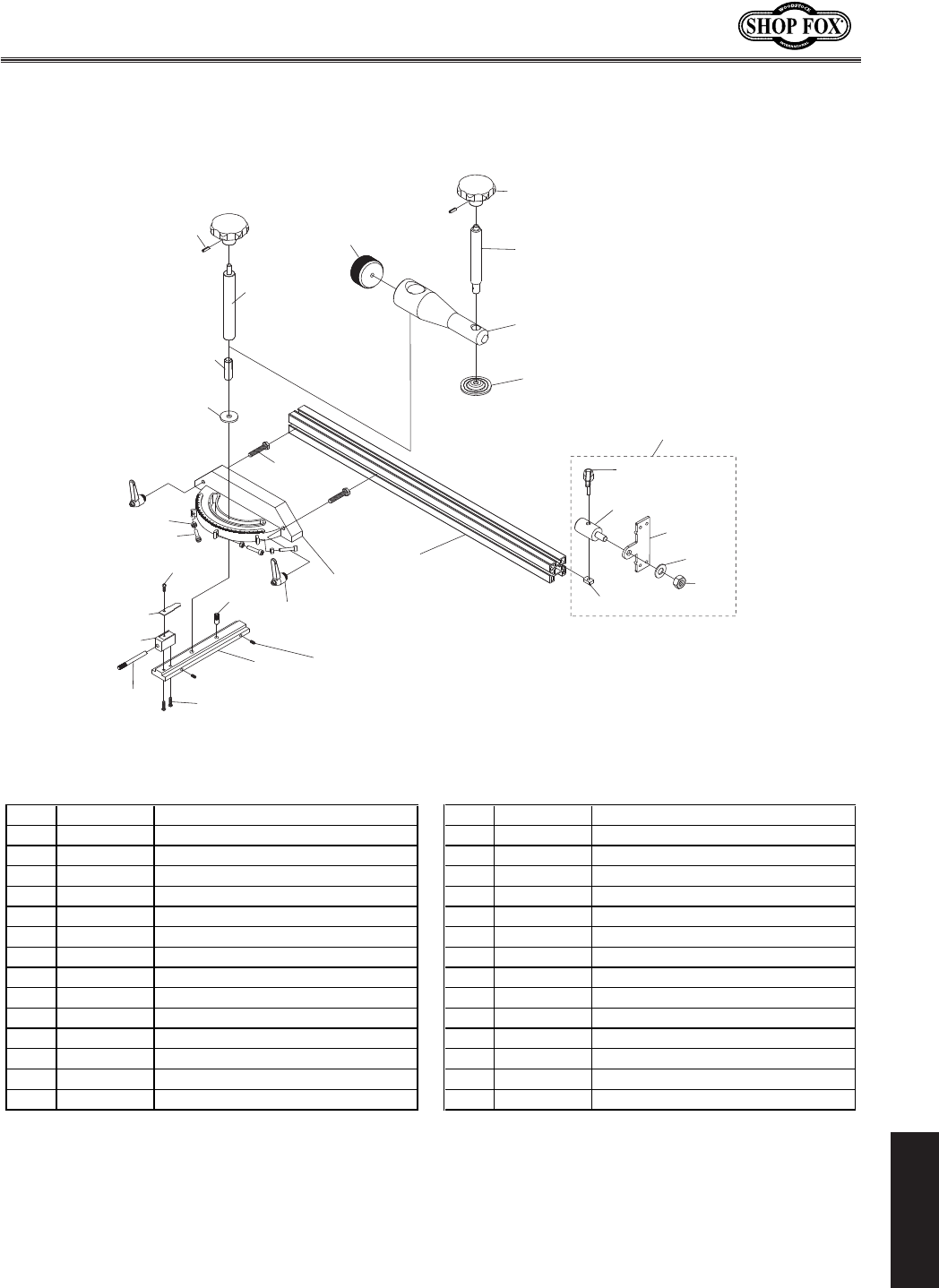
-77-
N(/((('Jc`[`e^KXYc\JXn
G8IKJ
D`k\i>Xl^\
(()0
(()/
(()(
(((,
(((.
(().
((),
(()+
(()*
(())
(()-
((')
(('( (((-
(((+
(((+8
(((*
((()
(()'
(((0
(((/
((((
((('
(('0
(('/
(('+
((',
(('*
(('.
(('-
REF PART # DESCRIPTION REF PART # DESCRIPTION
1101 X18111101 MITER GAUGE FENCE 1115 XPSN02M SQUARE NUT M6-1
1102 X18111102 MITER GAUGE BODY 1116 XPW04M FLAT WASHER 10MM
1103 X18111103 LARGE WASHER 1117 XPLN05M LOCK NUT M10-1.5
1104 X18111104 SLIDING MITER CLAMP SHAFT 1118 XPSB38M CAP SCREW M5-.8 X 25
1105 X18111105 CLAMP SHAFT 1119 XPS02M PHLP HD SCR M4-.7 X 12
1106 X18111106 KNOB PINNED 1120 X18111120 POINTER
1107 X18111107 KNURLED KNOB 1121 X18111121 FIXED BLOCK
1108 X18111108 MITER HANDLE SHAFT 1122 X18111122 STOP BAR
1109 XPWF08M FENDER WASHER 8MM 1123 XPS56M PHLP HD SCR M4-.7 X 16
1110 XPB29M HEX BOLT M6-1 X 30 1124 X18111124 MITER GUIDE BAR
1111 XPN06M HEX NUT M5-.8 1125 XPSS23M SET SCREW M4-.7 X 10
1112 X18111112 ADJUST HANDLE M6 X 30 1126 X18111126 ADJUST HANDLE
1113 X18111113 LOCK SHAFT 1127 X18111127 SHAFT
1114 X18111114 MITER FLIP STOP 1128 XPSS101M SET SCREW M8-1.25 X 45
1114A X18111114A MITER FLIP STOP ASSEMBLY 1129 XPRP42M ROLL PIN 3 X 20
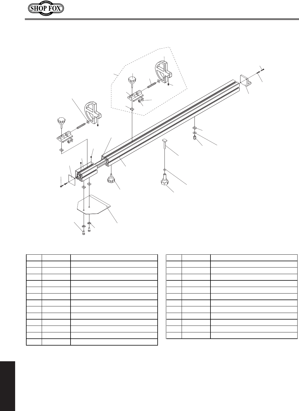
-78-
N(/((('Jc`[`e^KXYc\JXn
G8IKJ
:ifjjZlk=\eZ\
())-
())+
()),
()'/
())) ()))
()(/
()'(
())(
())'
()(0
()'(
()(.
()(-
()(,
()(+
()(*
()()
())*
()'0
()('
()((
()'.
()'-
()')
()'*
()'+
()',
()',8
REF PART # DESCRIPTION REF PART # DESCRIPTION
1201 X18111201 T-NUT M8-1.25 1214 X18111214 LOCATE PLATE
1202 X18111202 STOP BRACKET 1215 X18111215 CC FENCE LOCK KNOB M8-1.25 X 25
1203 X18111203 KNOB M8-1.25 X 40 1216 X18111216 SQUARE FENCE
1204 X18111204 SPECIAL SCREW 1217 X18111217 PIVOT STUD
1205 X18111205 FLIP STOP 1218 X18111218 FIBER WASHER 10MM
1205A X18111205A FLIP STOP ASSEMBLY 1219 X18111219 ROTATE BLOCK
1206 XPSS01M SET SCREW M6-1 X 10 1220 XPS38M PHLP HD SCR M4-.7 X 10
1207 XPLN05M LOCK NUT M10-1.5 1221 XPS25M PHLP HD SCR M4-.7 X 35
1208 X18111208 SQUARE TUBE 1222 X18111222 FIBER WASHER 10MM
1209 X18111209 EXT FENCE 1223 XPSS02M SET SCREW M6-1 X 6
1210 X18111210 COVER 1224 X18111224 CROSSCUT FENCE KNOB M8-1.25 X 55
1211 XPHTEK15M TAP SCREW M4 X 10 1225 XPWF08M FENDER WASHER 8MM
1212 XPSBS03M BUTTON HD CAP SCR M8-1.25 X 16 1226 X18111226 T-BOLT M8-1.25 X 60
1213 XPLW04M LOCK WASHER 8MM

N(/((('Jc`[`e^KXYc\JXn
CUT ALONG DOTTED LINE
Name ___________________________________________________________________________________
Street __________________________________________________________________________________
City _________________________ State ___________________________Zip ________________________
Phone # ______________________ Email___________________________Invoice # ___________________
Model #_________Serial #______________Dealer Name__________________Purchase Date___________
NXiiXekpI\^`jkiXk`fe
K_\]fccfn`e^`e]fidXk`fe`j^`m\efeXmfclekXipYXj`j%@kn`ccY\lj\[]fidXib\k`e^gligfj\jkf_\cglj
[\m\cfgY\kk\igif[lZkjXe[j\im`Z\j%F]Zflij\#Xcc`e]fidXk`fe`jjki`ZkcpZfe]`[\ek`Xc%
(% How did you learn about us?
_____ Advertisement _____ Friend ____ Local Store
_____ Mail Order Catalog _____ Website ____ Other:
)% How long have you been a woodworker/metalworker?
_____ 0-2 Years _____ 2-8 Years ____ 8-20 Years _____ 20+ Years
*% How many of your machines or tools are Shop Fox?
_____ 0-2 _____ 3-5 ____ 6-9 _____ 10+
+% Do you think your machine represents a good value? _____ Yes ____ No
,% Would you recommend Shop Fox products to a friend? _____ Yes ____ No
-% What is your age group?
_____ 20-29 _____ 30-39 ____ 40-49
_____ 50-59 _____ 60-69 ____ 70+
.% What is your annual household income?
_____ $20,000-$29,000 _____ $30,000-$39,000 ____ $40,000-$49,000
_____ $50,000-$59,000 _____ $60,000-$69,000 ____ $70,000+
/% Which of the following magazines do you subscribe to?
0% Comments:VVVVVVVVVVVVVVVVVVVVVVVVVVVVVVVVVVVVVVVVVVVVVVVVVVVVVVVVVVVVVVVVVV
VVVVVVVVVVVVVVVVVVVVVVVVVVVVVVVVVVVVVVVVVVVVVVVVVVVVVVVVVVVVVVVVVVVVVVVVVVVVV
VVVVVVVVVVVVVVVVVVVVVVVVVVVVVVVVVVVVVVVVVVVVVVVVVVVVVVVVVVVVVVVVVVVVVVVVVVVVV
VVVVVVVVVVVVVVVVVVVVVVVVVVVVVVVVVVVVVVVVVVVVVVVVVVVVVVVVVVVVVVVVVVVVVVVVVVVVV
VVVVVVVVVVVVVVVVVVVVVVVVVVVVVVVVVVVVVVVVVVVVVVVVVVVVVVVVVVVVVVVVVVVVVVVVVVVVV
____ Cabinet Maker
____ Family Handyman
____ Hand Loader
____ Handy
____ Home Shop Machinist
____ Journal of Light Cont.
____ Live Steam
____ Model Airplane News
____ Modeltec
____ Old House Journal
____ Popular Mechanics
____ Popular Science
____ Popular Woodworking
____ Practical Homeowner
____ Precision Shooter
____ Projects in Metal
____ RC Modeler
____ Rifle
____ Shop Notes
____ Shotgun News
____ Today’s Homeowner
____ Wood
____ Wooden Boat
____ Woodshop News
____ Woodsmith
____ Woodwork
____ Woodworker West
____ Woodworker’s Journal
____ Other:

TAPE ALONG EDGES--PLEASE DO NOT STAPLE
FOLD ALONG DOTTED LINE
FOLD ALONG DOTTED LINE
NFF;JKF:B@EK<IE8K@FE8C@E:%
G%F%9FO)*'0
9<CC@E>?8D#N80/)).$)*'0
Place
Stamp
Here

N8II8EKP
Nff[jkfZb@ek\ieXk`feXc#@eZ%nXiiXekjXccJ_fg=fodXZ_`e\ipkfY\]i\\f][\]\Zkj]ifdnfibdXej_`g
Xe[dXk\i`Xcj]fiXg\i`f[f]knfp\Xij]ifdk_\[Xk\f]fi`^`eXcgliZ_Xj\Ypk_\fi`^`eXcfne\i%
K_`jnXiiXekp[f\jefkXggcpkf[\]\Zkj[l\[`i\Zkcpfi`e[`i\Zkcpkfd`jlj\#XYlj\#e\^c`^\eZ\fi
XZZ`[\ekj#cXZbf]dX`ek\eXeZ\#fii\`dYlij\d\ekf]k_`i[gXikp\og\ej\j`eZlii\[%
Nff[jkfZb@ek\ieXk`feXc#@eZ%n`cci\gX`ifii\gcXZ\#Xk`kj\og\ej\Xe[Xk`kjfgk`fe#k_\J_fg=fo
dXZ_`e\fidXZ_`e\gXik#n_`Z_`eefidXclj\_Xjgifm\ekfY\[\]\Zk`m\#gifm`[\[k_Xkk_\fi`^`eXc
fne\ii\kliejk_\gif[lZkgi\gX`[kfXJ_fg=fo]XZkfipj\im`Z\Z\ek\in`k_giff]f]k_\`igliZ_Xj\
f]k_\gif[lZkn`k_`eknfp\Xij#Xe[gifm`[\jNff[jkfZb@ek\ieXk`feXc#@eZ%i\XjfeXYc\fggfikle`kpkf
m\i`]pk_\Xcc\^\[[\]\Zkk_ifl^_`ejg\Zk`fe%@]`k`j[\k\id`e\[k_\i\`jef[\]\Zk#fik_Xkk_\[\]\Zk
i\jlck\[]ifdZXlj\jefkn`k_`ek_\jZfg\f]Nff[jkfZb@ek\ieXk`feXc@eZ%jnXiiXekp#k_\ek_\fi`^`eXc
fne\idljkY\Xik_\Zfjkf]jkfi`e^Xe[i\klie`e^k_\gif[lZk%
K_`j`jNff[jkfZb@ek\ieXk`feXc#@eZ%jjfc\ni`kk\enXiiXekpXe[XepXe[XccnXiiXek`\jk_XkdXp
Y\`dgc`\[YpcXn#`eZcl[`e^Xepd\iZ_XekXY`c`kpfi]`ke\jj#]fiXepgXik`ZlcXigligfj\#Xi\_\i\Yp
c`d`k\[kfk_\[liXk`fef]k_`jni`kk\enXiiXekp%N\[fefknXiiXekk_XkJ_fg=fodXZ_`e\ipZfdgc`\j
n`k_k_\gifm`j`fejf]XepcXnfiXZkj%@eef\m\ekj_XccNff[jkfZb@ek\ieXk`feXc#@eZ%jc`XY`c`kple[\i
k_`jnXiiXekp\oZ\\[k_\gliZ_Xj\gi`Z\gX`[]fik_\gif[lZk#Xe[Xepc\^XcXZk`fejYifl^_kX^X`ejk
Nff[jkfZb@ek\ieXk`feXc#@eZ%j_XccY\ki`\[`ek_\JkXk\f]NXj_`e^kfe#:flekpf]N_XkZfd%N\j_Xcc
`eef\m\ekY\c`XYc\]fi[\Xk_#`eali`\jkfg\ijfejfigifg\ikpfi]fi`eZ`[\ekXc#Zfek`e^\ek#jg\Z`Xcfi
Zfej\hl\ek`Xc[XdX^\jXi`j`e^]ifdk_\lj\f]fligif[lZkj%
<m\ip\]]fik_XjY\\edX[\kf\ejli\k_XkXccJ_fg=fodXZ_`e\ipd\\kj_`^_hlXc`kpXe[[liXY`c`kp
jkXe[Xi[j%N\i\j\im\k_\i`^_kkfZ_Xe^\jg\Z`]`ZXk`fejXkXepk`d\Y\ZXlj\f]fliZfdd`kd\ekkf
Zfek`elfljcp`dgifm\k_\hlXc`kpf]fligif[lZkj%
N8II8EKP

=^\]FjVa^inBVX]^cZhVcYIddah
LddYhidX`XVgg^Zhi]djhVcYhd[egdYjXihidbZZii]ZcZZYhd[idYVnh
lddYldg`ZghVcYbZiValdg`Zgh#6h`ndjYZVaZgVWdjidi]Zg[^cZ
egdYjXih[gdbLddYhidX`>ciZgcVi^dcVa!>cX#
