Woori Technology AVR645 AV RECEIVER User Manual AVR 745 OM
Woori Technology Inc AV RECEIVER AVR 745 OM
UserManual.wiki
>
Woori Technology
>
AVR645 User Manual
USERS MANUAL
Navigation menu
Upload a User Manual
Namespaces
Wiki Guide
HTML
PDF
Info
Views
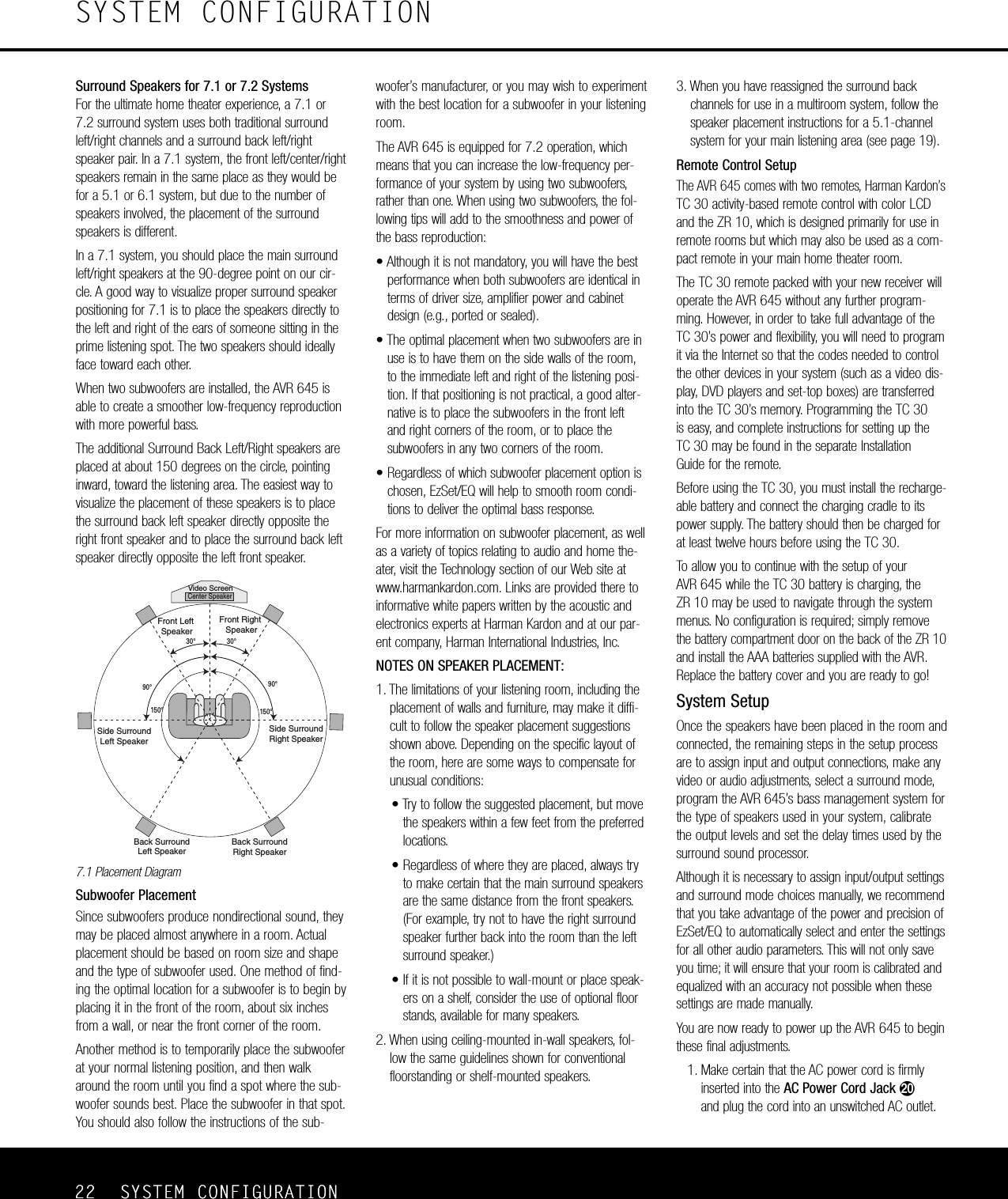
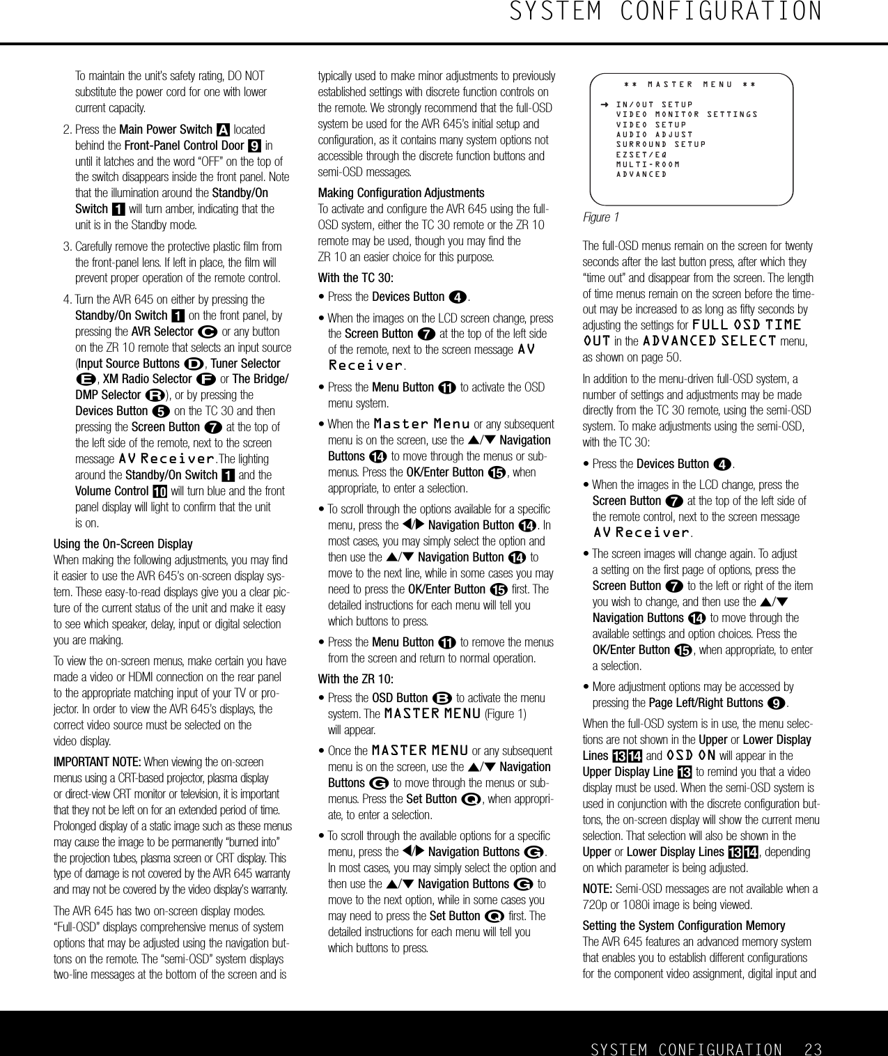
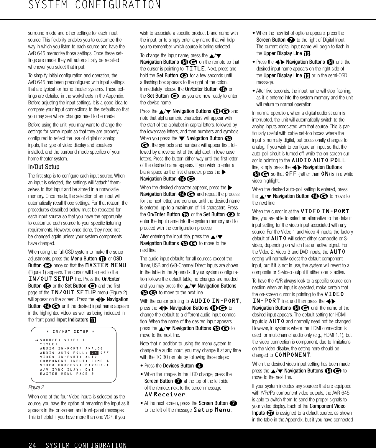
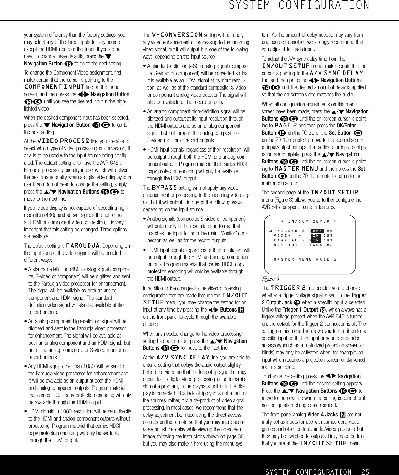
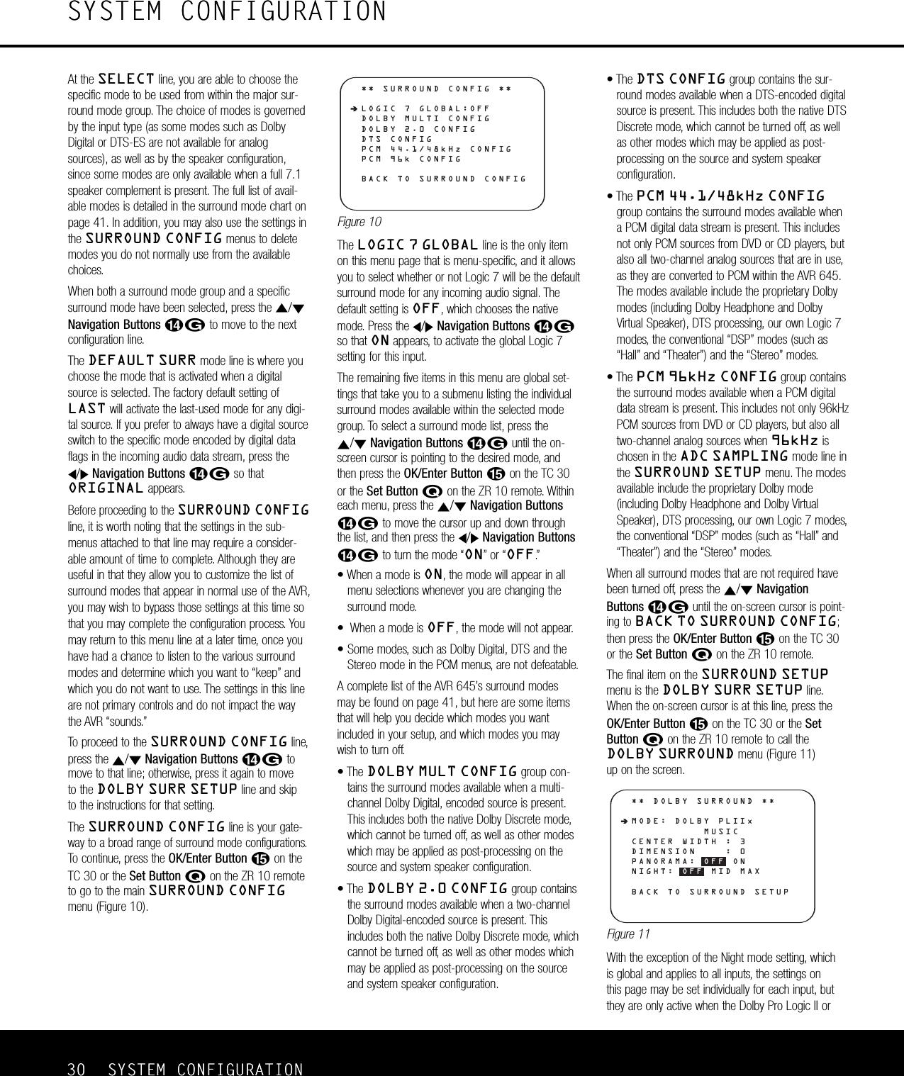
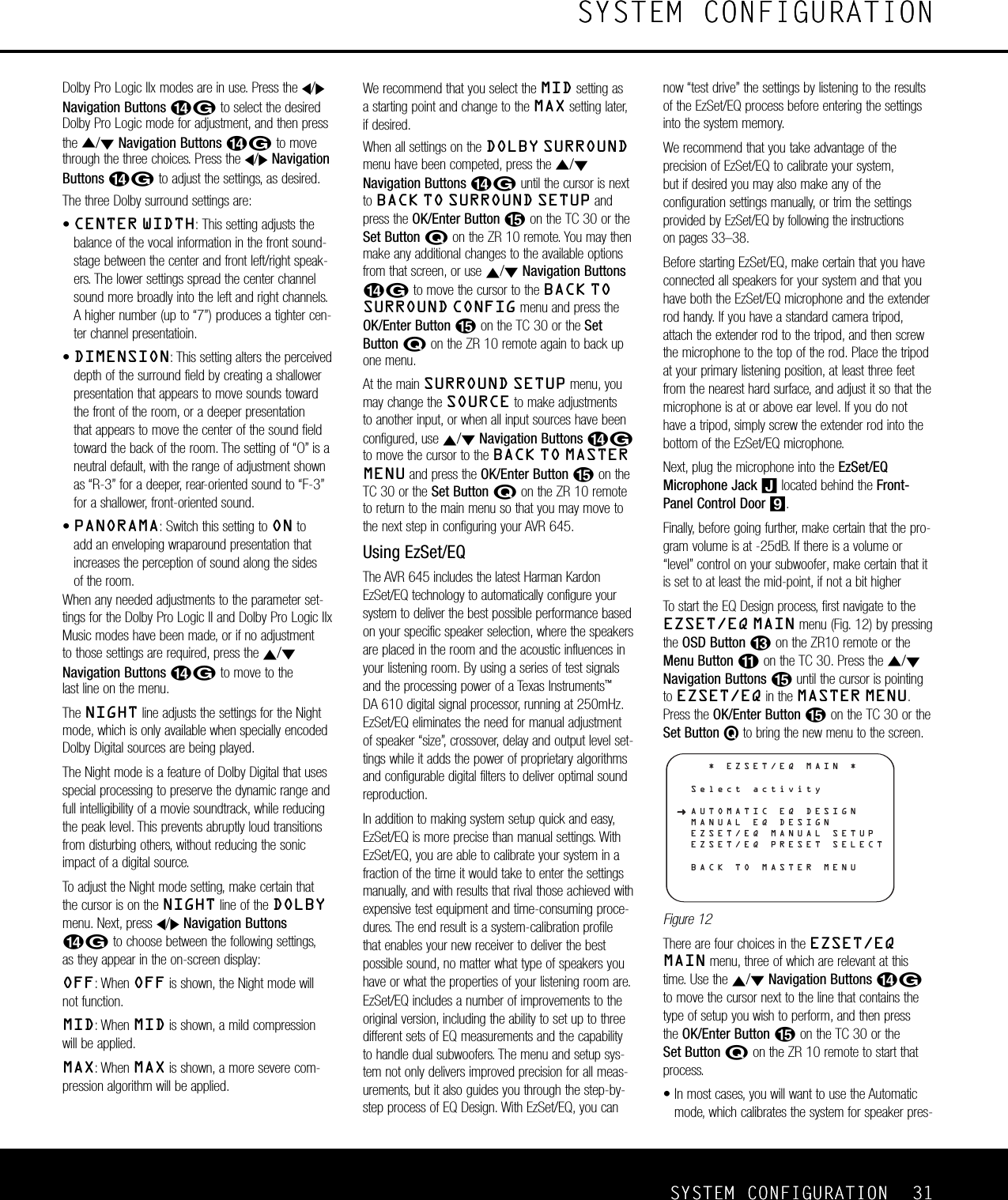
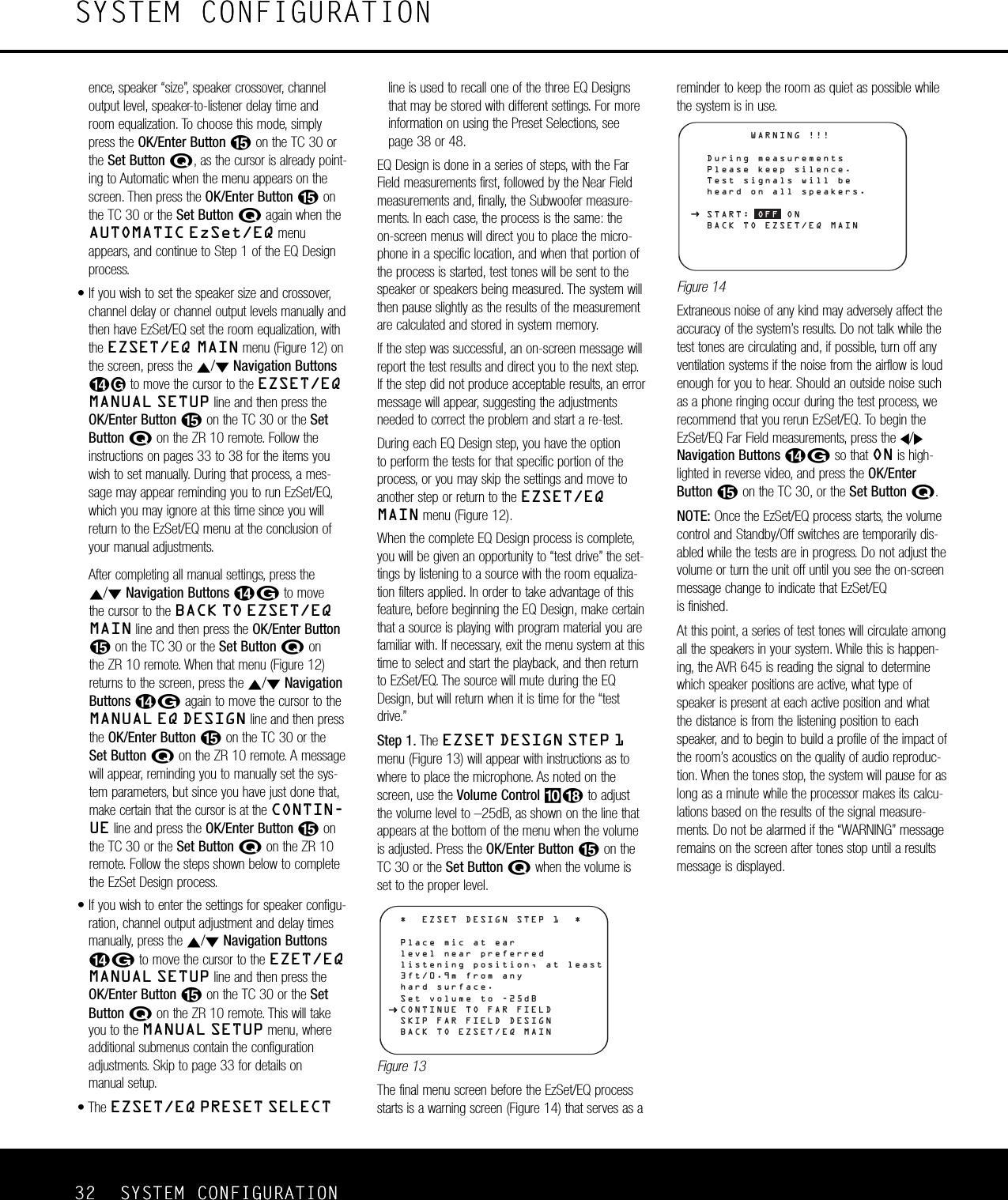
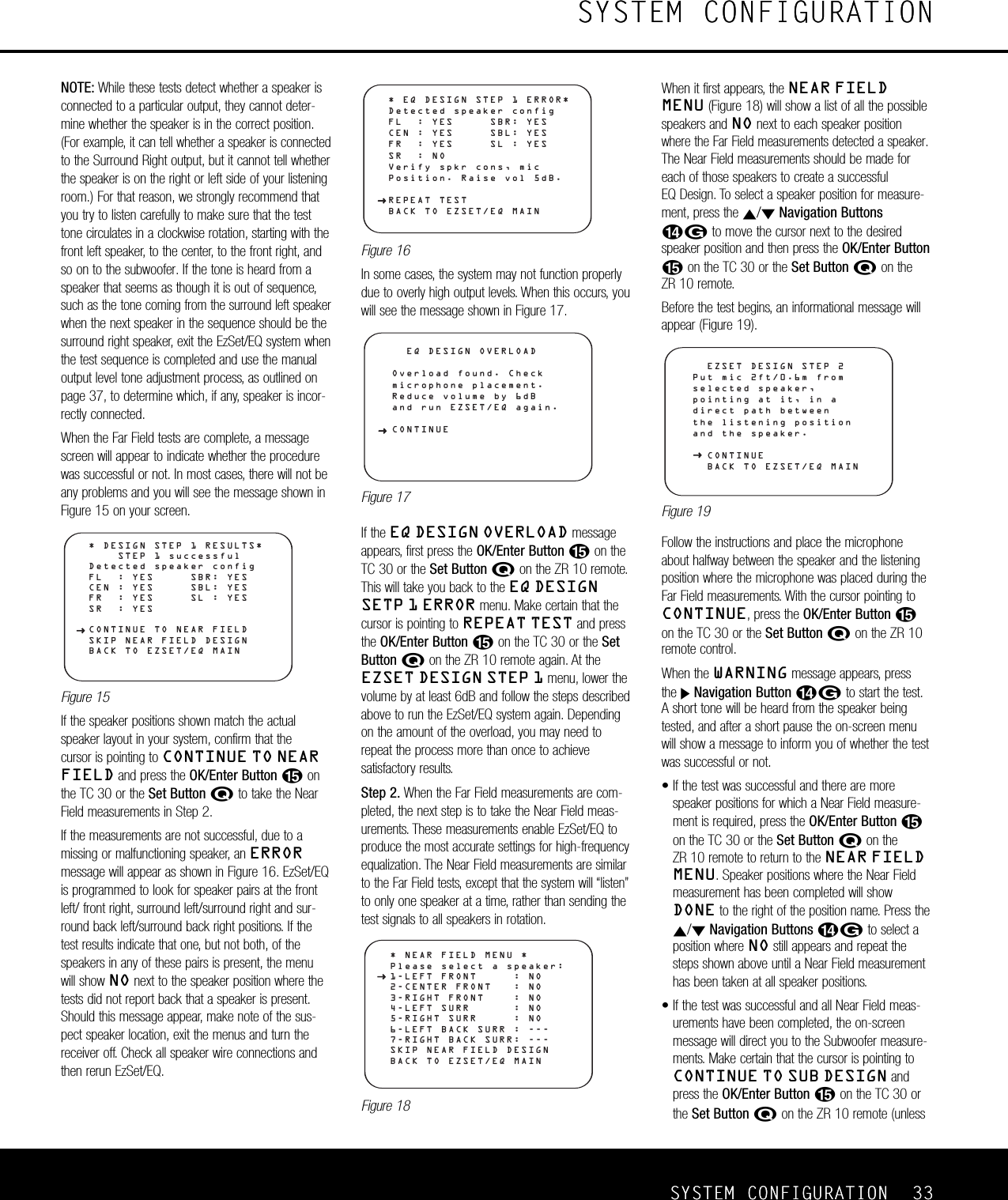
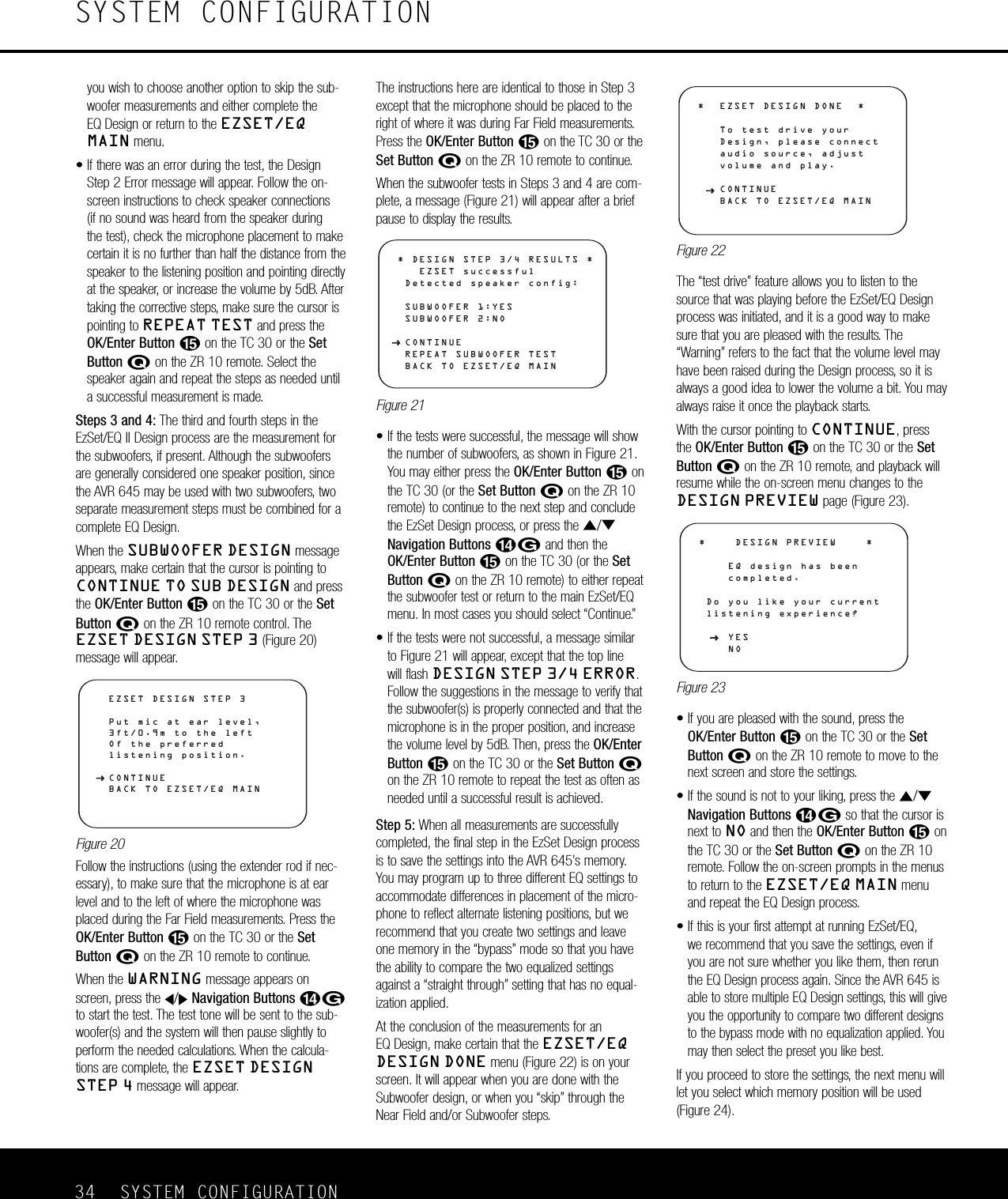
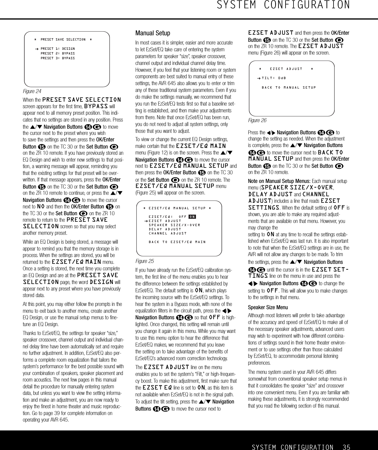
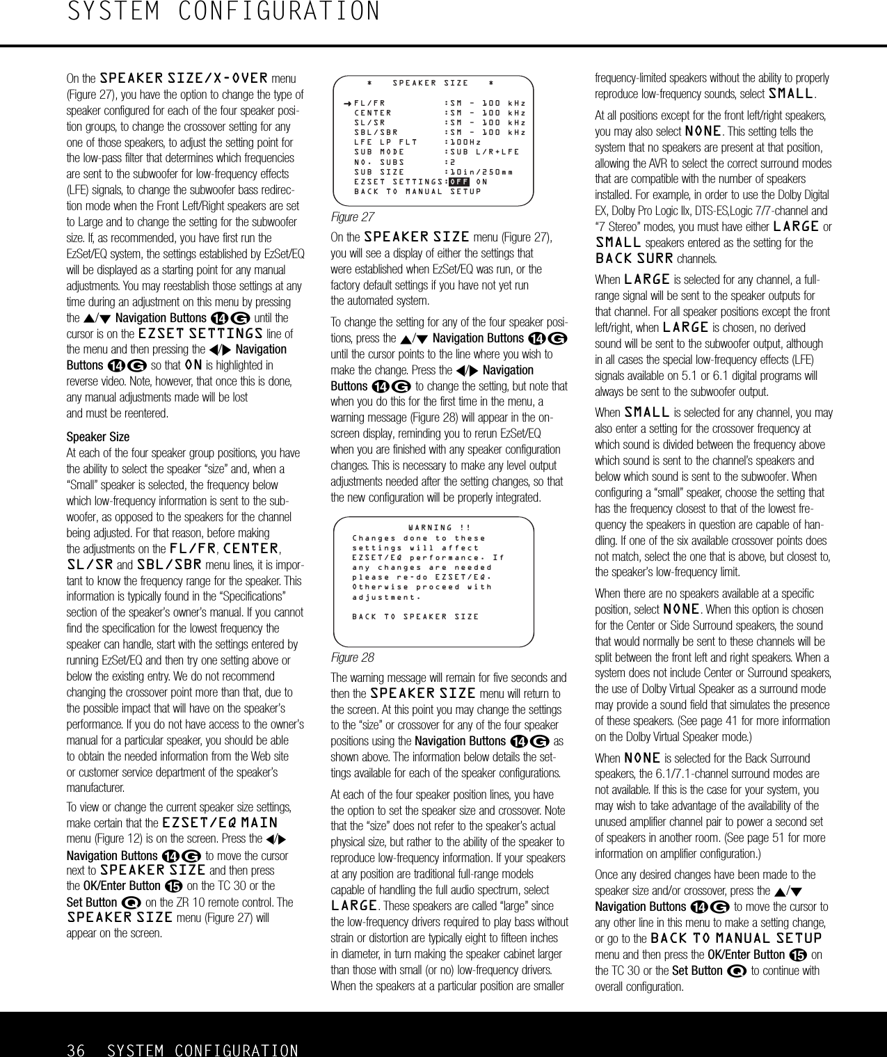
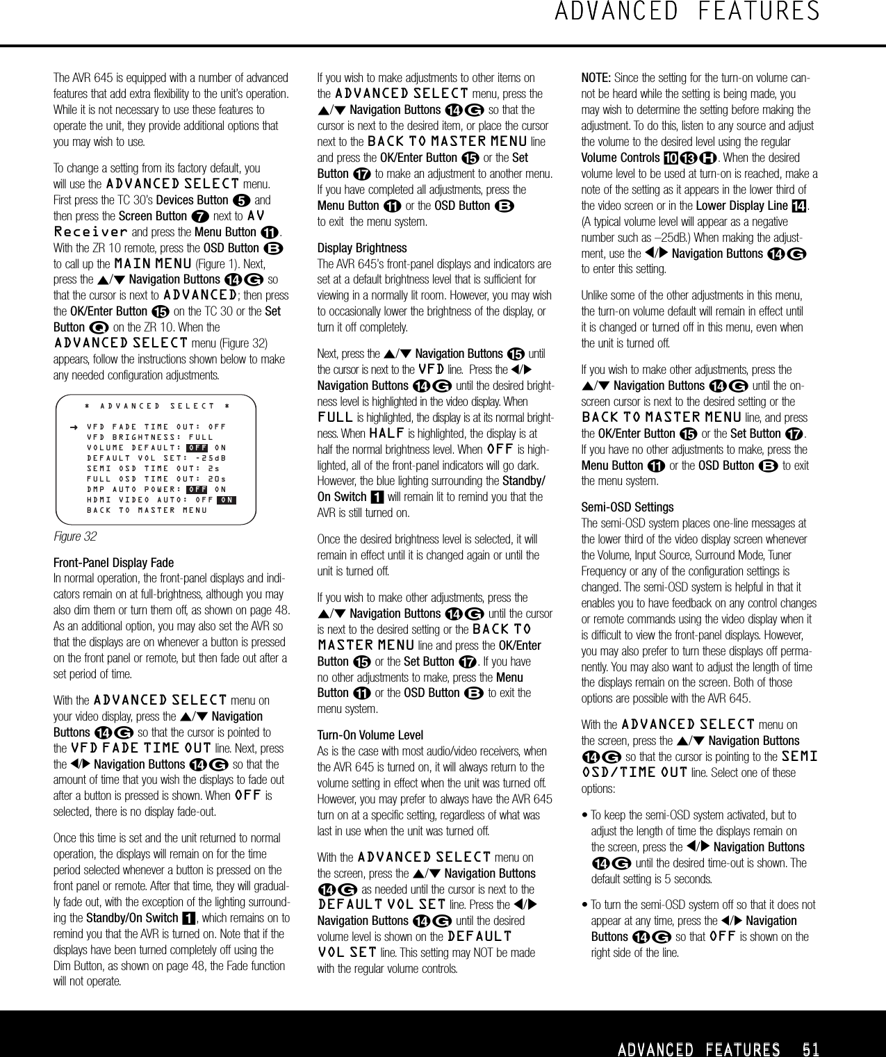
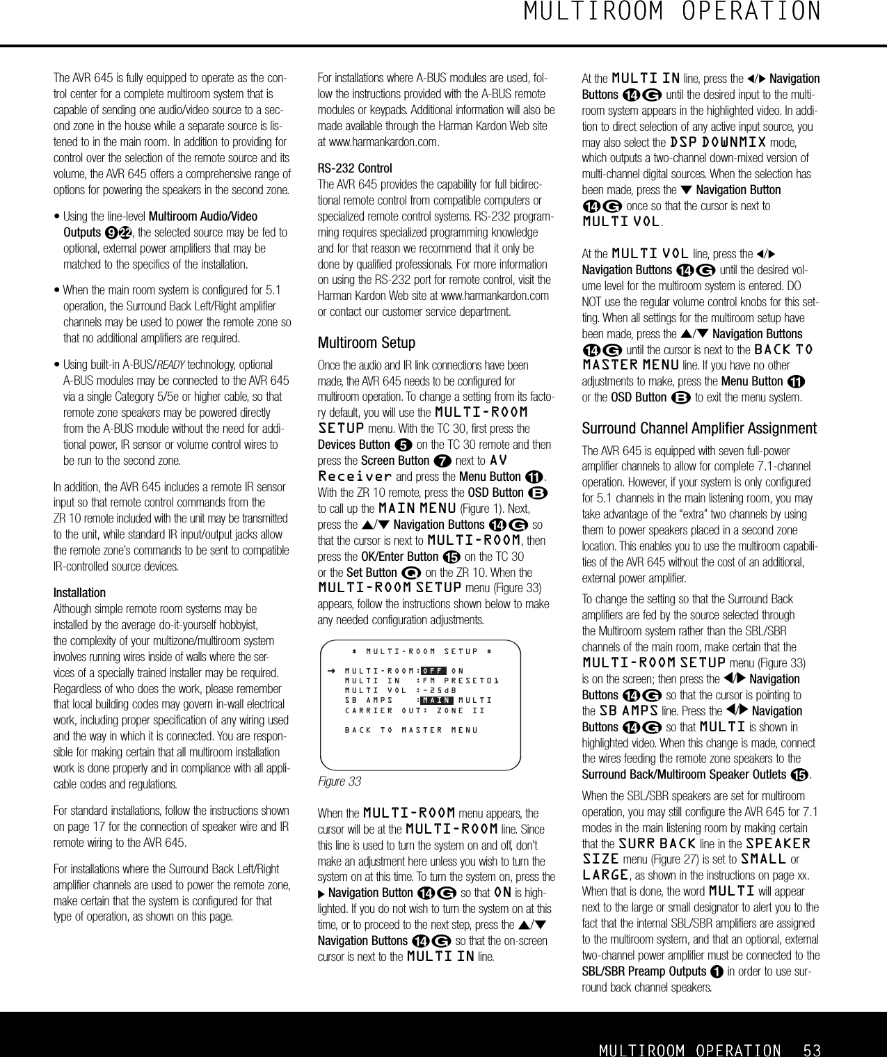
User Manual
Discussion / Help
Navigation