Woori Technology DPR1005 AV RECEIVER User Manual AVR 630 OM
Woori Technology Inc AV RECEIVER AVR 630 OM
UserManual.wiki
>
Woori Technology
>
DPR1005 User Manual
USERS MANUAL
Navigation menu
Upload a User Manual
Namespaces
Wiki Guide
HTML
PDF
Info
Views
User Manual
Discussion / Help
Navigation
![CONFIGURING THE REMOTE 45CONFIGURING THE REMOTEyou must first press the Input Selectors dfor that button, and then press the Command orFunction key. Since we want to program a series of events that occur each time the Power On button is pressed, press the DPR button. In yourspecific macro, this is the first command button.Figure 447. The next display (Figure 45) and the subsequentscreens are where the actual macro programmingtakes place. The words at the left side of the topline of the display show the button that is beingprogrammed (e.g., the Power On Button1orone of the Macro Buttons R) and the indica-tion at the right side of the top line shows thenumber of macro steps available of 20 possiblesteps. Following the instructions on the remote’sLCD screen, press the first key you wish to betransmitted in the macro. In our example, we firstwant the DPR 2005 to turn on, so the PowerButton1should be pressed.Figure 458. Once the first command button for the macro hasbeen pressed, continue to press the buttons youwish to be part of the macro, in the order they willbe used. Press each button within five seconds ofthe last button, remembering to press the InputSelector3when you are changing devicefunctions. As the buttons on the remote arepressed,the remote’s display screen will show thesteps in the macro as they are programmed(Figure 46).Figure 469. For our example, we first want the DPR Power On button pressed, followed by the TV Power On,followed by the Cable Box On, followed by theselection of the Logic 7 mode. To do that, pressthe buttons in this order:• Power On1• VID 2/TV3• Power On1• VID 3/Cable3• Power On1• DPR4• Logic 7hAs each button is pressed to enter it into themacro, you will see the button names appear andthen scroll up on the LCD display as your confir-mation of the key entry (Figure 46).10. When all commands for the macro have beenentered, press the Set Buttonqto save themacro. The display screen will show the button to which the macro has been programmed andthe number of steps used, and the word SAVEDwill blink four times in the lower line of the LCD display. When the display returns to normal, themacro has been entered and the remote is readyfor operation.11. If a macro has been programmed into the PowerOn Button1,it will play back anytime thePower On button is pressed. As the macro plays,you will see the steps appear in the remote’s LCDdisplay. Macros programmed into one of the fourdiscrete Macro buttons may be activated at anytime by pressing the appropriate button.Erasing a MacroOnce a macro has been created and stored in theDPR remote’s memory, you have the option of erasingit. You may do this at any time by following thesesteps:1. Press and hold the Program ButtonOforabout three seconds while the message shown in Figure 18 appears in the remote’s LCDInformation Display2.Release the buttonwhen the red light under the Set Buttonqappears.2. The remote’s MAIN MENU message (Figure19), will appear in the LCD display and the SetButtonqwill remain illuminated in red. Pressthe ⁄Navigation Buttonothree times sothat MACRO appears on the bottom line of theLCD screen, as shown in Figure 40. Press theSet Buttonqto enter the main macro menubranch.3. At the next menu screen (Figure 47), press the⁄/¤Navigation Button ountil the bottomline in the remote’s LCD display reads ERASE AMACRO.Press the Set Buttonqto begin theprocess of erasing a macro.Figure 474. The next display screen (Figure 48) is where youselect which macro will be erased. Press the⁄/¤Navigation Button ountil the numberof the macro you wish to erase appears. For this example we will erase the Power On macrocreated in the previous section. When the nameof the macro to be erased appears, press the Set Buttonq.Figure 485. The word ERASED will flash four times in thebottom line of the remote’s LCD display, and thenthe display will return to its normal condition.When that happens, the macro is erased and theremote is returned to normal operation.Read a MacroTo check the commands stored in the remote’s memoryfor one of the buttons, follow these steps:1. Press and hold the Program ButtonOforabout three seconds while the message shown in Figure 18 appears in the remote’s LCDInformation Display2.Release the buttonwhen the red light under the Set Buttonqappears.2. The remote’s MAIN MENU message (Figure18), will appear in the LCD display and the SetButtonqwill remain illuminated in red. Pressthe ⁄Navigation Buttonothree times sothat MACRO appears on the bottom line of theLCD screen, as shown in Figure 40. Press theSet Buttonqto enter the main macro menubranch.3. At the next menu screen (Figure 49), press the⁄/¤Navigation Button ountil the bottomline in the remote’s LCD display shows READ AMACRO.Press the Set Button qto begin theprocess of reading a macro.Figure 494. The next display screen (Figure 50) is where youselect the macro to be read. Press the ⁄/¤Navigation Button ountil the name of themacro you wish to read appears. For this example,we will read back the Power On macro created ina previous section. When the name of the macroto be read appears, press the Set Buttonq.Figure 505. As soon as the Set button is pressed, the first twosteps in the macro will be appear in the remote’sLCD screen. You may then use the ⁄/¤Navigation Button oto step up or downthrough the list of commands stored as themacro. As you read the display, you will see InputSelector Buttons3appear in brackets, (e.g.,[DPR]). When the step in the macro is a func-tion, navigation or any other button, it will appearREAD A MACROPOWER ONMACROREAD A MACROERASE A MACROPOWER ONMACROERASE A MACRO[AVR][AVR] POWER ONPOWER ON 00/20SELECT KEY PRESSSELECT A DEVICEAVRDPR 2005 OM 3/8/04 1:45 PM Page 45](https://usermanual.wiki/Woori-Technology/DPR1005/User-Guide-424628-Page-45.png)
![next to the bracketed read-out of the underlyingdevice (e.g., [AVR] POWER ON).6. When you are finished reviewing the macro’s contents, press the Set Buttonqto return the remote to normal operation.Punch-Through ConfigurationPunch-through is a capability of the remote that allows the Volume controls, Channel Up/Down buttonsor Transport keys (Play, Stop, Record, Fast Forwardand Reverse, and Skip Up/Down) to link to a differentdevice. For example, if your TV, cable box or satellitereceiver is connected through the DPR 2005, you will most likely want to use the DPR 2005’s volume con-trol commands even when the remote has been set to issue all other commands for the video device.“Punch-through” enables you to easily program theremote to do this.Volume Punch-ThroughFollow these steps to enable the Volume Up/Downand Mute controls from one device to be used whenthe remote is otherwise programmed for a differentdevice.NOTE FOR VOLUME PUNCH-THROUGH: Theremote’s default settings are for the DPR 2005’s vol-ume controls, to be used when any input or device isselected, with the exception of the VID 2/TV button.There is no need to program the remote for volumepunch-through for the DPR 2005’s controls with othersources, such as DVD. To have the DPR 2005’s vol-ume commands used when the TV device is selected,follow these steps:1. Press and hold the Program ButtonOforabout three seconds while the message shown in Figure 18 appears in the remote’s LCDInformation Display2.Release the buttonwhen the red light under the Set Buttonqappears.2. The remote’s MAIN MENU message (Figure19), will appear in the LCD display and the SetButtonqwill remain illuminated in red. Pressthe ⁄/¤Navigation Button ountilPUNCH-THROUGH appears on the bottomline of the LCD screen, as shown in Figure 51.Press the Set Buttonqto enter the mainpunch-through menu branch.Figure 513. At the next menu screen (Figure 52) press the Set Buttonqto begin programming theremote for Volume punch-through.Figure 524. The next display screen (Figure 53) is where you select the device that will receive the punch-through commands. In our example, that is the VID 2/TV button, as that is where we want theDPR 2005’s volume controls to be active. Pressthe ⁄/¤Navigation Button ountil thename of the base device appears and then pressthe Set Buttonq.Figure 535. At the next display screen (Figure 54), you willselect the device whose Volume Up/Down andMute commands will be used. Press the ⁄/¤Navigation Button ountil the desired device’sname appears to the right of the device in use. Inour example, that is the DPR 2005 (indicated byDPR). When the desired combination of devicesappears, press the Set Buttonq.Figure 546. When the Set button is pressed, the display willchange to show you that the new combination ofcontrol commands is being saved to the unit’smemory, as shown in Figure 55. The wordSAVED will flash four times and then the remotewill return to normal operation.Figure 557. Once the punch-through is programmed, the Volume Up/Down and Mute buttons of the seconddevice named will be used when those buttonsHWare pressed while the master device is in use.Returning the Volume Control Settings to Default OperationIf you wish to remove the Volume punch-through sothat the commands for Volume and Mute are returnedto the factory default setting, follow the steps shownabove, except that in Steps 4 and 5, select the samedevice for both the DEVICE IN USE on the leftside of the bottom line and the PUNCH-THROUGHdevice. In the example used, the display to return theremote to default settings will appear as shown inFigure 56.Figure 56Channel Punch-ThroughChannel punch-through allows the Channel Up/Downbuttons to send commands to a different device thanthe one that has been selected for other commands.For example, you may wish to use a cable box orsatellite receiver as the source for a VCR, so youwould want the Channel Up/Down Buttons Ytotransmit commands to the cable box even though theother button commands are programmed to operatethe VCR.To program the remote for channel punch-through,follow these steps. This example will show how to pro-gram channel punch-through so that the commandsprogrammed for Channel Up/Down for the VID 3/Cable device will be transmitted when the VID 1/VCRdevice has been selected as the current device.1. Press and hold the Program ButtonOforabout three seconds while the message shown in Figure 18 appears in the remote’s LCDInformation Display2.Release the buttonwhen the red light under the Set Buttonqappears.2. The remote’s MAIN MENU message (Figure19), will appear in the LCD display and the Set Buttonqwill remain illuminated in red.Press the ⁄/¤Navigation Button ountilPUNCH-THROUGH appears on the bottomline of the LCD screen, as shown in Figure 51.Press the Set Buttonqto enter the mainpunch-through menu branch.3. At the next menu screen, press the ⁄/¤Navigation Button ountil CHANNELappears on the bottom line of the LCD screen,as shown in Figure 57. Press the Set Buttonqto begin programming the remote for channel punch-through.Figure 574. The next display screen (Figure 58) is where youselect the device that will receive the punch-through commands. In our example, that is the VID 1/VCR button, as that is where we want thecable box’s channel controls to be active. Pressthe ⁄/¤Navigation Button ountil thename of the base device appears and then press the Set Buttonq.Figure 585. At the next display screen (Figure 59), you willselect the device whose Channel Up/Down com-mands will be used. Press the ⁄/¤NavigationDEVICE IN USEVCRPUNCH-THROUGHCHANNELPUNCH-THROUGHTV<-TVTV<-DPR [VOL] SAVEDPUNCH-THROUGHTV<-AVRDEVICE IN USETVPUNCH-THROUGHVOLUMEMAIN MENUPUNCH-THROUGH46 CONFIGURING THE REMOTECONFIGURING THE REMOTEDPR 2005 OM 3/8/04 1:45 PM Page 46](https://usermanual.wiki/Woori-Technology/DPR1005/User-Guide-424628-Page-46.png)
![CONFIGURING THE REMOTE 47CONFIGURING THE REMOTEButton ountil the desired device nameappears to the right of the device in use. In ourexample, that is the cable box. When the desiredcombination of devices appears, press the SetButtonq.Figure 596. When the Set button is pressed, the display willchange to show you that the new combination of control commands is being saved to the unit’smemory, as shown in Figure 60. The wordSAVED will flash four times and then the remotewill return to normal operation.Figure 607. Once the punch-through is programmed, theChannel Up/Down Buttons of the seconddevice named will be used when those buttonsYare pressed while the master device is in use.Returning the Channel Control Settings to Default OperationIf you wish to remove the Channel Punch-Through so that the commands for Channel Up/Down arereturned to the factory default setting, follow the stepsshown above, except that in Steps 4 and 5, select the same device for both the DEVICE IN USE onthe left side of the bottom line and the PUNCH-THROUGH device. In the example used, the displayto return the remote to default settings will appear asshown in Figure 61.Figure 61Transport Punch-ThroughThe Play Z,Stop J,Fast Forward/ReverseI,Pause J,RecordJand Skip Up/DownKTransport Controls are set at the factory to oper-ate your DVD player, or the controls of a specificdevice such as a VCR or CD player when they areselected. However, by using the Transport Punch-Through feature you may program these controls totransmit the commands for a different device. Forexample, you may wish to operate the transport of aVCR connected to the VID 1/VCR input as the default,rather than the button for a DVD player, as shown inthe following example.1. Press and hold the Program ButtonOforabout three seconds while the message shown in Figure 18 appears in the remote’s LCDInformation Display2.Release the buttonwhen the red light under the Set Buttonqappears.2. The remote’s MAIN MENU message (Figure17), will appear in the LCD display and the SetButtonqwill remain illuminated in red. Pressthe ⁄/¤Navigation Button ountilPUNCH-THROUGH appears on the bottomline of the LCD screen, as shown in Figure 51.Press the Set Buttonqto enter the mainpunch-through menu branch.3. At the next menu screen, press the ⁄/¤Navigation Button ountil TRANSPORTappears on the bottom line of the LCD screen, asshown in Figure 62. Press the Set Buttonqto begin programming the remote for transportpunch-through.Figure 624. The next display screen (Figure 63) is where youselect the device that will receive the punch-through commands. In our example, that is the TV button, as that is where we want the VCR’stransport controls to be active. Press the ⁄/¤Navigation Button ountil the name of thebase device appears and then press the SetButtonq.Figure 635. At the next display screen (Figure 64), you willselect the device whose transport commands willbe used. Press the ⁄/¤Navigation Buttonountil the desired device name appears to theright of the device in use. In our example, that isthe VCR. When the desired combination ofdevices appears, press the Set Buttonq.Figure 646. When the Set button is pressed, the display willchange to show you that the new combination ofcontrol commands is being saved to the unit’smemory, as shown in Figure 65. The wordSAVED will flash four times and then the remotewill return to normal operation.Figure 657. Once the punch-through is programmed, the transport buttons of the second device named will be used when those buttons are pressedwhile the master device is in use.Returning the Transport Control Settings toDefault OperationIf you wish to remove the Transport Punch-Through sothat the transport commands are returned to the fac-tory default setting, follow the steps shown above,except that in Steps 4 and 5, select the same devicefor both the DEVICE IN USE on the left side of thebottom line and the PUNCH-THROUGH device. Inthe example used, the display to return the remote todefault settings will appear as shown in Figure 66.Figure 66EzSet ConfigurationHarman Kardon’s patented EzSet feature makes it easierthan ever to calibrate the output levels on your newreceiver for maximum playback accuracy. In additionto automatically setting the levels, the DPR remote’sLCD display allows the unit to be used as a directread-out SPL meter. Complete instructions for usingthe EzSet features of the DPR remote are found onpages 27 – 29 of this owner’s manual.In most cases you will find it easier to access theEzSet capabilities directly by pressing the SPL SelectButton iand following the menu prompts asdetailed on pages 27 and 28. However, there is onefunction of the remote that is only available throughthe remote’s menu system being described in thissection.To avoid having the calibration settings created withEzSet changed accidentally, the remote allows you todisable the SPL Select Button ion the remote.To de-activate the button, follow these steps:1. Press and hold the Program ButtonOforabout three seconds while the message shown in Figure 18 appears in the remote’s LCDInformation Display2.Release the buttonwhen the red light under the Set Buttonqappears.2.The remote’s MAIN MENU message (Figure 19),will appear in the LCD display and the Set Buttonqwill remain illuminated in red. Press the⁄/¤Navigation Button ountil SET SPKRLEVELS appears on the bottom line of the LCDscreen, as shown in Figure 67. Press the SetButtonqto enter the main EzSet menubranch.Figure 67MAIN MENUSET SPKR LEVELSPUNCH-THROUGHTV<-TVTV<-VCR [TRS] SAVEDPUNCH-THROUGHTV<-VCRDEVICE IN USETVPUNCH-THROUGHTRANSPORTPUNCH-THROUGHVCR<-VCRVCR<-CBL [CHAN] SAVEDPUNCH-THROUGHVCR<-CBLDPR 2005 OM 3/8/04 1:45 PM Page 47](https://usermanual.wiki/Woori-Technology/DPR1005/User-Guide-424628-Page-47.png)
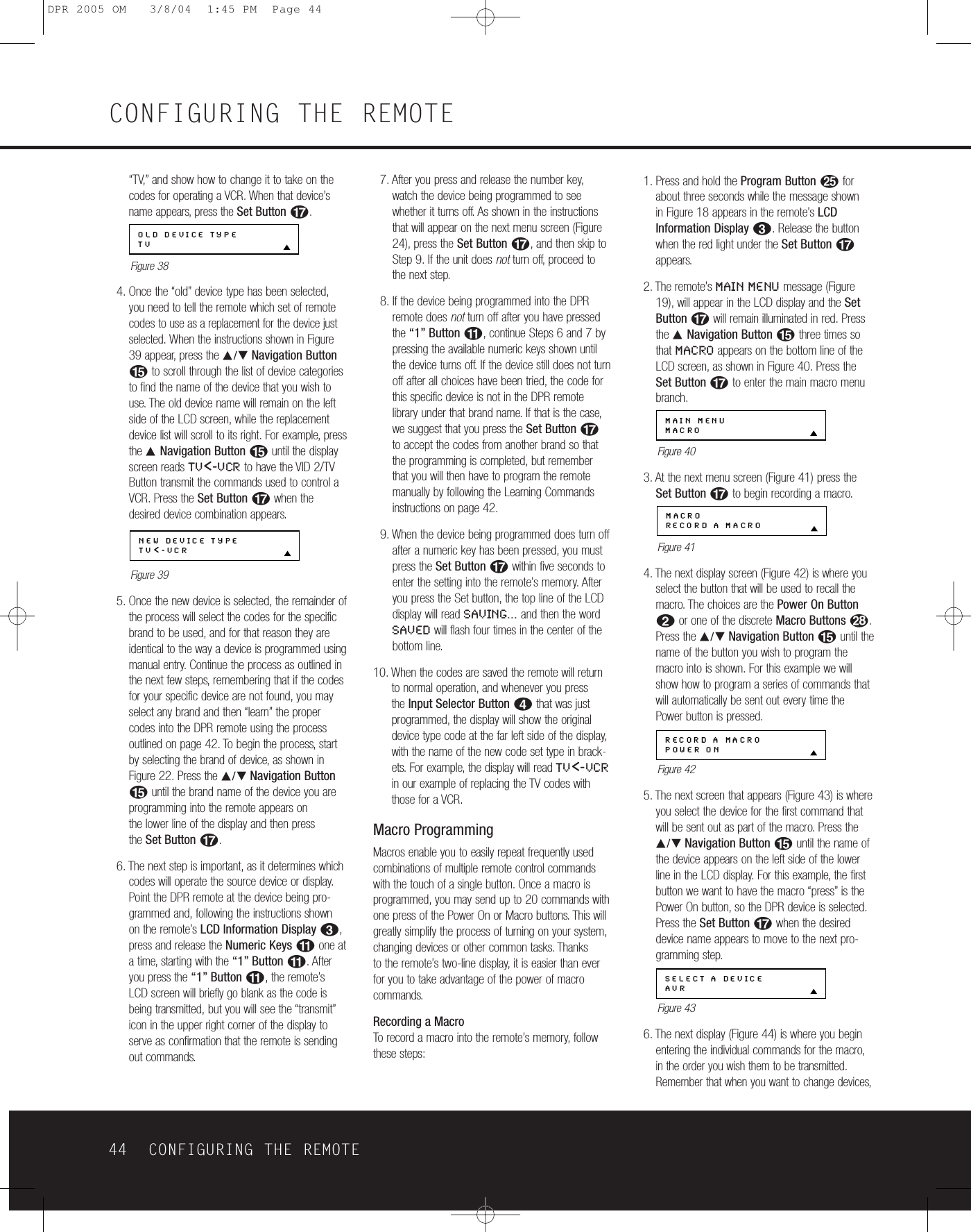
![3. At the next menu screen (Figure 68) press the⁄/¤Navigation Buttons oonce so thatEZSET DISABLE appears in the lower line ofthe LCD display.Figure 684. Within five seconds, press the Set Buttonqtodisable the SPL Select Button i.Once theSet Buttonqis pressed the word EXITINGwill flash four times in the lower line of the LCDdisplay and then it will return to normal operation.Once these steps are completed, when the SPLSelect Button iis pressed the remote will show EZSET DISABLE and it will not be activated.To restore the EzSet feature to normal operation,repeat the procedure outlined above, except that inStep 3 you should press the ⁄/¤NavigationButton oso that EZSET ENABLE appears in thelower line of the LCD display. When that displayappears, press the Set Buttonqand the EzSetfeature will be reactivated. You may then press theClear Button9to exit the remote’s menu systemand return to normal operation or press the SetButtonqagain to immediately use the EzSet feature to calibrate the system as shown on pages 27 and 28.RenamingWhile the names given to the buttons and inputs onthe remote represent recognizable categories ofaudio/video products, system operation may be easierif the displays shown in the remote’s LCD screen arecustomized to reflect the specific characteristics of aplayback source’s brand name or the new functiongiven to a specific button when one remote’s controlsare programmed into the DPR remote. The DPRremote allows you to change the name of either amaster device or any button on the remote using thefollowing steps.Renaming a DeviceTo rename a specific device/input source button, fol-low these steps. For this example, we will show youhow to rename the Device/Input Selector normallyshown as “TV” to “HDTV TUNER.”1. Press and hold the Program ButtonOforabout three seconds while the message shown in Figure 16 appears in the remote’s LCDInformation Display2.Release the buttonwhen the red light under the Set Buttonqappears.2.The remote’s MAIN MENU message (Figure 17),will appear in the LCD display and the Set Buttonqwill remain illuminated in red. Press the ⁄/¤Navigation Button ountil RENAME appearson the bottom line of the LCD screen, as shown inFigure 69.Figure 693. At the next menu screen press the ⁄/¤Navigation Button ountil RENAMEDEVICE appears on the bottom line of the LCD screen, as shown in Figure 70. Press the Set Buttonqto begin renaming a device.Figure 704. The next display screen (Figure 71) is where youselect the device that will be renamed. In ourexample, that is the TV button. Press the ⁄/¤Navigation Button ountil the name of thebase device appears and then press the SetButtonq.Figure 715. At the next menu screen you will see the devicename on the bottom line of the display with ablinking cursor box to the right of the devicename. Press the ‹Navigation Button otoreturn the blinking cursor to the far left side of thedisplay line. You may then retitle the device nameas shown in the next step.6. To enter the new name, press the Numeric KeysA.The letters above the numbered buttonsindicate which letter or symbol will appear whenthe button is pressed during the renamingprocess. The first press of the button will enter thefirst letter shown, subsequent presses of the samebutton will change the display to the other lettersabove that numbered key. For example, since thefirst letter we need to rename the input to HDTVTuner is an “H”, you would locate the “H” abovethe “4” button, and press the button twice. Thefirst press shows a “G,” the second press changesit to an “H.” Consult the table at the end of thissection to see which characters pressing a partic-ular button generates.7. After you enter the first letter of the new devicename, there are three options for entering the nextcharacter:a. To enter a letter that requires a different numeric key to be pressed, simply press thatbutton. The cursor will automatically move to the next position and the first letter accessed by the new button will appear. Following ourexample, the next letter needed is a “D,” so you would press the “3” button once.b. To enter a letter that uses the same numerickey, you must first press the ›NavigationButtonoto move the blinking cursor blockto the next position. Then press the NumericKeyAas required to enter the desired letter.c.To enter a blank space, press the ›NavigationButtonotwice. The first press will move thecursor to the right, and the second press willmove the cursor one more space to the right,leaving a blank space between the last letterand the next one.8. Repeat Step 7 as needed to enter all the neededletters, numbers, characters and spaces.9. When the text entry is complete, press the Set Buttonq.The LCD display will blinkDEVICE RENAMED three times and thenreturn to normal operation.Once a device is renamed you will see the new nameon the top line of the remote’s LCD display wheneverthe Input//Device Selector3is pressed, or whenany other command/function button on the remote ispressed after the main Device Selector is pressed.Note that renaming a device in the remote will notchange the name of the input used by the on-screenmenu system of the DPR 2005.NOTES ON RENAMING DEVICES:• To move the cursor to the right or left of the displayduring the renaming process, press the ‹/›Navigation Buttonsoas required.• The table below shows the letters, numbers andcharacters that may be accessed by pressing theNumeric Keys:Key Characters Key Characters1[,],/,1 6 M,N,O,62 A,B,C,2 7 P,Q,R,S,73D,E,F,3 8 T,U,V,84G,H,I,4 9 W,X,Y,Z,95J,K,L,5 0 -,.,#,0• Renaming a device changes the name of the deviceonly, not any of the individual key functions withinthat device memory. To change the name of an individual device, follow the instructions in the nextsection.RENAME DEVICETVRENAMERENAME DEVICEMAIN MENURENAMESET SPKR LEVELSEZSET DISABLE48 CONFIGURING THE REMOTECONFIGURING THE REMOTEDPR 2005 OM 3/8/04 1:45 PM Page 48](https://usermanual.wiki/Woori-Technology/DPR1005/User-Guide-424628-Page-48.png)