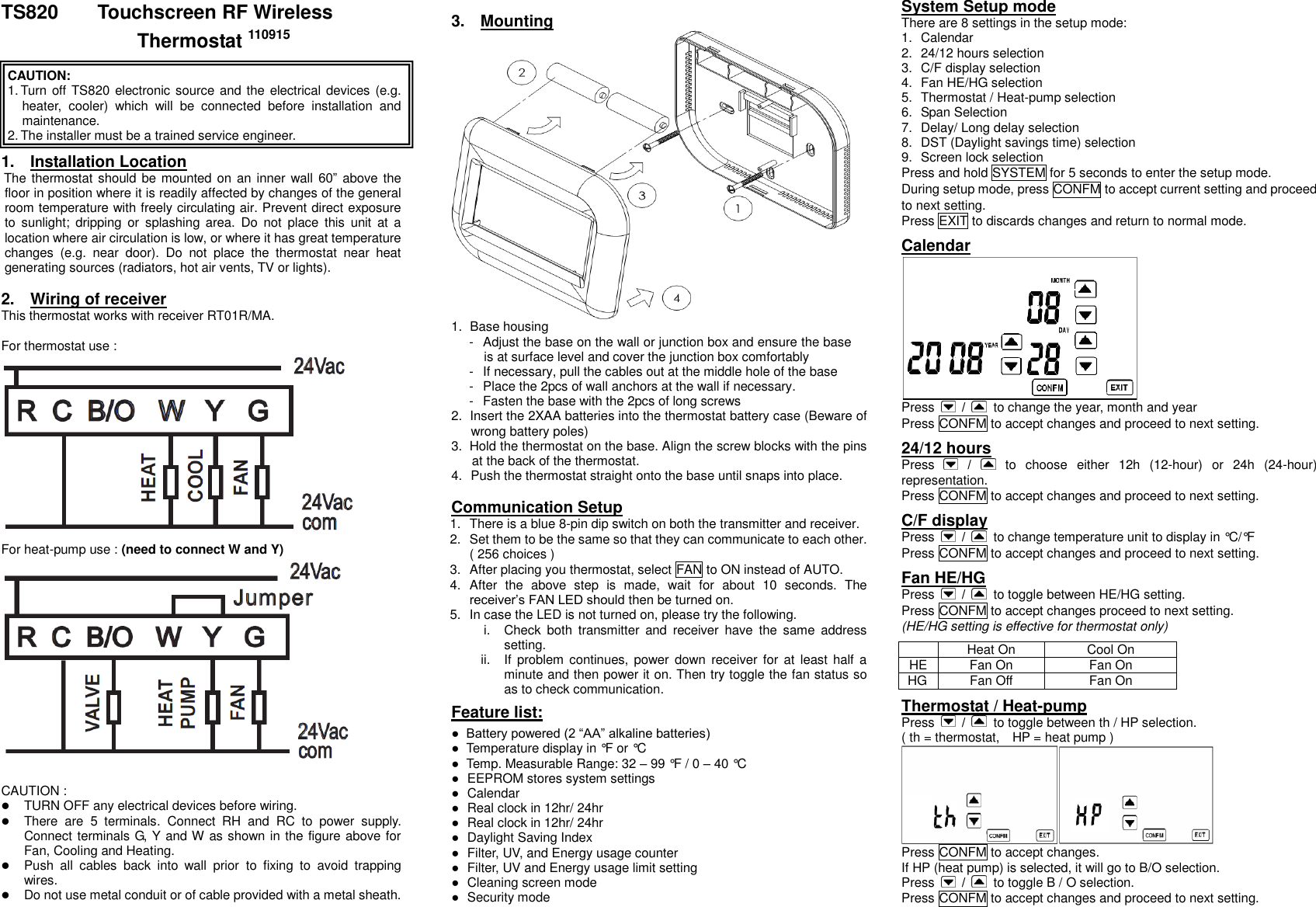
World Excel 20198201820010 Touchscreen Thermostat User Manual TS01 Touchscreen Programmable Thermostat 080115

World Excel Company Ltd Touchscreen Thermostat TS01 Touchscreen Programmable Thermostat 080115

users manual

TS820      Touchscreen RF Wireless Thermostat 110915   CAUTION:   1. Turn off TS820 electronic source and the electrical devices (e.g. heater,  cooler)  which  will  be  connected  before  installation  and maintenance.   2. The installer must be a trained service engineer.  1.  Installation Location The thermostat should be mounted on an inner wall 60”  above the floor in position where it is readily affected by changes of the general room temperature with freely circulating air. Prevent direct exposure to  sunlight;  dripping  or  splashing  area.  Do  not  place  this  unit  at  a location where air circulation is low, or where it has great temperature changes  (e.g.  near  door).  Do  not  place  the  thermostat  near  heat generating sources (radiators, hot air vents, TV or lights).  2.  Wiring of receiver This thermostat works with receiver RT01R/MA.  For thermostat use :  For heat-pump use : (need to connect W and Y)   CAUTION :    TURN OFF any electrical devices before wiring.  There  are  5  terminals.  Connect  RH  and  RC  to  power  supply. Connect terminals G, Y and W as shown in the figure above for Fan, Cooling and Heating.    Push  all  cables  back  into  wall  prior  to  fixing  to  avoid  trapping wires.  Do not use metal conduit or of cable provided with a metal sheath.  3.  Mounting  1.  Base housing -  Adjust the base on the wall or junction box and ensure the base is at surface level and cover the junction box comfortably -  If necessary, pull the cables out at the middle hole of the base -  Place the 2pcs of wall anchors at the wall if necessary. -  Fasten the base with the 2pcs of long screws 2.  Insert the 2XAA batteries into the thermostat battery case (Beware of wrong battery poles) 3.  Hold the thermostat on the base. Align the screw blocks with the pins at the back of the thermostat. 4.  Push the thermostat straight onto the base until snaps into place.  Communication Setup 1.  There is a blue 8-pin dip switch on both the transmitter and receiver. 2.  Set them to be the same so that they can communicate to each other. ( 256 choices ) 3.  After placing you thermostat, select FAN to ON instead of AUTO.   4.  After  the  above  step  is  made,  wait  for  about  10  seconds.  The receiver’s FAN LED should then be turned on. 5.  In case the LED is not turned on, please try the following. i.  Check  both  transmitter  and  receiver  have  the  same  address setting. ii.  If  problem continues,  power down  receiver for at  least half  a minute and then power it on. Then try toggle the fan status so as to check communication.   Feature list: ● Battery powered (2 “AA” alkaline batteries) ●  Temperature display in °F or °C   ●  Temp. Measurable Range: 32 – 99 °F / 0 – 40 °C ●  EEPROM stores system settings ●  Calendar ●  Real clock in 12hr/ 24hr ●  Real clock in 12hr/ 24hr ●  Daylight Saving Index ●  Filter, UV, and Energy usage counter ●  Filter, UV and Energy usage limit setting ●  Cleaning screen mode ●  Security mode System Setup mode There are 8 settings in the setup mode: 1.  Calendar 2.  24/12 hours selection 3.  C/F display selection 4.  Fan HE/HG selection 5.  Thermostat / Heat-pump selection 6.  Span Selection 7.  Delay/ Long delay selection 8.  DST (Daylight savings time) selection 9.  Screen lock selection Press and hold SYSTEM for 5 seconds to enter the setup mode. During setup mode, press CONFM to accept current setting and proceed to next setting. Press EXIT to discards changes and return to normal mode.  Calendar  Press    /    to change the year, month and year Press CONFM to accept changes and proceed to next setting.    24/12 hours Press    /    to  choose  either  12h  (12-hour)  or  24h  (24-hour) representation. Press CONFM to accept changes and proceed to next setting.  C/F display Press    /    to change temperature unit to display in °C/°F Press CONFM to accept changes and proceed to next setting.  Fan HE/HG Press    /    to toggle between HE/HG setting. Press CONFM to accept changes proceed to next setting. (HE/HG setting is effective for thermostat only)   Heat On Cool On HE Fan On Fan On HG Fan Off Fan On  Thermostat / Heat-pump Press    /    to toggle between th / HP selection. ( th = thermostat,    HP = heat pump )  Press CONFM to accept changes. If HP (heat pump) is selected, it will go to B/O selection. Press    /    to toggle B / O selection. Press CONFM to accept changes and proceed to next setting.
  Span Selection “P” represents span and will be displayed in either °C / °F depending on the  previous  temperature unit setting. Press    /    to  change span setting. The selectable values  are  0.5°C(1°F)  / 1.0°C(2°F) / 1.5°C(3°F). Press  CONFM  to  accept changes and proceed to next setting.  Delay/ Long delay   Press    /    to change Delay/ Long delay selection. Delay for Heat on and Cool on is to prevent short cycling of system.   Press CONFM to accept changes and proceed to next setting. (  Delay  setting  is  effective  for  thermostat  only.  When  HP  is  selected, there will always be a 4~5 minutes off-on interval.)   Delay Long delay Heat mode 5~10sec 4~5 min Cool mode 4~5 min 4~5 min  DST (Daylight savings time) Press    or    to turn on or off DST function. If the date is in the DST period, the clock will be automatically activated, Press CONFM to accept changes and proceed to next setting. Remark: The DST bases on the USA time zone.  Security lock   Press    or    to turn on/off the screen lock function. Press  CONFM  to  accept  changes.  When  ON  is  selected,  a  4-digit password is required.  The  screen  shows  a  4-digit  password.  Press    /    on  the  left  to change the password number. P1 represents the 1st digit password (read from left), which is selected.   After setting all 4 digits, press CONFM to activate the security mode and return to normal mode. When security mode is activated, “ ” is shown on the LCD and all keys are disabled expect SYSTEM.  Disable the security mode. 1. Press “SYSTEM” and enter the correct password. 2. If  the  password  is  correct,  security  mode  will  be  deactivated. Otherwise the security mode remains activated. (* security lock cannot maintains once power is lost )  View Calendar 1. Press the Weekday to show current date. 2. Press  the  EXIT  to  return  the  normal  mode  or  it  will  automatically return to normal mode after idling for 20 seconds  Clock setting 1. Press CLOCK to enter the clock setting mode.   2. Press    /    to  change  the  hour.  Press  CONFM  to  save  the setting. 3. Press    /    to  change  the  minute.  Press  CONFM  to  save  the setting and return the normal.  Fan Setting When  FAN  is  set  AUTO,  fan  may  be  turned  on  based  on  HE/HG selection. If ON is selected, fan will always be turned on.  Cleaning screen mode 1. Press CLEAR to enter the cleaning screen mode 2. There is a 20 seconds count down. 3. During counting, all keys are disabled. 4. When the counting is done, press EXIT to return to normal mode or press CLEAR to repeat the count down.  Usage TS820 can record the Filter Usage, UV usage and energy usage. The counters count in hour. Each counter is 4-digital long (0~9999).   Filter usage starts counting when the fan is turned on. UV usages start counting when TS820 is turned on. Energy usage counts when either Heat or Cool is on. When the counts reach the set interval, the corresponding usage icons will be shown. 1.  Press USAGE to enter the usage mode.   2.  Filter  counter,  UV  counter  and  Energy  counter  are  shown alternatively by pressing USAGE 3.  Press CLEAR to clear the counts. 4.  Press EXIT to exit the usage mode.  Adjusting Usage Interval Time 1.  Press and hold the USAGE for 5 seconds during usage mode.   2.  Press    /    to change the internal time (0~9999).   3.  Press CONFM to save the setting 4.  Press EXIT to exit the interval setting. (* set interval time to zero to disable counter)  Changing Setting Temperature   1.  The setting temperature is shown on the screen. 2.  For heat mode, the setting temperature can be set from 5oC ~ 29.5oC. / 41oF ~ 85oC 3.  For  cool  mode,  the setting  temperature  can  be  set  from  18.5oC  ~ 35oC / 65oF ~ 95oF Defrost When the room temperature is below to 5°C / 41°F, HEATER will always be turned ON and COOLER will always be turned OFF irrespective to the current control temperature set.    defrost indicator will be shown.    System setting In normal mode, press SYSTEM to enter System mode. System mode is set in the sequence of:   HEAT COOL OFF HEAT   System Mode HEAT MODE Relay will be turned on when the room temperature is lower than the setting temperature COOL MODE Relay will be turned on when the room temperature is higher than the setting temperature OFF MODE Relay will always be turned off at any temperature. LO will be shown when room temperature is below 0°C / 32°F. HI will be shown when room temperature is above 40°C / 99°F. When the heater or cooler is turned on,    and ON will be shown on the LCD.  Low battery If the voltage batteries drop below 2.7V,    icon will be on.  Electrical Interface Temperature measurement:    0~40°C / 32~99°F Control temperature range:    5~35°C / 41~95°F Temperature resolution:                   0.5°C / 1°F Temperature accuracy:                ±0.5°C / ±1°F   Transmitter input voltage:            2 X AA alkaline battery Receiver (RT01R/MA) Input voltage:  24 Vac 50/60Hz Relay contact Current:      1A Max Operating Temperature:                0 ~ 50°C Storage Temperature:      -10 ~ 60°C  FCC Statement The device complies with Part 15 of the FCC Rules. Operation is subject to the following two conditions: (1) this device may not cause  harmful  interference,  and  (2)  this  device  must  accept  any interference  received,  including  interference  that  may  cause undesired operation.   ⚠ Warning:  Changes  or  modifications  to  this  unit  not expressly approved by the party responsible for compliance could void the user’s authority to operate the equipment. NOTE: This equipment has been tested and found to comply with the limits for a Class B digital device, pursuant to Part 15 of the FCC  Rules.  These  limits  are  designed  to  provide  reasonable protection against harmful interference in a residential installation. This  equipment  generates,  uses  and  can  radiate  radio  frequency energy  and,  if  not  installed  and  used  in  accordance  with  the instructions,  may  cause  harmful  interference  to  radio communications. However, there is no guarantee that interference will not occur in a particular  installation.  If  this  equipment  does  cause  harmful interference  to  radio  or  television  reception,  which  can  be determined  by  turning  the  equipment  off  and  on,  the  user  is encouraged to try to correct the interference by on or more of the following measures:  Reorient of relocate the receiving antenna.  Increase the separation between the equipment and receiver.  Connect the equipment into an outlet  on a circuit different from that to which the receiver is needed.  Consult the dealer or an experienced radio/TV technician for help  Marra Air Conditioning Services Inc. Address : 108-C Taylor Street Ocoee, Florida 34761, USA Phone : 407-877-6765

Navigation menu