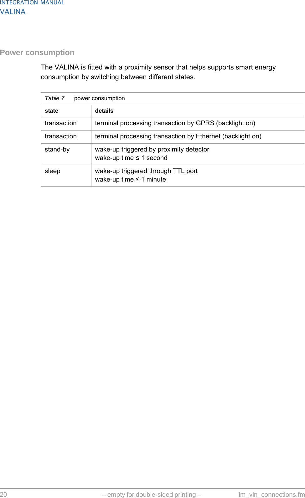
Worldline n v VAL512 NFC Payment terminal User Manual VALINA IntegrationManual
Worldline s.a./n.v. NFC Payment terminal VALINA IntegrationManual
Contents
- 1. use manual appendix with statements
- 2. user manual part2
- 3. user manual part1
user manual part1
![unrestricted iiiim_valinaLOF.fm document release 0.1 last updated 6/6/16INTEGRATION MANUALVALINAFiguresFigure 1. VALINA – front view................................................................................................4Figure 2. VALINA – back view ............................................................................................... 4Figure 3. Aligning VALINA terminal and mounting plate........................................................9Figure 4. Power connections – Microfit (left), MDB (right) ................................................... 10Figure 5. Cable ties for VALINA...........................................................................................11Figure 6. VALINA with TELECOM cover [1] in place ...........................................................12Figure 7. Fitting SAM cards ................................................................................................. 13Figure 8. Inserting the micro SD card ..................................................................................14Figure 9. Inserting optional communications board in VALINA............................................15Figure 10. Fitting the SIM card.............................................................................................15Figure 11. Power supply / data connectors on the VALINA.................................................17Figure 12. JTAG/DEBUG port..............................................................................................21Figure 13. Cleaning card for chip-card reader (sliding brush)..............................................23Figure 14. Cleaning card for magstripe-card reader............................................................ 23Figure 15. Internal mounting details for VALINA..................................................................28Figure 16. Minimum required space (from EVA Specs)....................................................... 28](https://usermanual.wiki/Worldline-n-v/VAL512.user-manual-part1/User-Guide-3274832-Page-5.png)


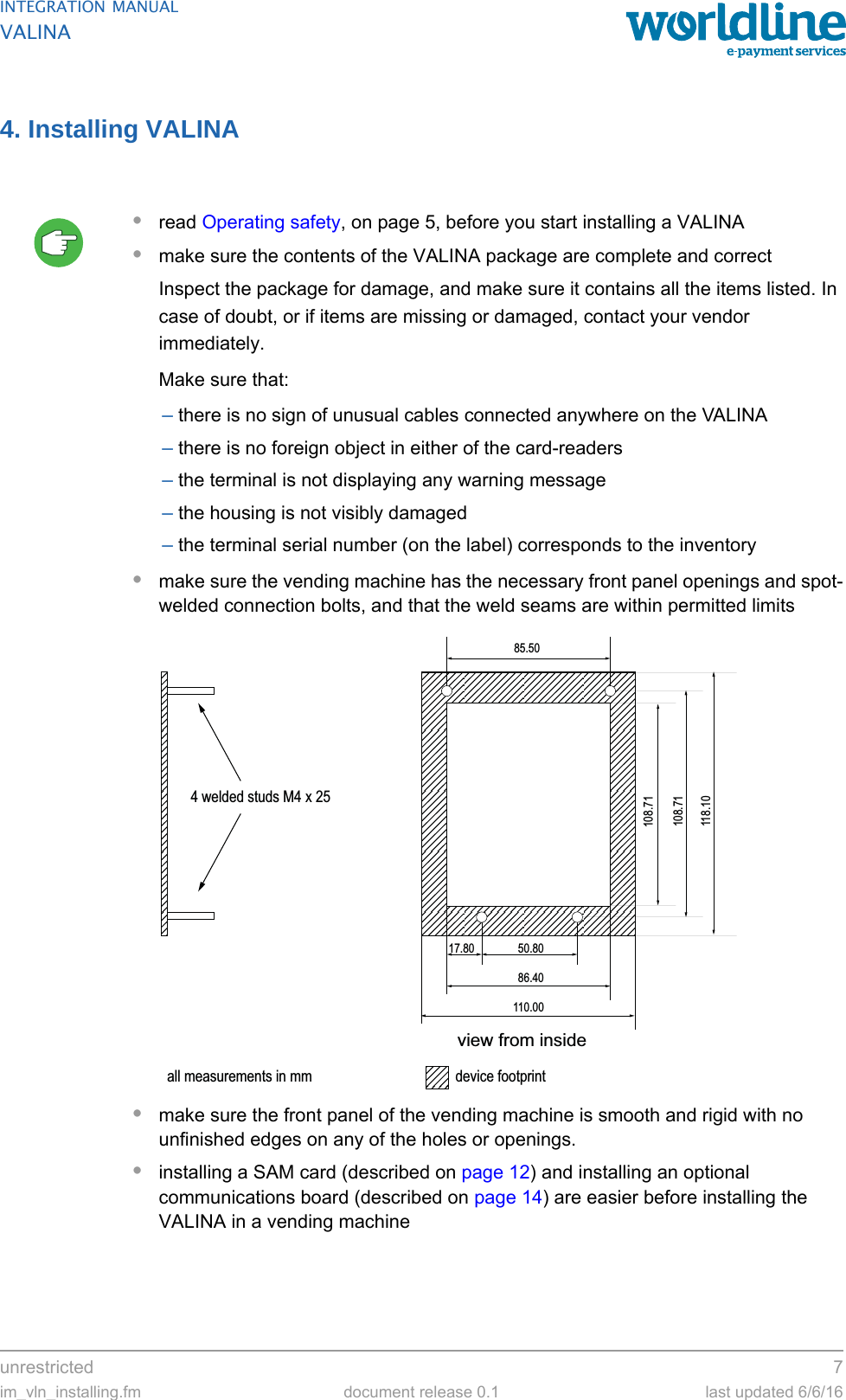
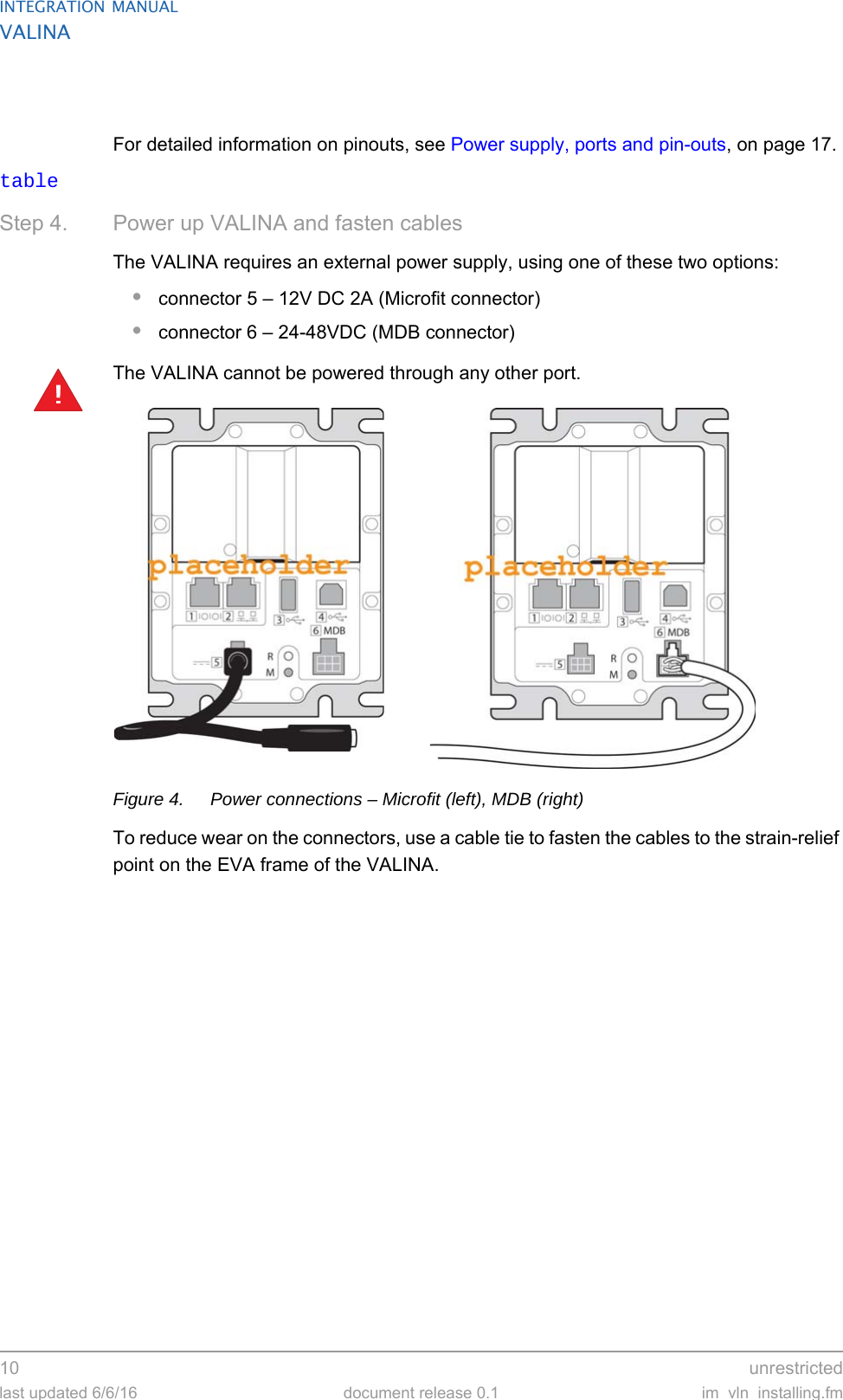
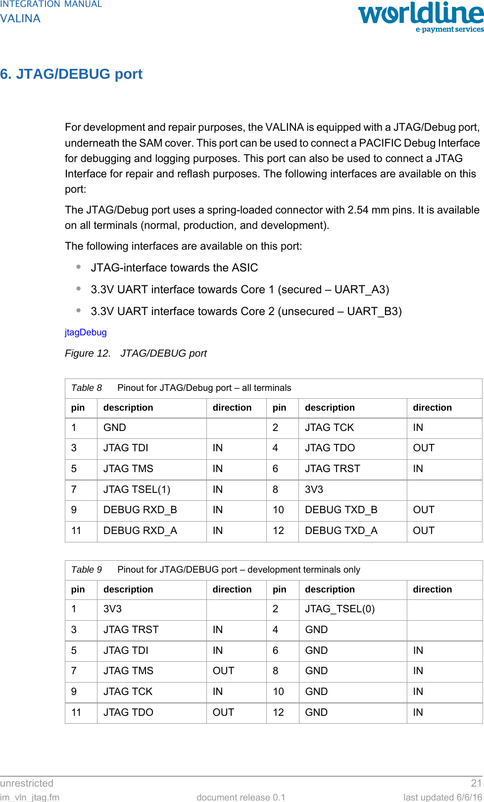
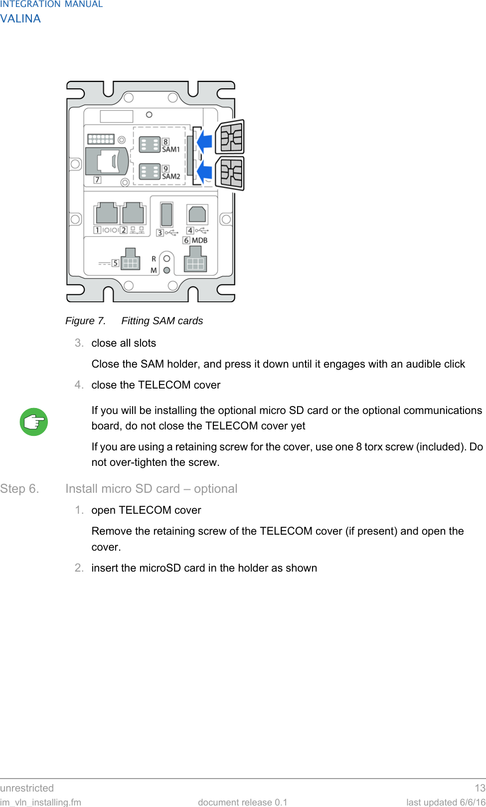
![INTEGRATION MANUALVALINA12 unrestrictedlast updated 6/6/16 document release 0.1 im_vln_installing.fmStep 5. Install SAM card – optionalThe VALINA has two type ID 0 SAM slots.•install any SAM card before installing the optional communications board•install both SAM card and communications board before installing the VALINA in the vending machine.1. open TELECOM coverRemove the retaining screw of the TELECOM cover (if present) and open the cover.Figure 6. VALINA with TELECOM cover [1] in place2. open SAM holder and insert SAM cardOpen the SAM holder (with the two bar-code labels on) and insert one or two SAM cards as shown. Make sure the card is completely inserted.](https://usermanual.wiki/Worldline-n-v/VAL512.user-manual-part1/User-Guide-3274832-Page-18.png)

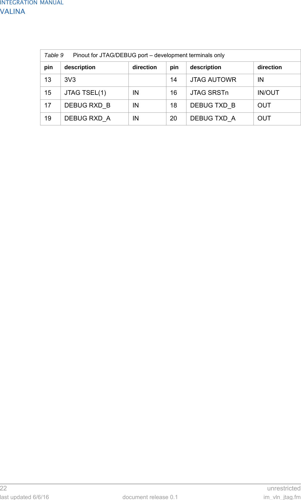
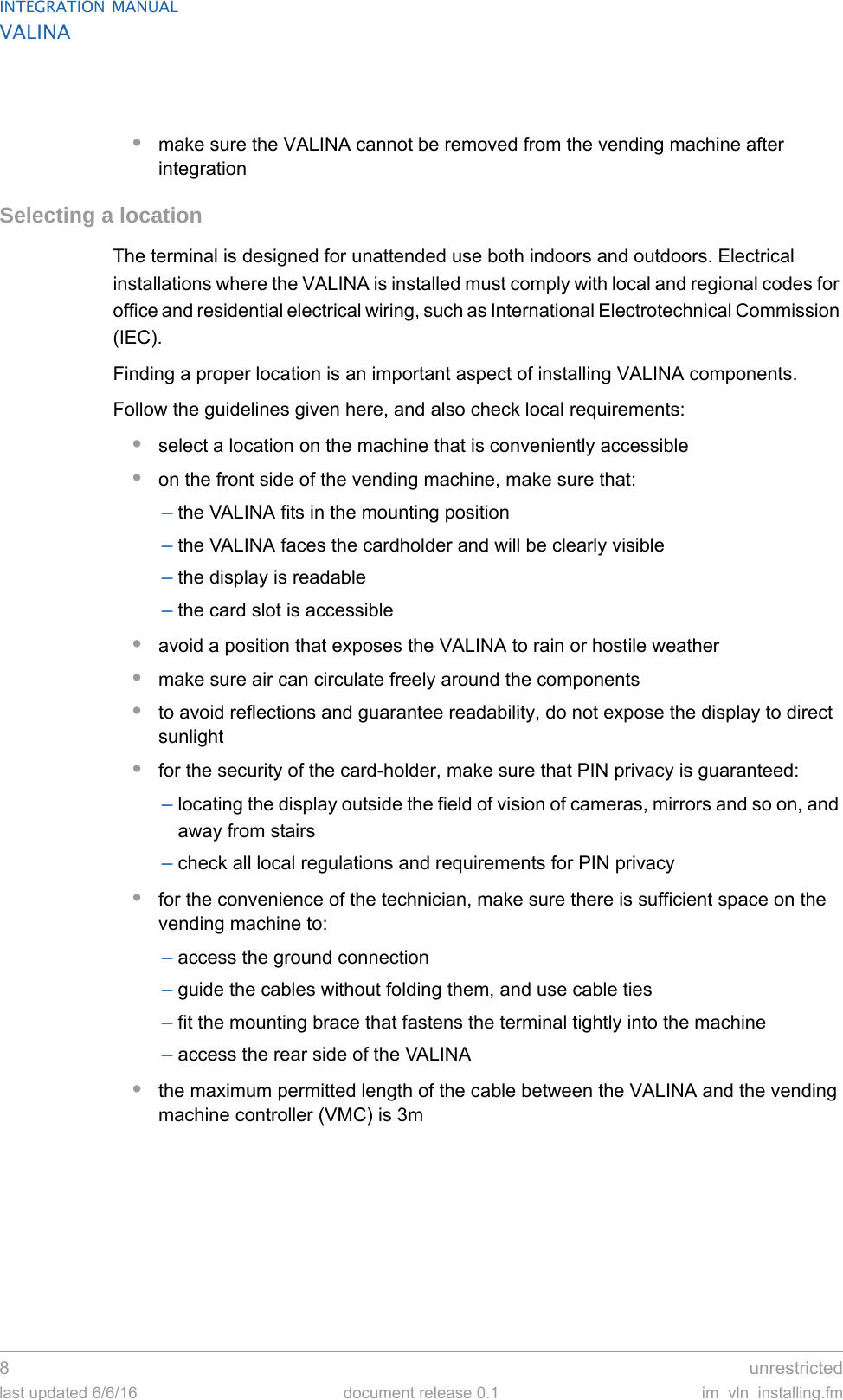
![unrestricted 17im_vln_connections.fm document release 0.1 last updated 6/6/16INTEGRATION MANUALVALINA5. Power supply, ports and pin-outsThis chapter describes the power supply / data connectors on the VALINA.Figure 11. Power supply / data connectors on the VALINAPower supplyThe VALINA is powered from an external power adaptor through port 5 (TTL) or port 6 (MDB).•the TTL interface is a surface-mounted, dual-row, 6 circuit connector (Molex Microfit connector) with a press-fit metal retention clip•the MDB interface is …Table 1 Pinout for Microfit 43045-0616 interfacepin description pin description1 Vcc in 4 IN [1]2 GND 5 IN [2]3 IN [0] 6 OUT [0]Table 2 Pinout for MDB interfacepin description pin description1425](https://usermanual.wiki/Worldline-n-v/VAL512.user-manual-part1/User-Guide-3274832-Page-23.png)
![INTEGRATION MANUALVALINA18 unrestrictedlast updated 6/6/16 document release 0.1 im_vln_connections.fmThe VALINA is CE certified in combination with the Powertech ADS 0271-B adaptor. If any other power supply is used, the distributor is responsible for compliance with local safety requirements and regulations.USB-B (device) interfaceThe VALINA is fitted with a USB 2.0 Full Speed (up to 480 MBit/sec) device interface, which can be used to connect to ePOS equipment or a PC and to perform keyloading.The necessary USB-driver is included in recent installation packages of most operating systems (Windows, MacOS and Linux). If the driver is not available, contact your vendor.VALINA cannot be powered through the USB device interface: it always needs an external power supply.Ethernet 10/100 MbitThe VALINA has a standard 10/100 megabit Ethernet interface, using an RJ45 (8p/8c) connector.VALINA cannot be powered through the Ethernet interface.36Table 2 Pinout for MDB interface!Table 3 Pinout for USB-B interface pin description direction1 VCC (5V) VALINA IN2 D- VALINA IN/OUT3 D+ VALINA IN/OUT4GND!Table 4 Pinout for Ethernet 10 Mbit connectorpin description direction8HF GND7HF GND6 RX B VALINA [IN] from network5HF GND4HF GND3 RX A VALINA [IN] network2 TX B VALINA [OUT] network1 TX A VALINA [OUT] network](https://usermanual.wiki/Worldline-n-v/VAL512.user-manual-part1/User-Guide-3274832-Page-24.png)
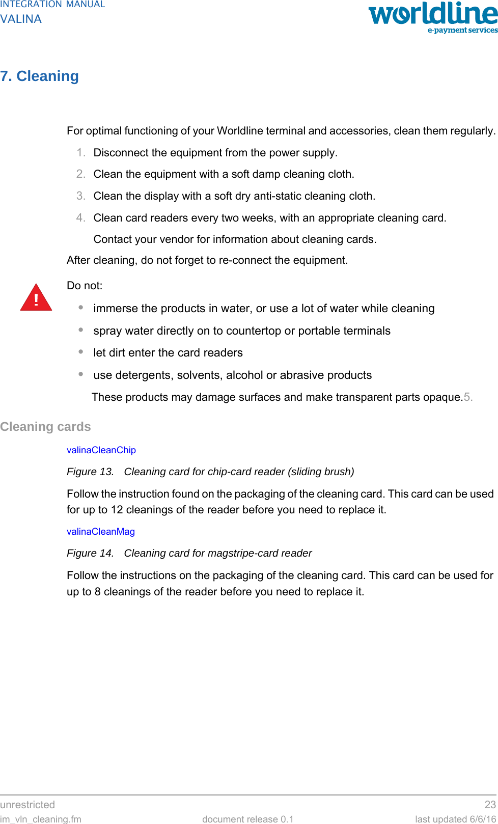
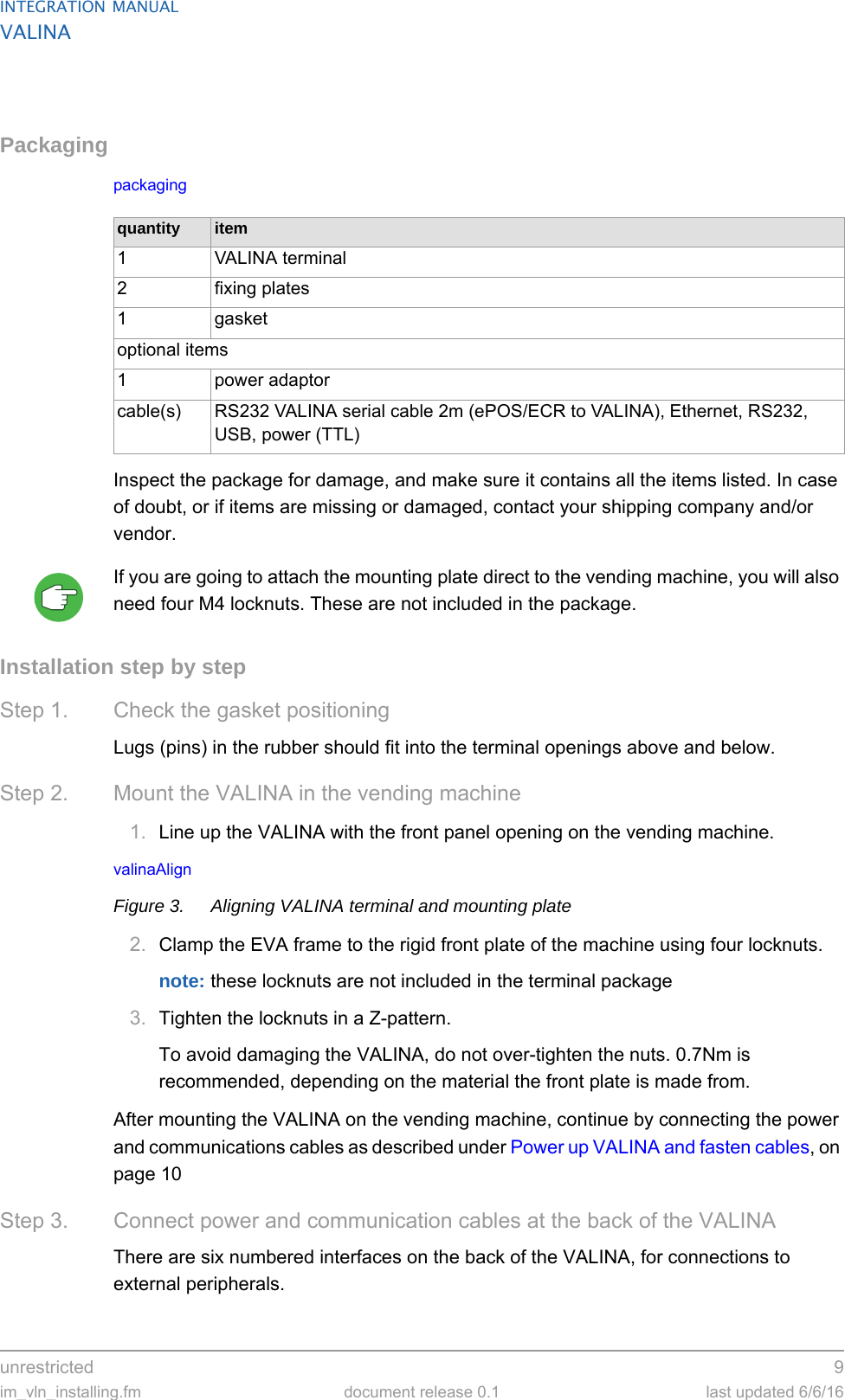
![unrestricted 19im_vln_connections.fm document release 0.1 last updated 6/6/16INTEGRATION MANUALVALINARS-232 interfaceThe VALINA has one RS-232 interface with RTS/CTS flow-control, for connecting to peripherals such as a vending-machine controller, ePOS equipment or a printer.VALINA cannot be powered through the RS-232 interface.The interface allows connections up to 230,400bps and is fitted with an 8p RJ45 connector with the following pinout.USB-A (host) interfaceThe VALINA is fitted with a USB 2.0 full speed (up to 480 MBit/sec) host interface, which can be used to connect to a USB stick or other storage device.VALINA cannot be powered through the USB host interface: it always needs an external power supply.The pin-out of the USB host interface is as follows:Vending machine controllerThe VALINA communicates with the Vending Machine Controller (VMC) through RJ45 connector 3 (RS-232) or through TTL connector 6.!Table 5 Pinout for RS-232 interfacepin description direction8VCC VALINA [IN]7VCC VALINA [IN]6TX VALINA [OUT]5RX VALINA [IN]4CTS VALINA [IN]3RTS VALINA [OUT]2GND1GND!Table 6 Pinout for USB host interfacepin description direction1 VCC (5V) VALINA OUT2 D- VALINA IN/OUT3 D+ VALINA IN/OUT4GND](https://usermanual.wiki/Worldline-n-v/VAL512.user-manual-part1/User-Guide-3274832-Page-25.png)