Worthdata LT701 RF Terminal User Manual
Worthdata Inc RF Terminal
UserManual.wiki
>
Worthdata
>
LT701 User Manual
User Manual
Navigation menu
Upload a User Manual
Namespaces
Wiki Guide
HTML
PDF
Info
Views
User Manual
Discussion / Help
Navigation

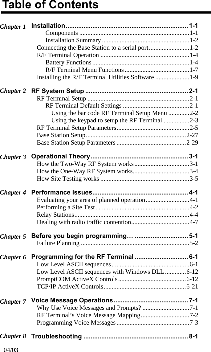
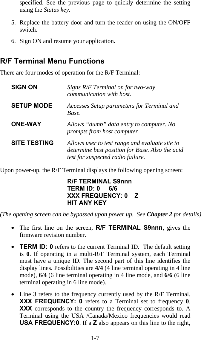
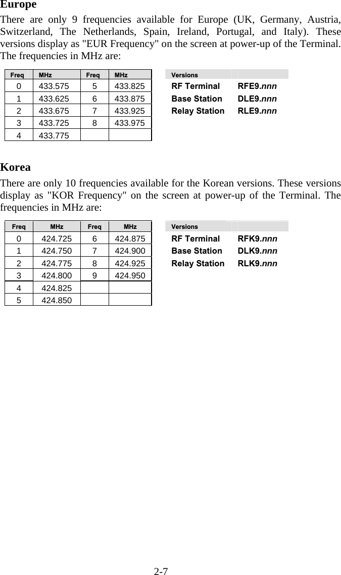
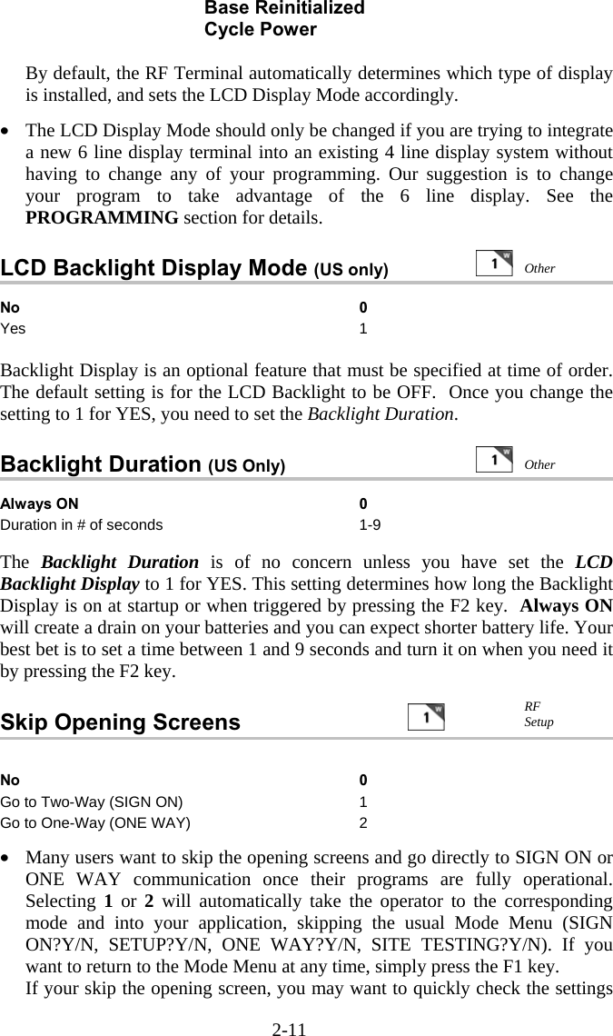
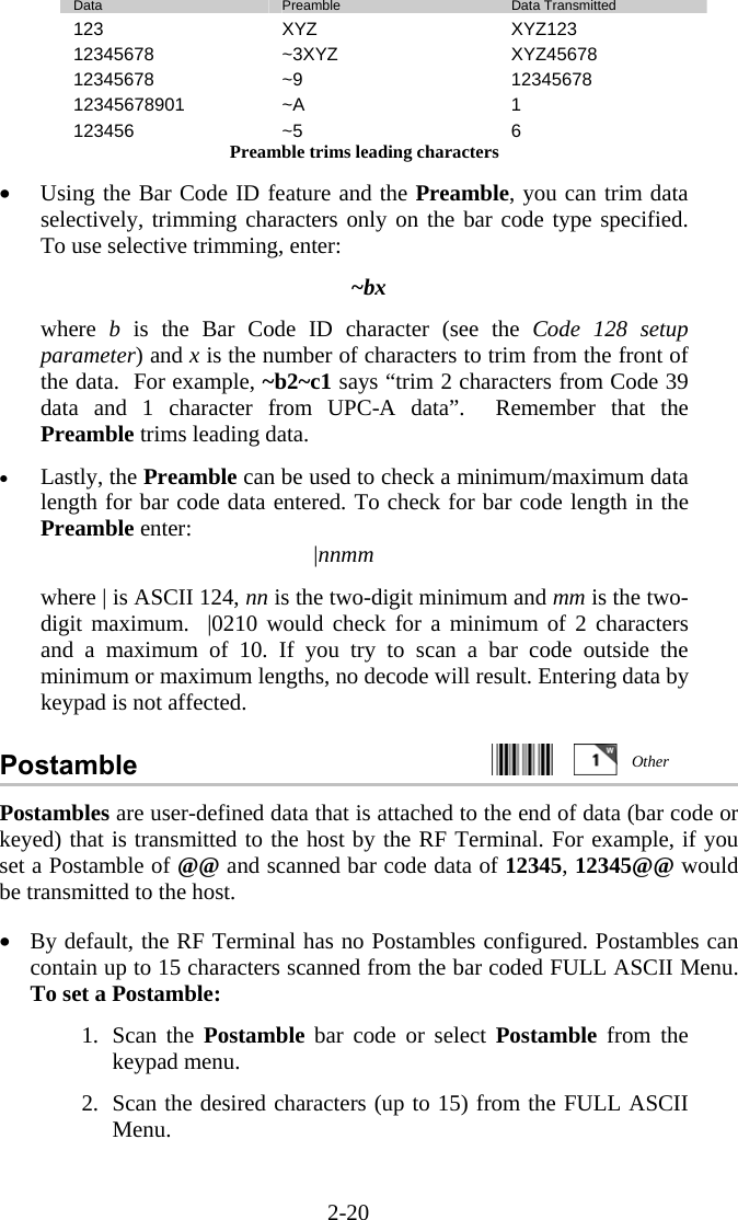
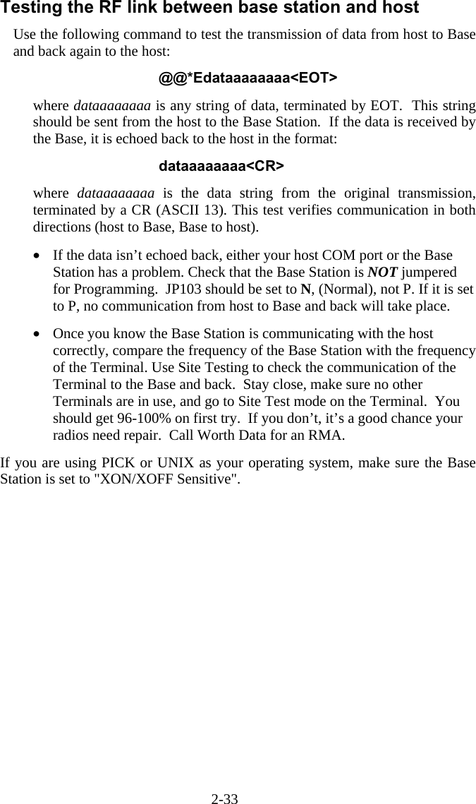
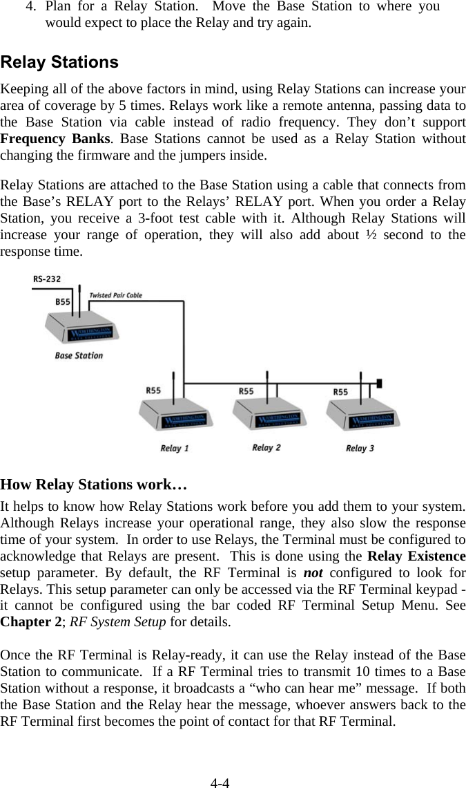
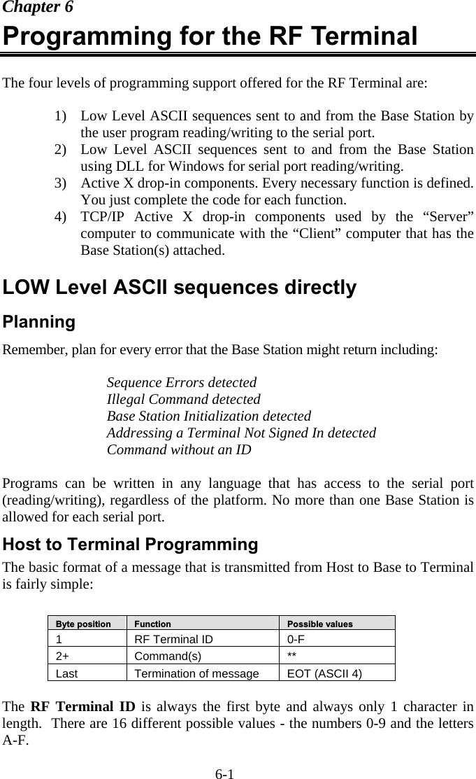
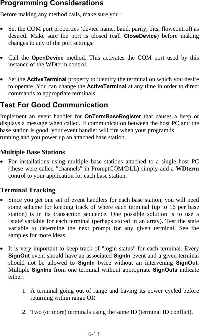
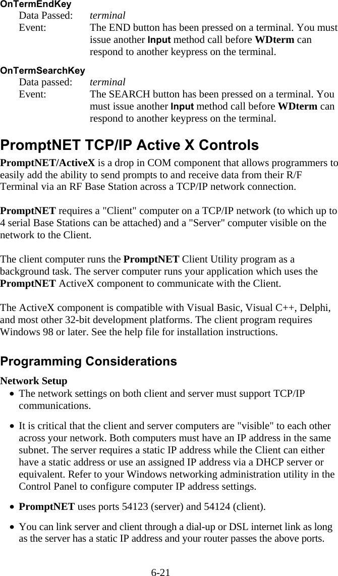
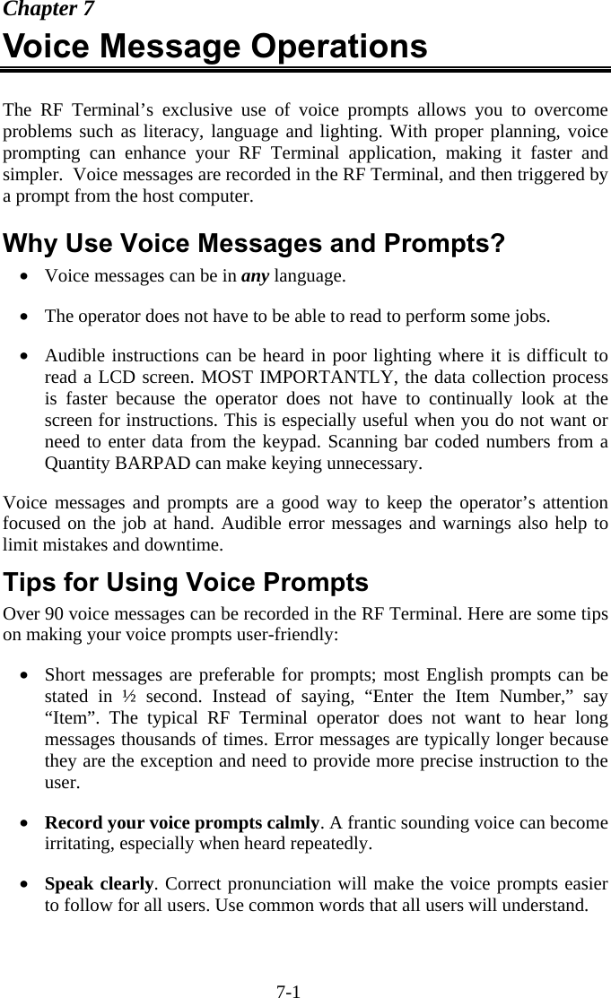
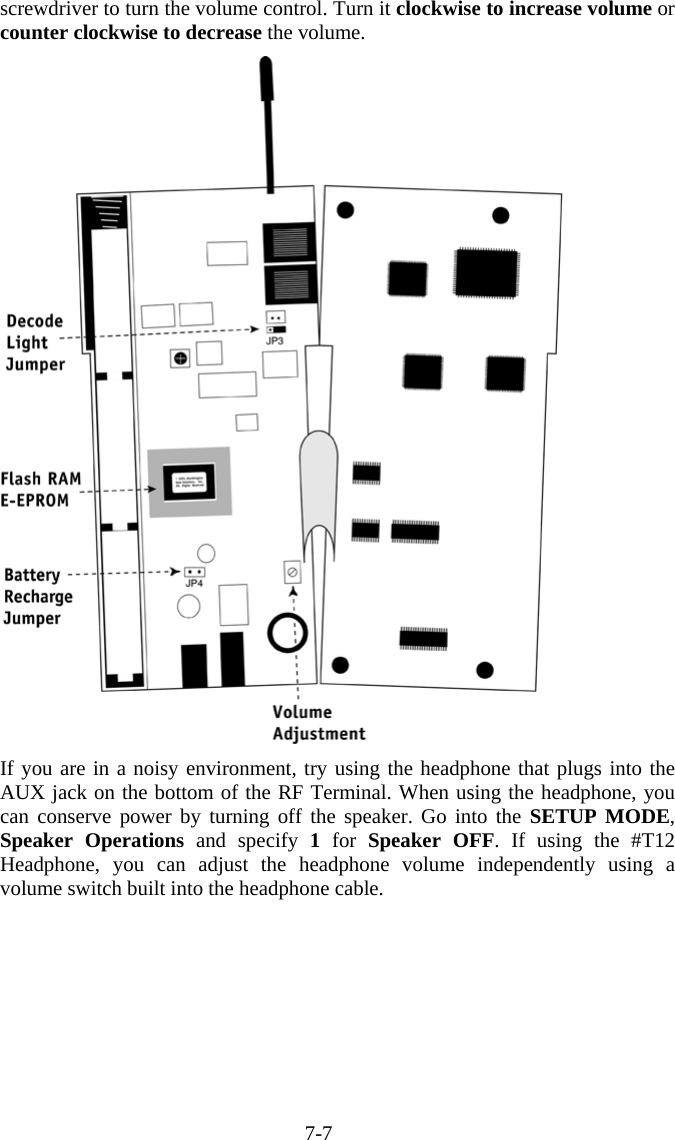
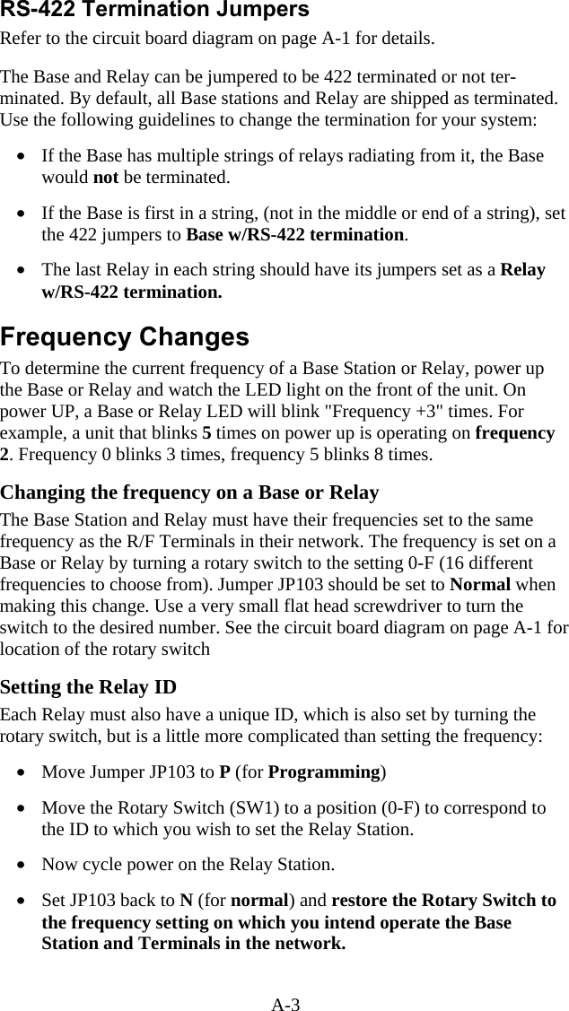
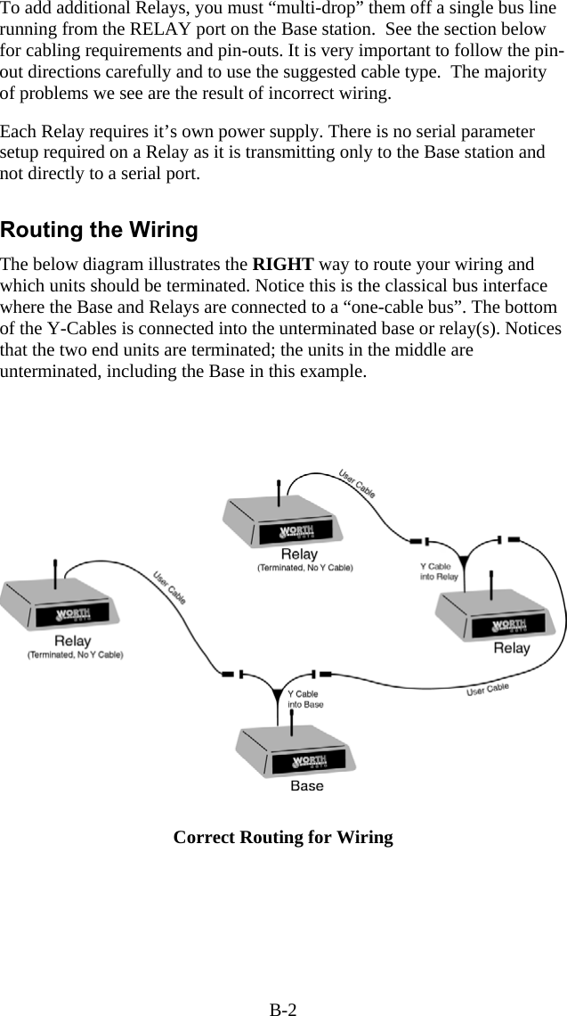
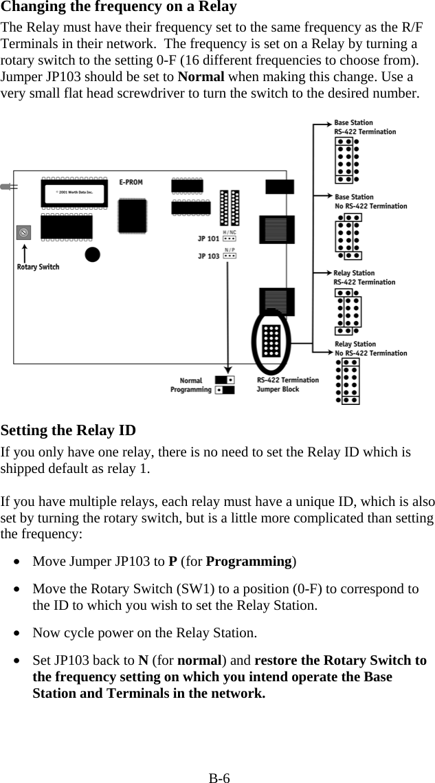
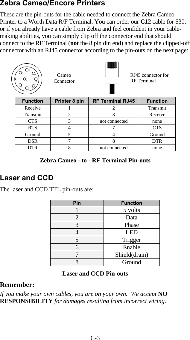
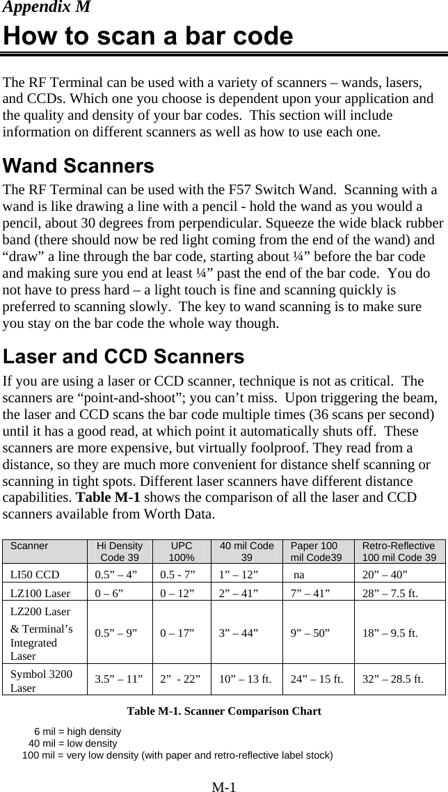
![1-8 the terminal is capable of supporting the Zebra Cameo and Encore portable printers. To move on to the first menu item, press any key on the R/F Terminal keypad. The display now reads: SIGN ON? KEY [YES/NO]?_ • Press the YES key to SIGN ON to a two-way communication host computer program through the Base station. • Press NO to move on to the next menu item: SETUP MODE? KEY [YES/NO]?_ • Pressing YES prompts for a password to enter the Setup Mode for the R/F Terminal or Base station. • Press NO to move on to: ONE-WAY? KEY [YES/NO]?_ • Press YES to enter ONE-WAY mode. ONE-WAY mode allows the R/F Terminal to transmit data to the host computer without prompting from the host computer program – we call this “dumb” data entry. ONE-WAY mode is also useful for demos, as it does not require any interaction from the host computer. • Press NO to go to: SITE TESTING? KEY [YES/NO]?_ • Press YES to enter SITE TESTING. SITE TESTING is an excellent way to assess your R/F communication in any area. It can help you determine the best place to locate your Base station for maximum R/F performance as well as troubleshoot problems that may relate to range or interference. • Press NO to loop back to the SIGN ON? prompt. You can back-out of any mode or prompt by pressing the F1 key. For example, if you press YES at the SETUP MODE? prompt but really meant to press NO, press the F1 key to take you back to the menu. The F1 key on the R/F Terminal keypad works like the ESC key on the PC – it will usually get you out and back to the previous step. You can use the F1 key to exit and SIGN OUT when using a Two-Way communication program running on the host computer.](https://usermanual.wiki/Worthdata/LT701/User-Guide-377201-Page-11.png)
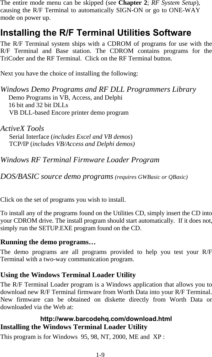
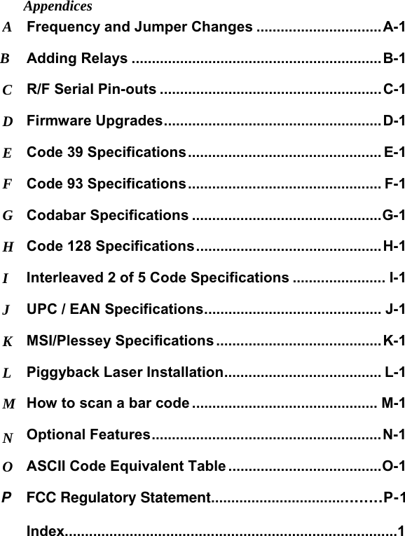
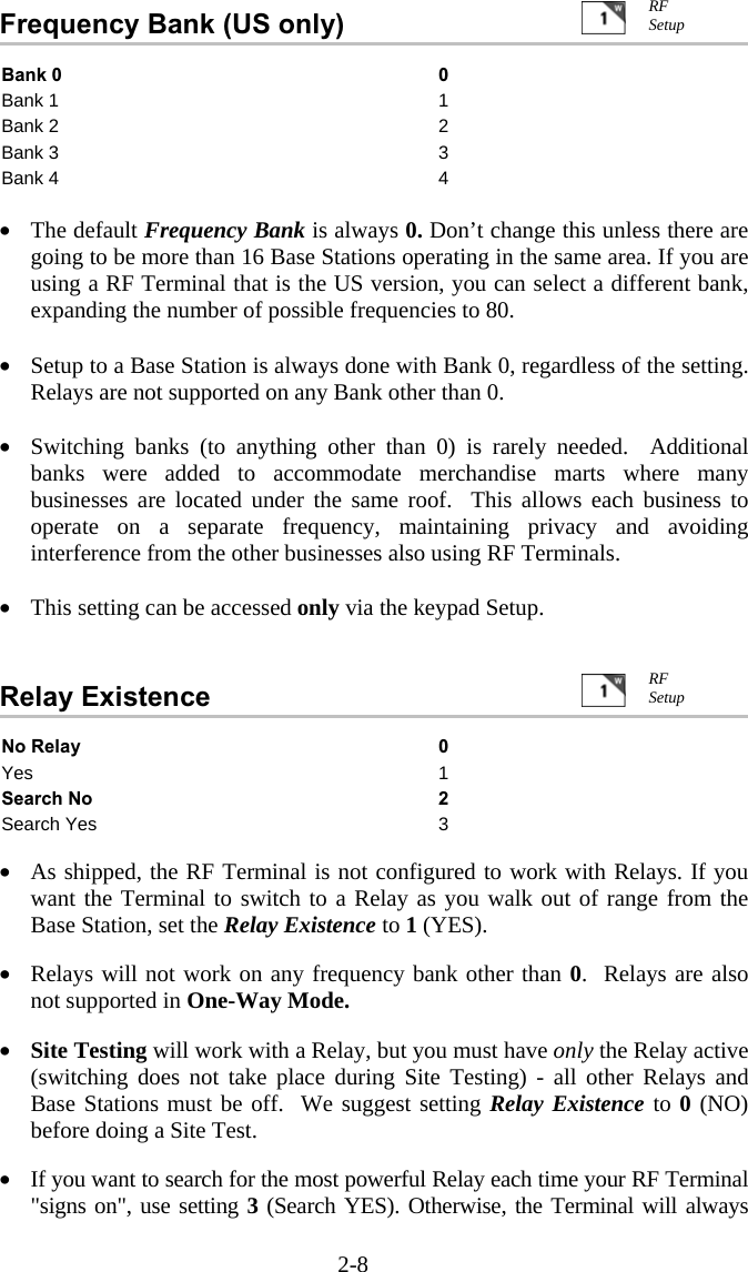
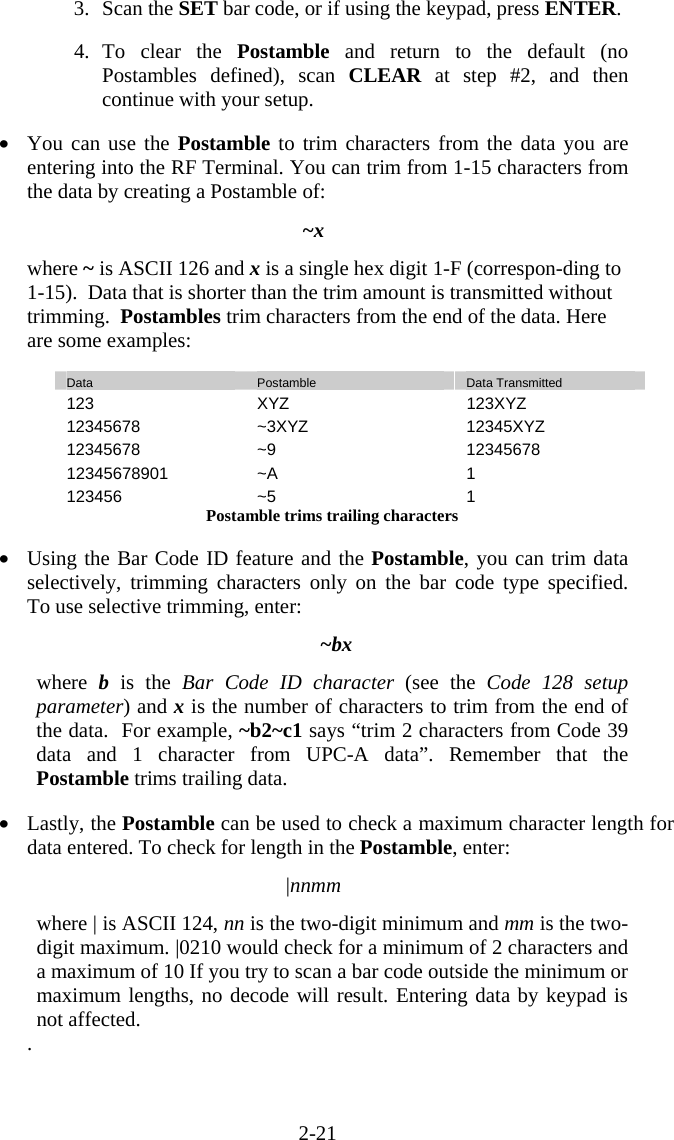
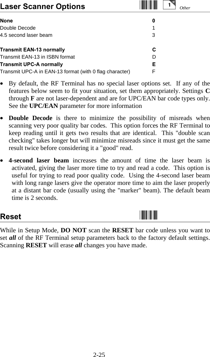
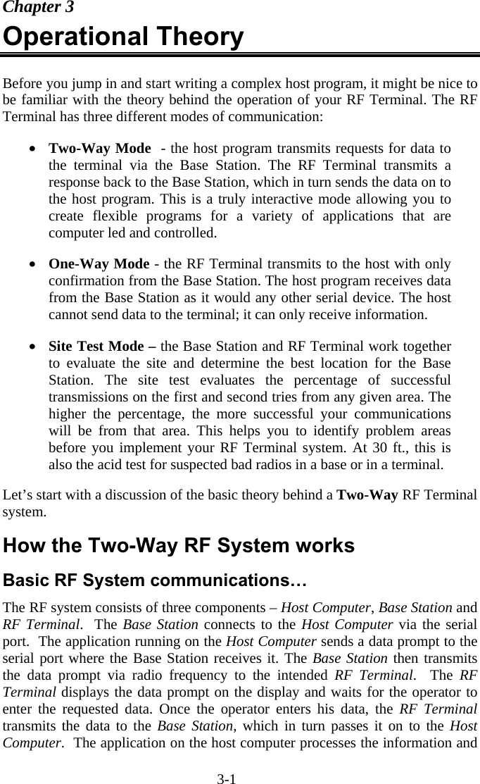
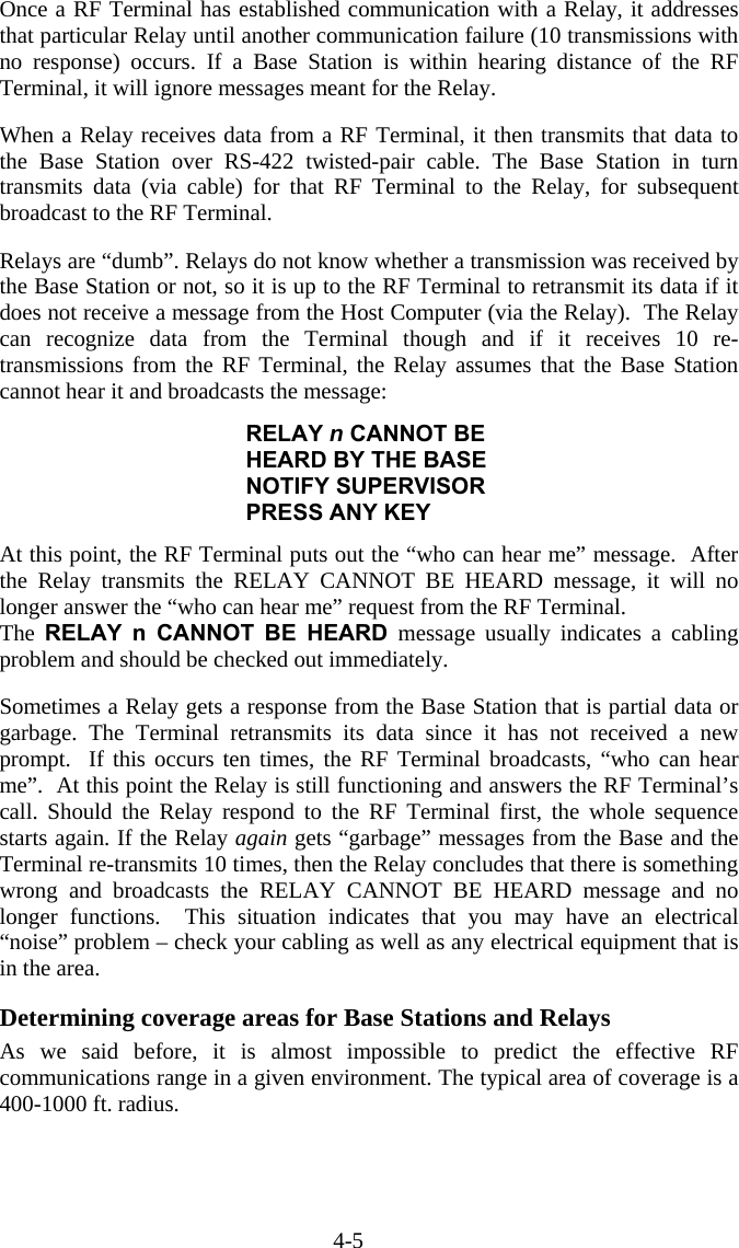
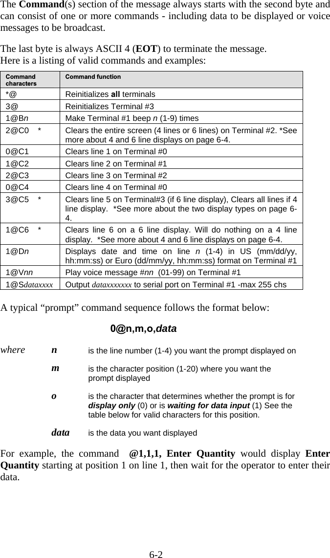
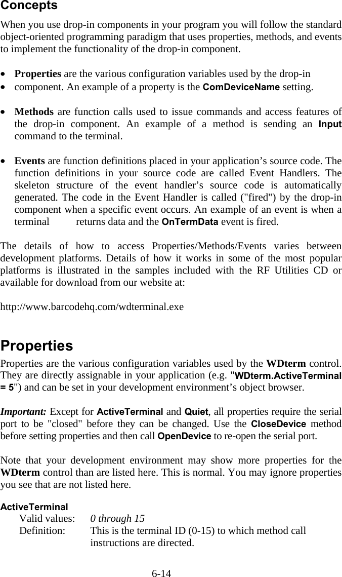
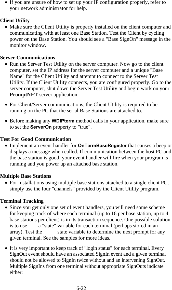
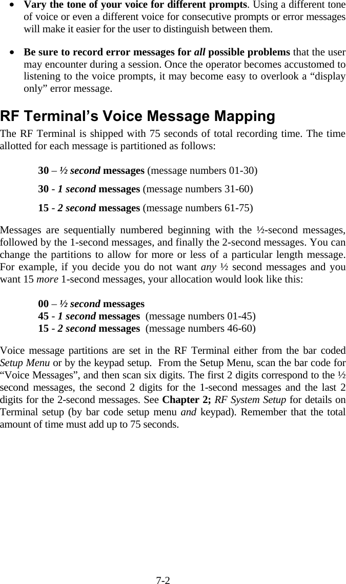
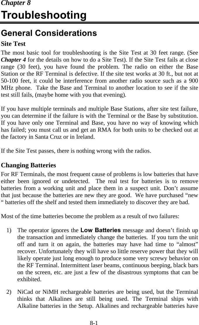
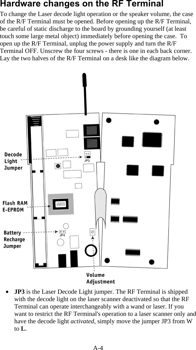
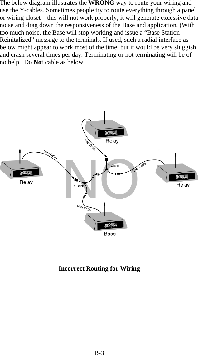
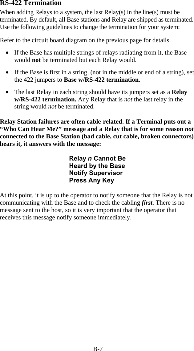
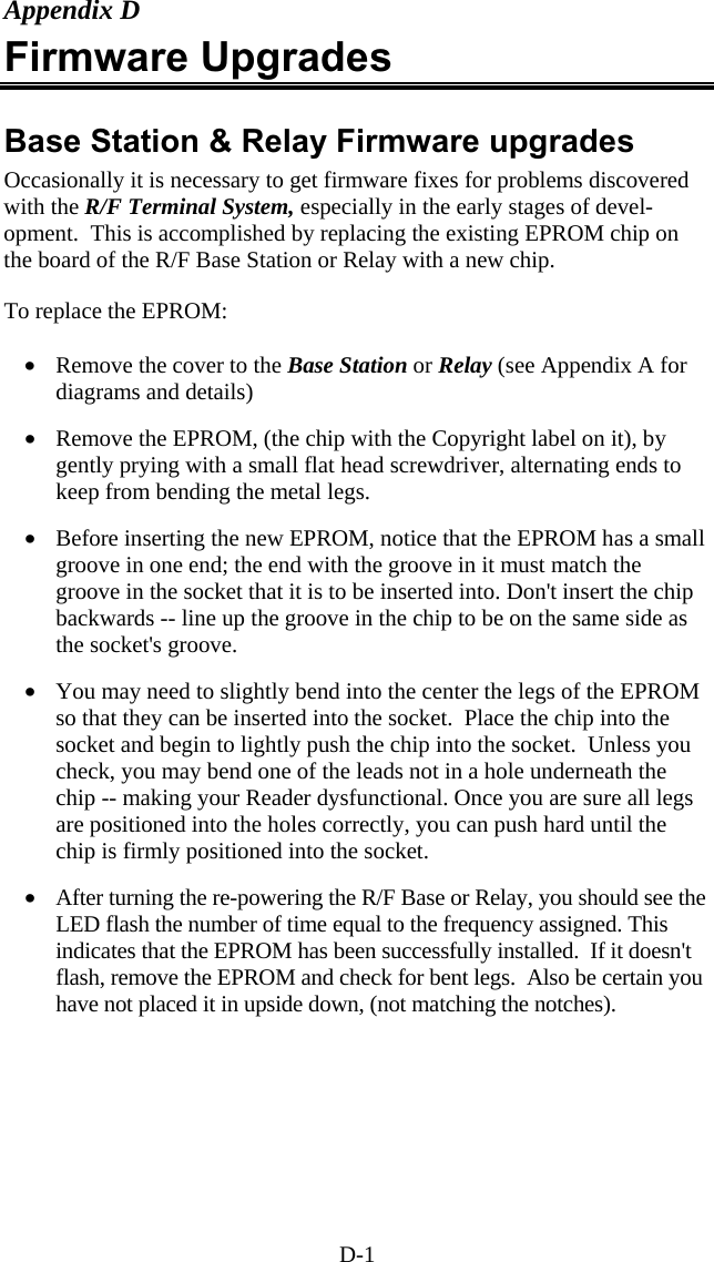
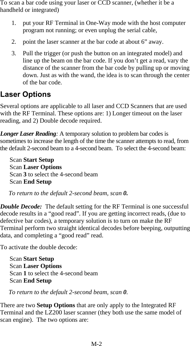
![2-3 If you are using a Laser Scanner to setup the RF Terminal, the beam will often cover more than one bar code. Cover any adjacent bar codes before scanning, and then check the RF Terminal display to make sure the correct setting was entered. Using the keypad to setup the RF Terminal The RF Terminal can be setup via the Terminals' keypad by entering Setup Mode from the menu. Turn on the Terminal and press any key. You should see the SIGN ON? message: SIGN ON? KEY [YES/NO]?_ Press the NO key. The next prompt is the SETUP MODE? prompt: SETUP MODE? KEY [YES/NO]?_ Press the YES key. At this point, the terminal will ask for a password: SETUP MODE PASSWORD?_ Enter WDTRI on the keypad. The next item allows you to choose which item to configure: R/F Terminal------->1 R/F Base Setup--->2 Voice Operations->3 Press 1 to enter the RF Terminal Setup. Now you are in the RF Terminal Setup Menu and can choose from the following options: RF Setup---0 Speaker--4 BarCodes--1 Other------5 RS232-------2 Exit-------F1 Date/Time--3 At this point, choose which group you want to configure. Most of the RF Terminal setup parameters are accessible from the keypad Setup Menu (there are only 2 that are available only from the bar code Setup Menu). Reversely, there are quite a few options that are available only from the keypad Setup. See the beginning of this chapter for a comparison of the two Setup Menus.](https://usermanual.wiki/Worthdata/LT701/User-Guide-377201-Page-16.png)
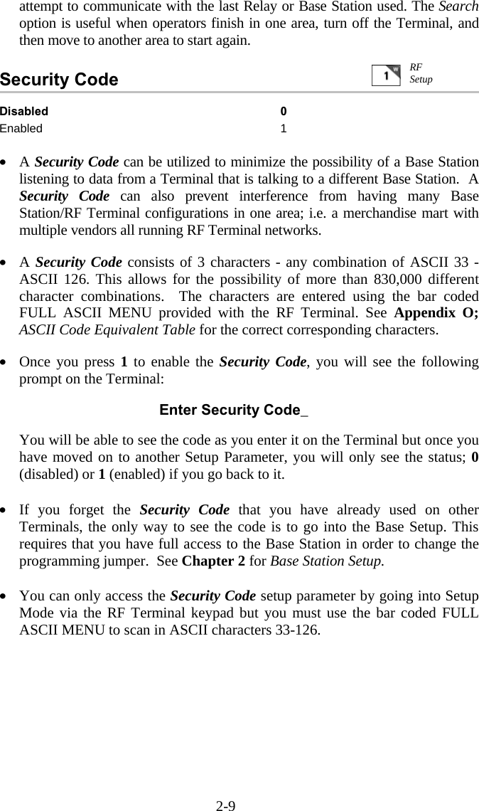

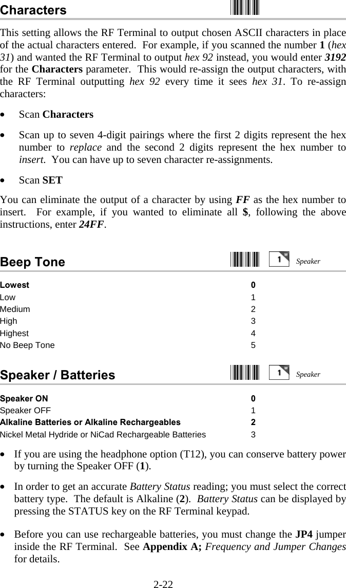
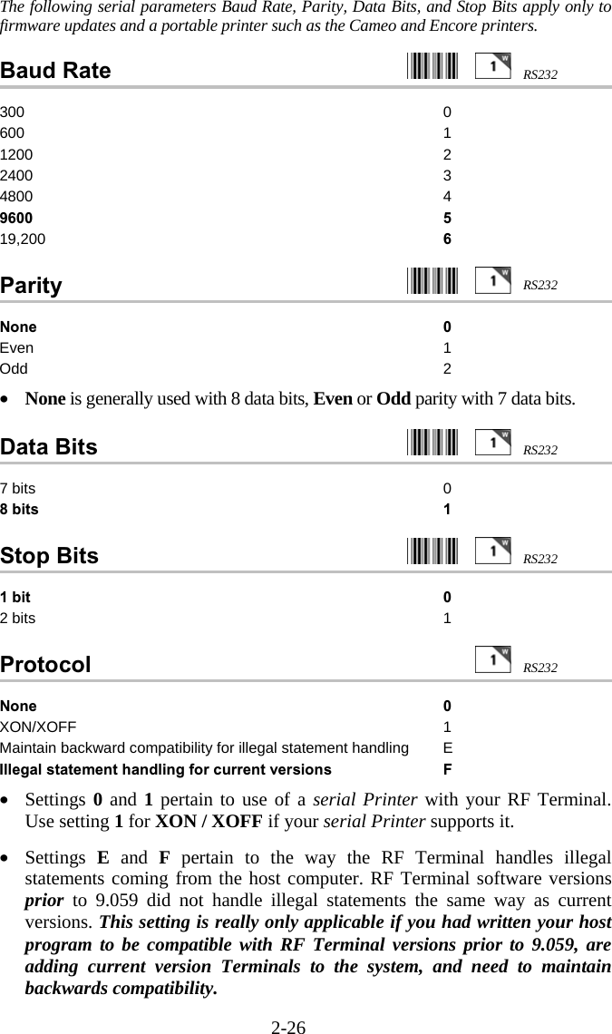
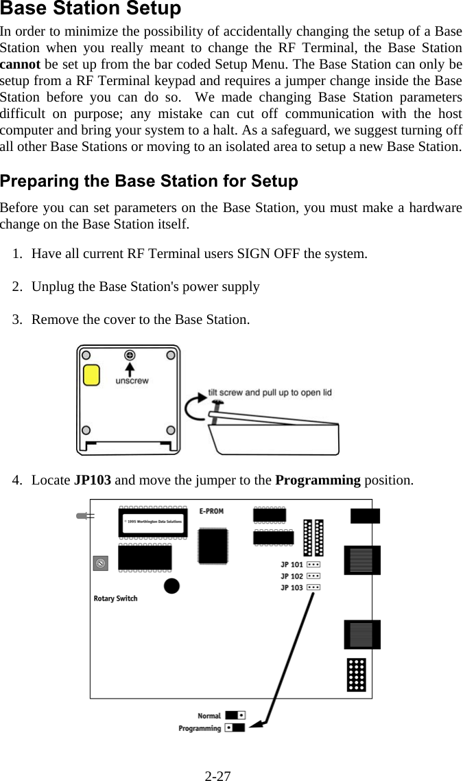
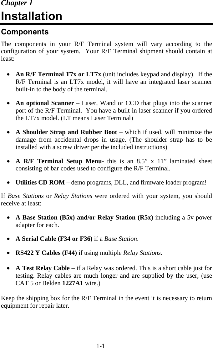
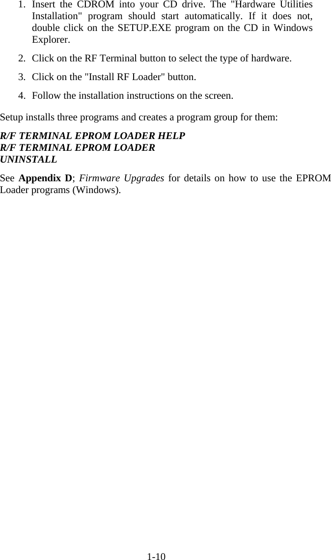
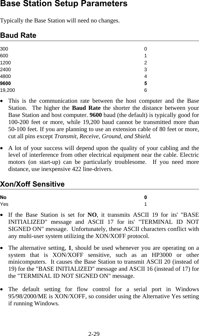
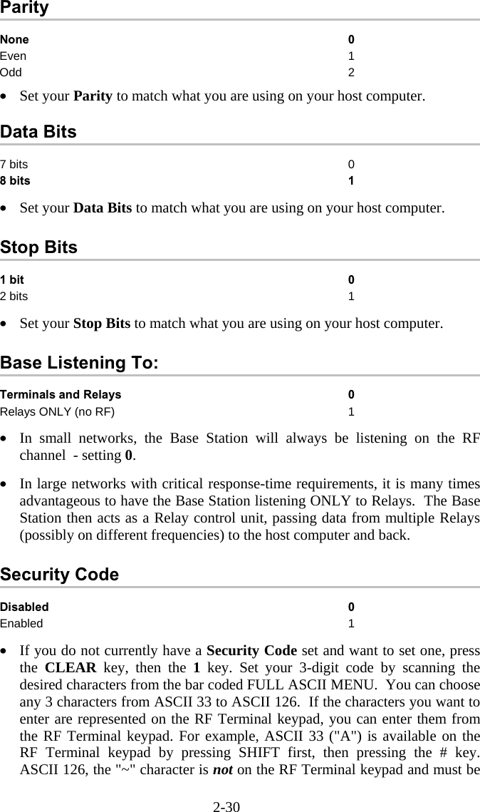
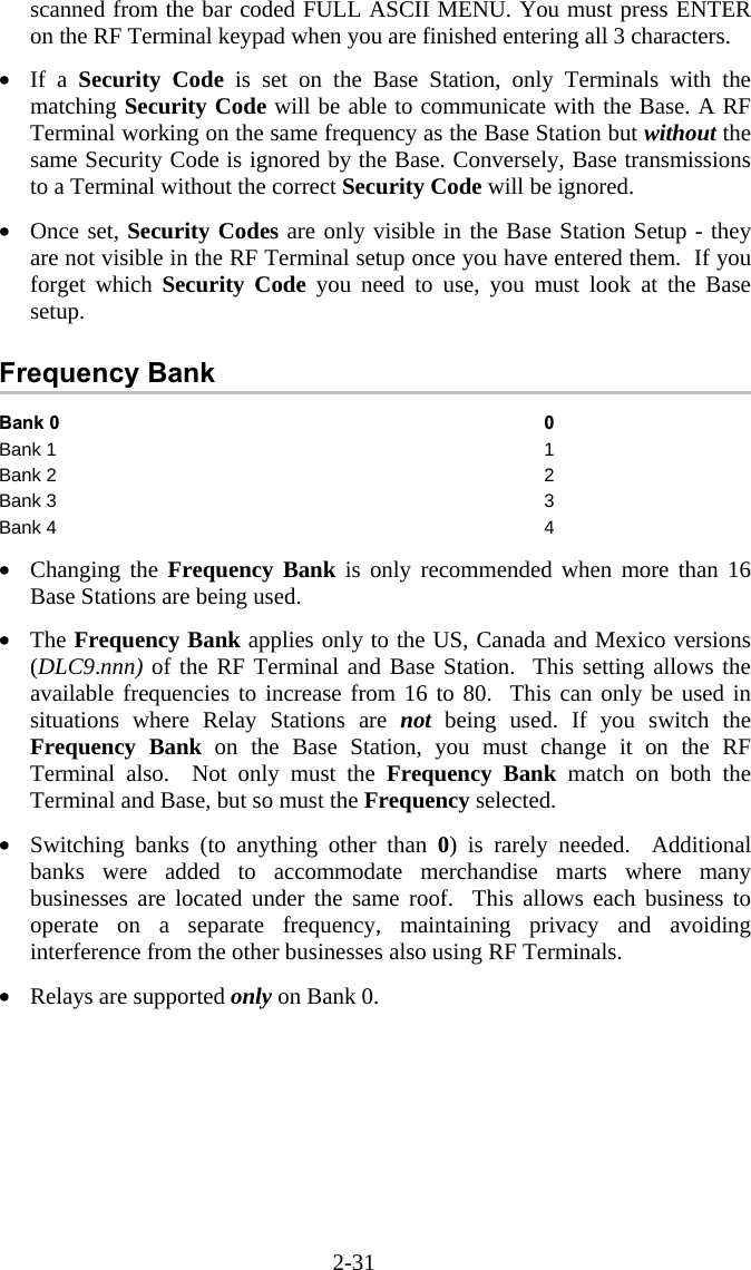
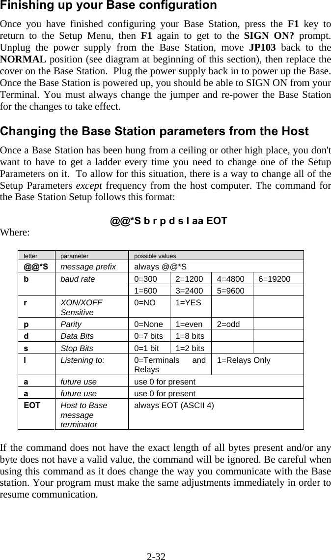
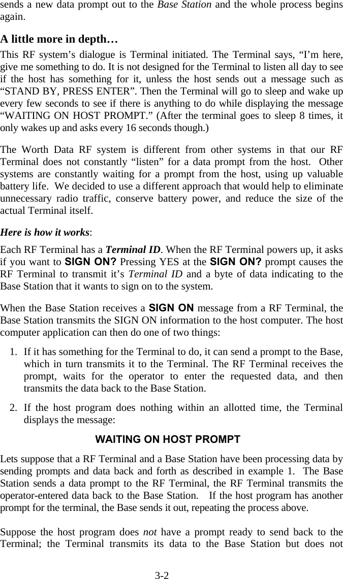
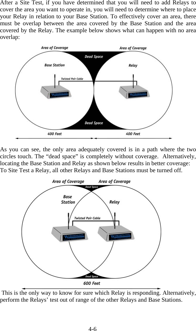
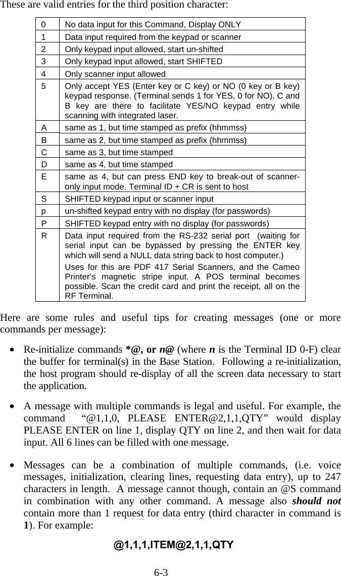
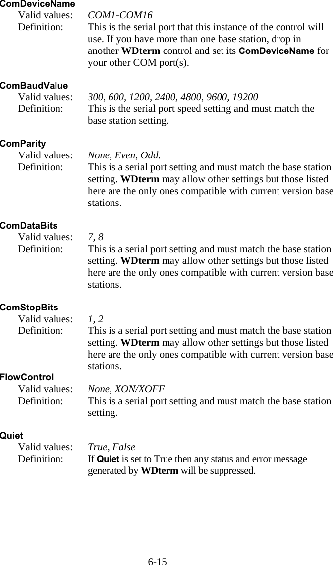
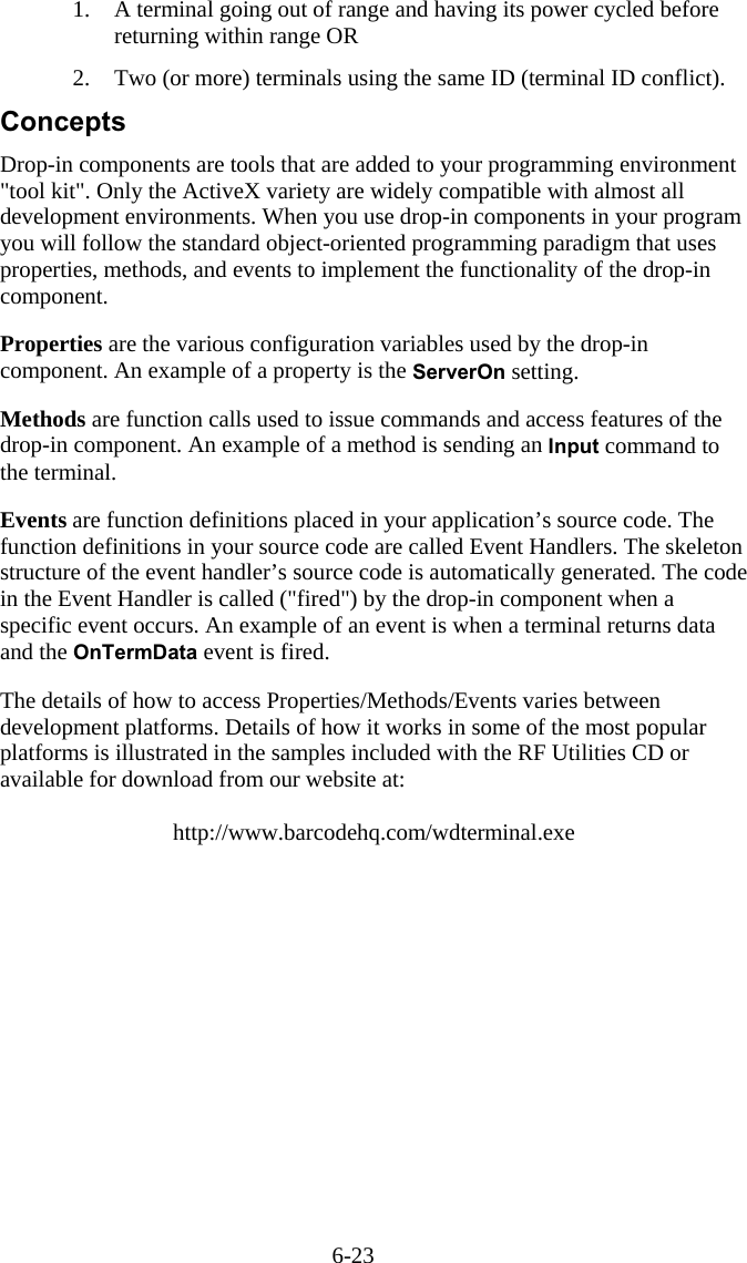
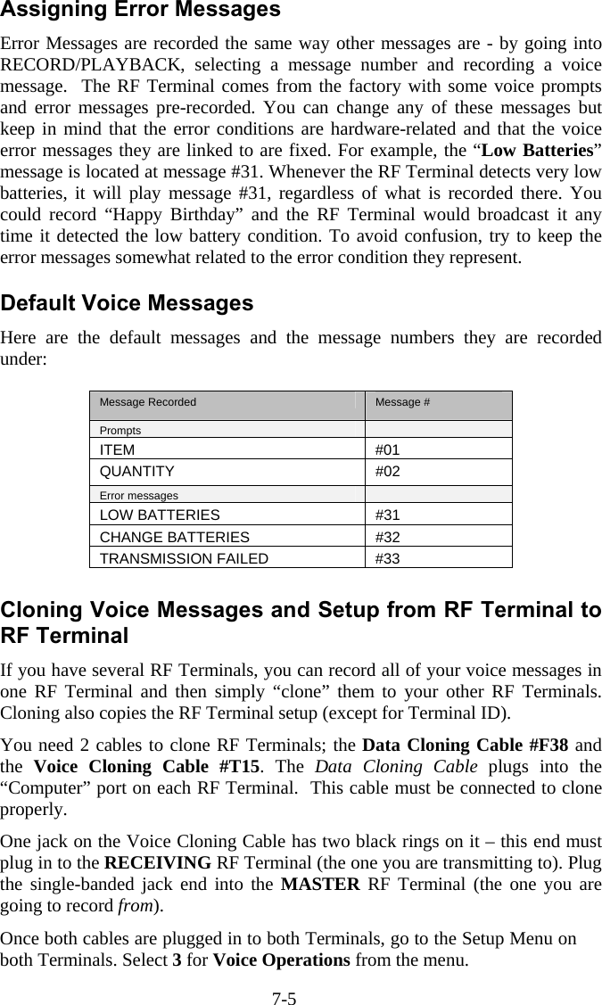
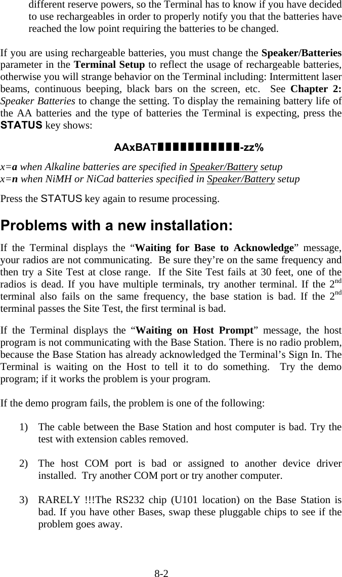
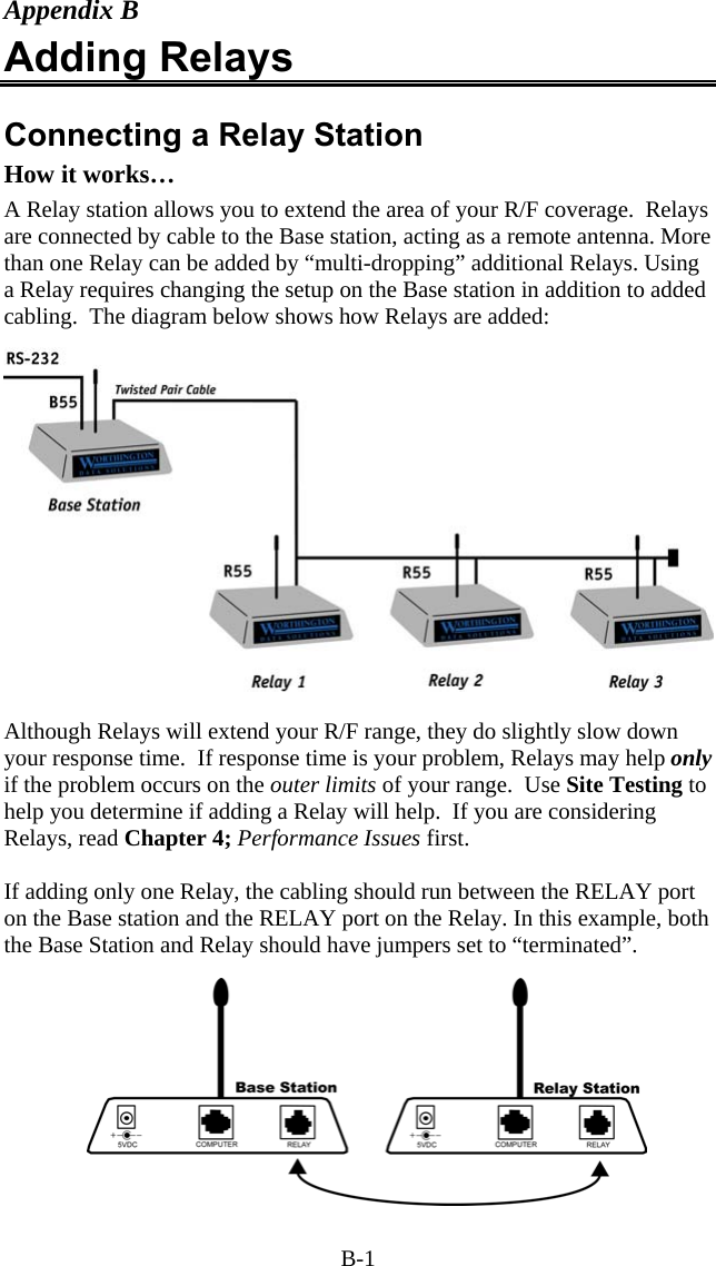
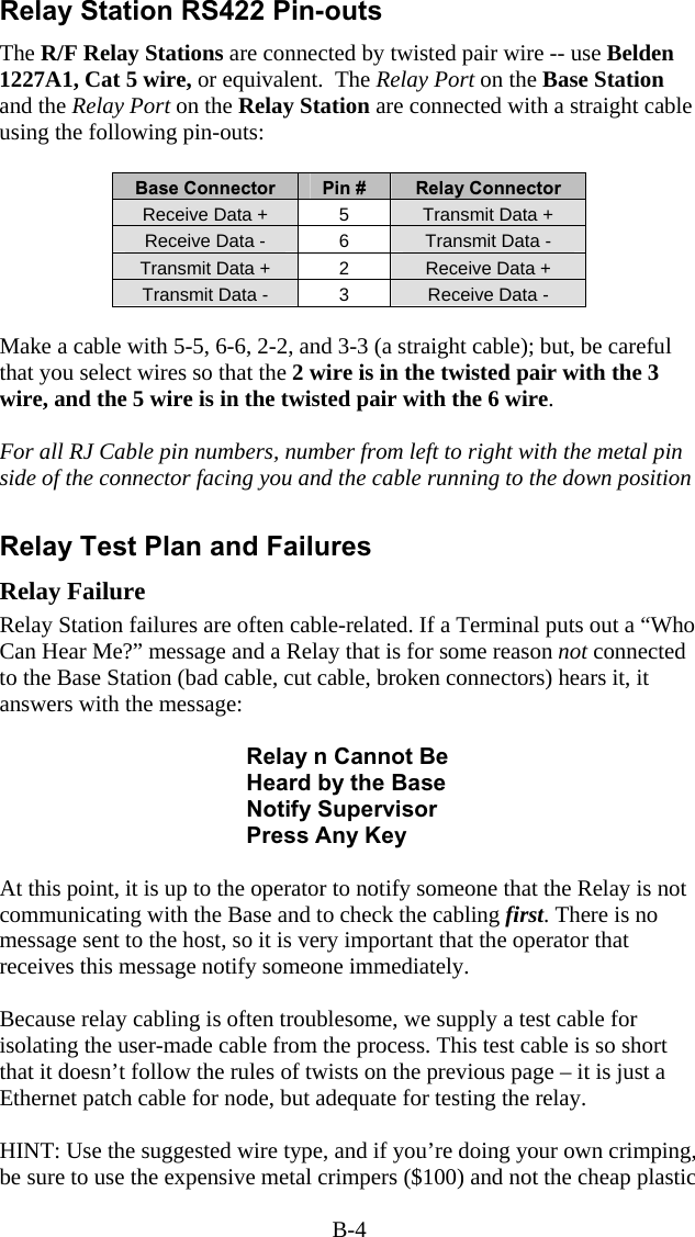
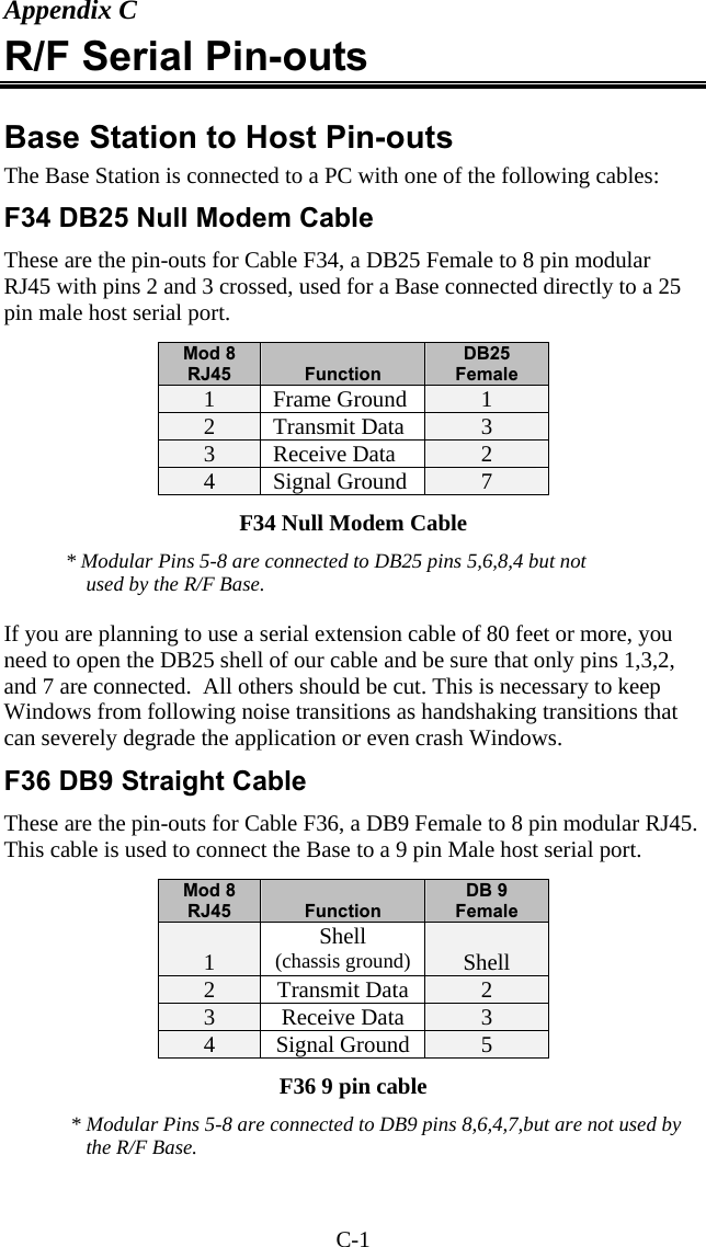
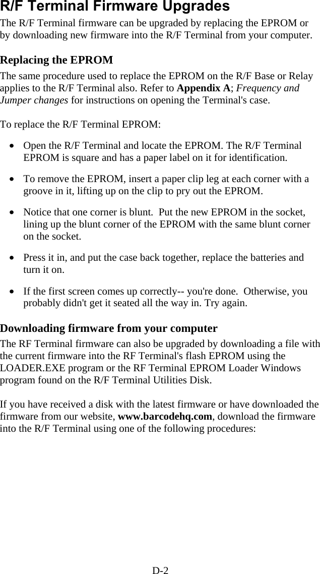
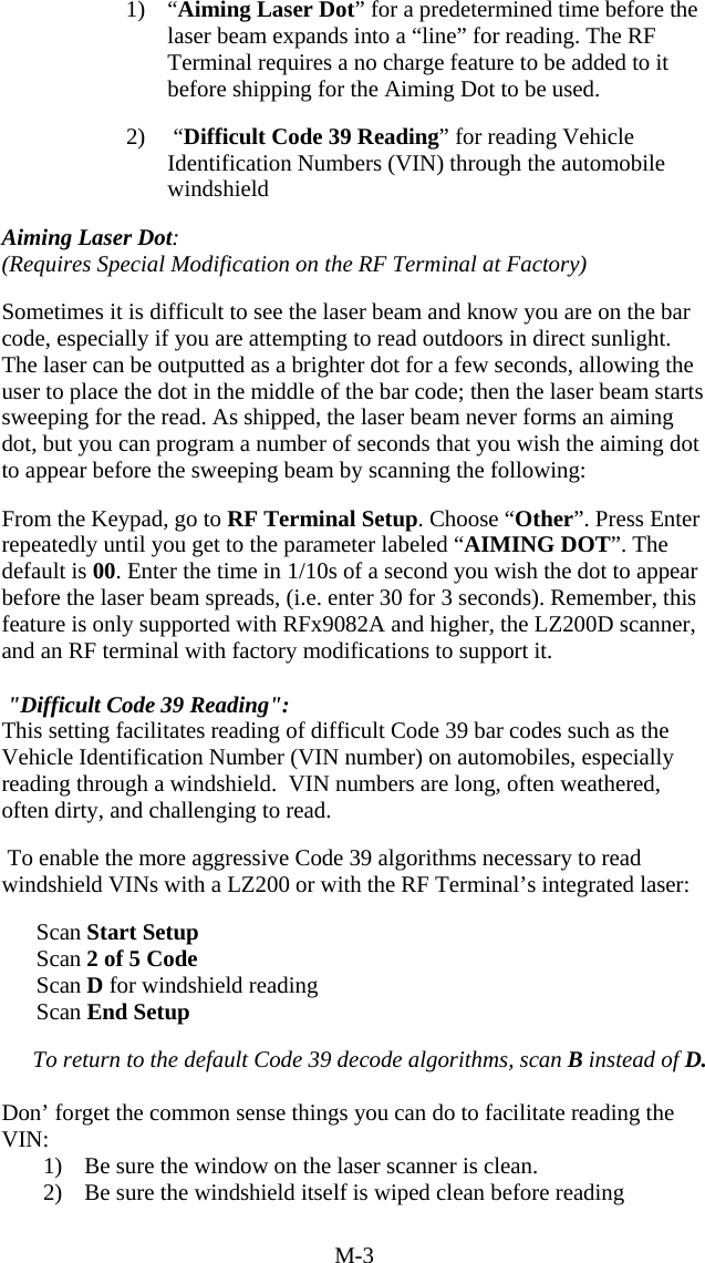
![2-28 Leave the cover off of the Base Station and plug in the power supply. You are ready to configure the Base Station using a RF Terminal. Base Station Setup using the RF Terminal Using a RF Terminal that is on the same frequency as the Base, stand close to the Base Station and turn on the Terminal. The Base Station is setup via the Terminals' keypad by entering Setup Mode from the menu. Turn on the Terminal and press any key. Answer NO to all prompts until you see: SETUP MODE? KEY [YES/NO]?_ Press the YES key. At this point, the terminal will ask for a password: SETUP MODE PASSWORD?_ Enter WDTRI on the keypad. The next item allows you to choose which item to configure: R/F Terminal------->1 R/F Base Setup--->2 Voice Operations->3 Choose 2 for RF Base Setup. If the RF Terminal is communicating with the Base Station, you will see the first Setup Parameter, BAUD RATE displayed on the RF Terminal screen. If you are not communicating with the Base Station, you will see the following message: Transmission Failed. To Retry, Move Closer and Press Enter. F1 to Exit._ Move closer and retry by pressing the ENTER key. If you still fail, check that the Base Station is jumpered correctly, is powered up and is on the same frequency as your RF Terminal. If you still have problems, see the Troubleshooting section of this manual. If you have successful communication, proceed with your Setup. After changing each parameter, press the ENTER key to move on to the next parameter.](https://usermanual.wiki/Worthdata/LT701/User-Guide-377201-Page-41.png)
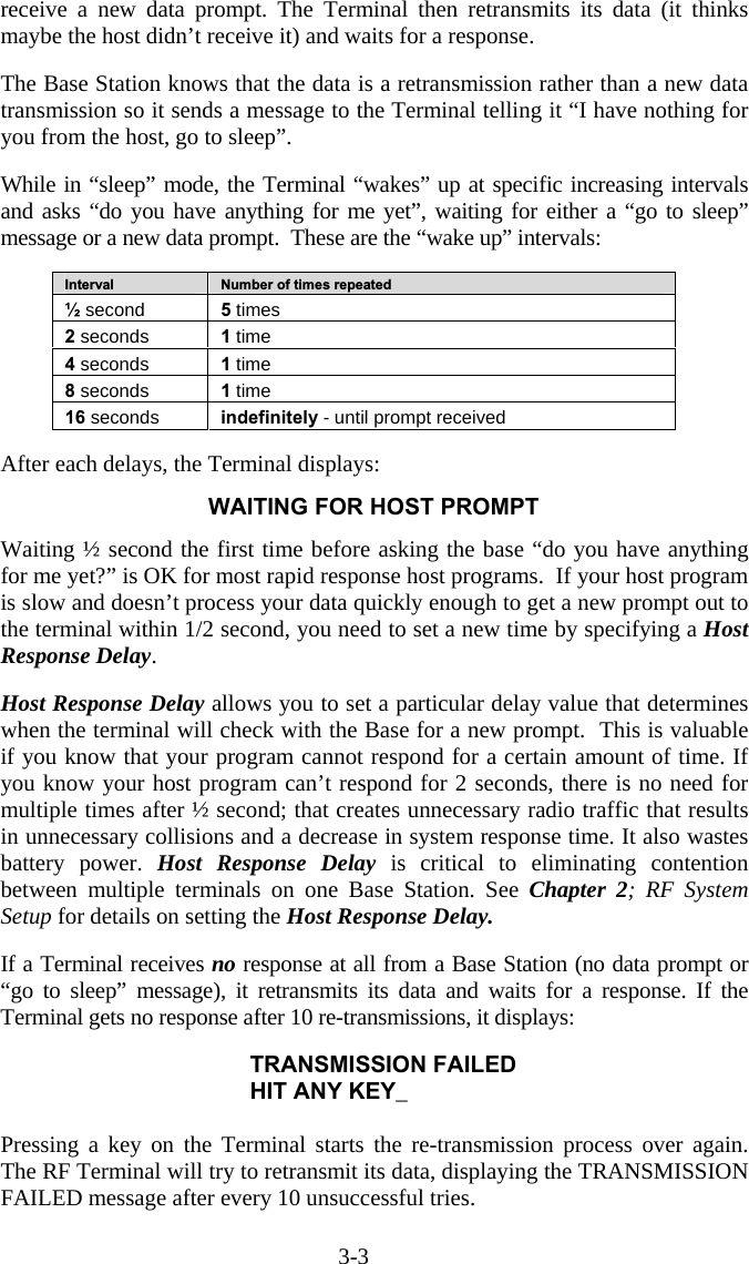
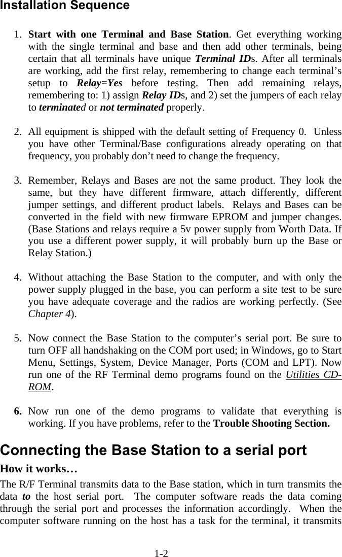
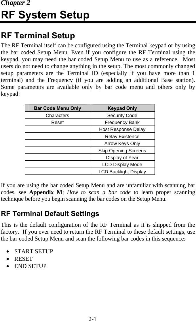
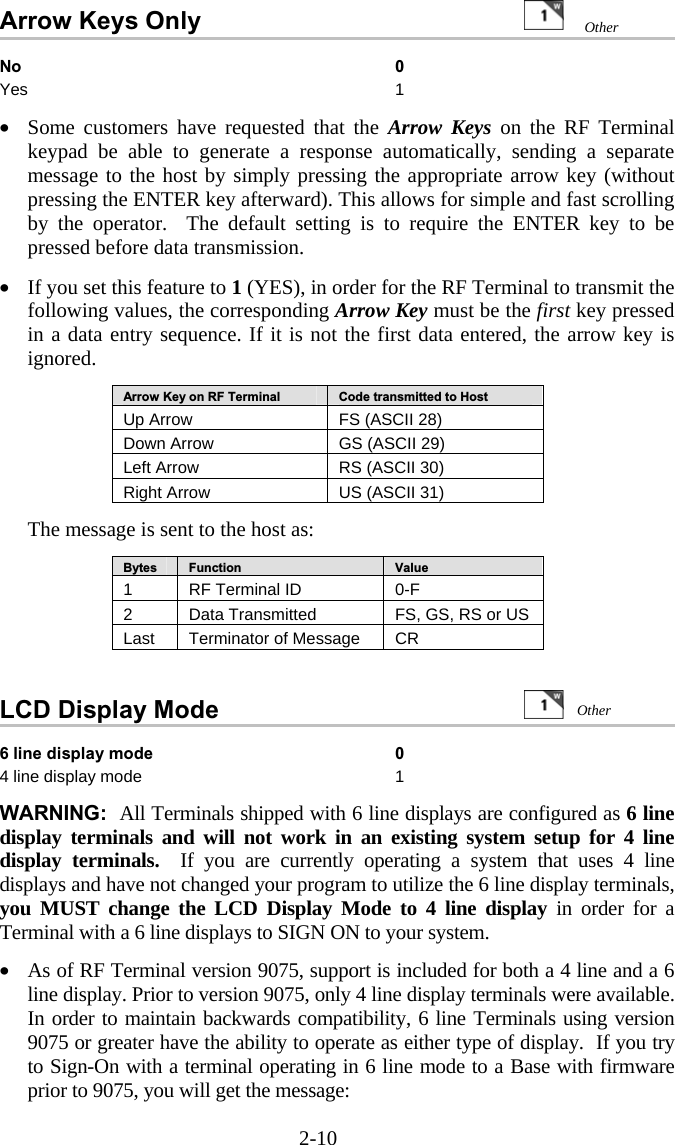
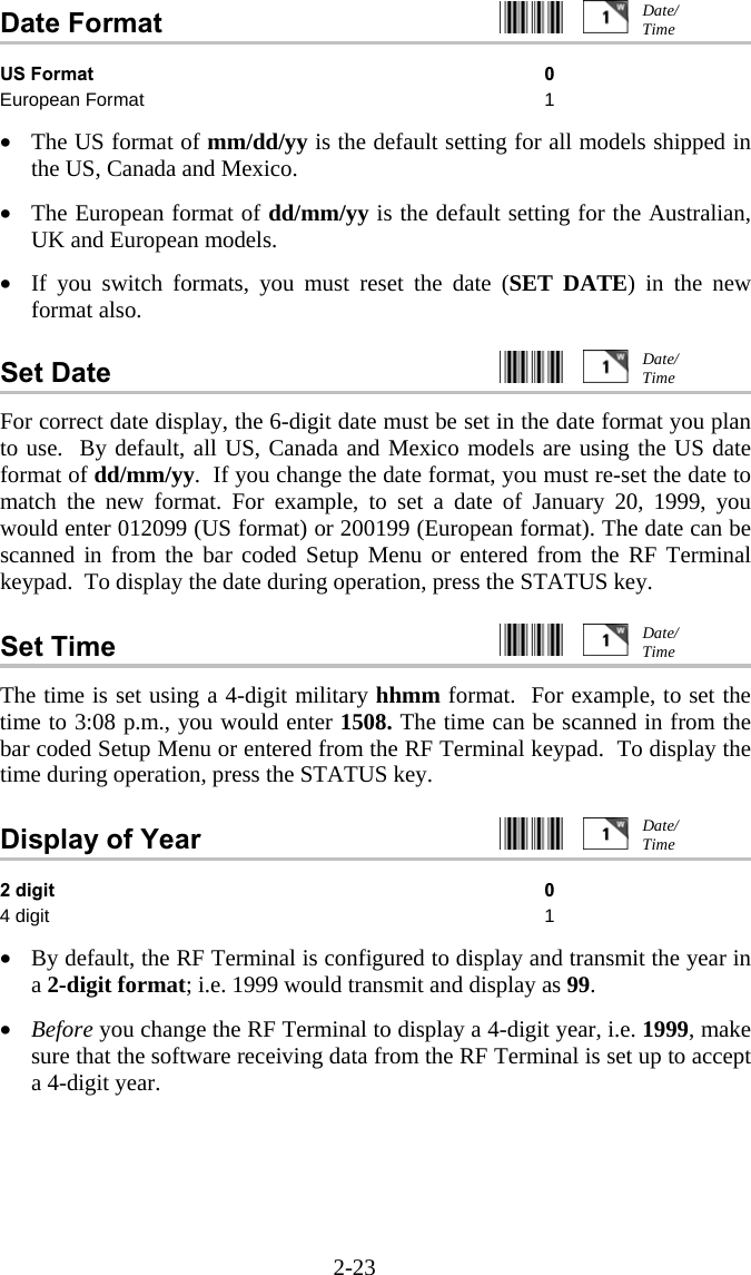
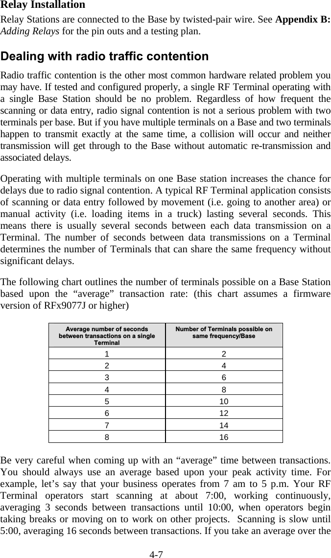
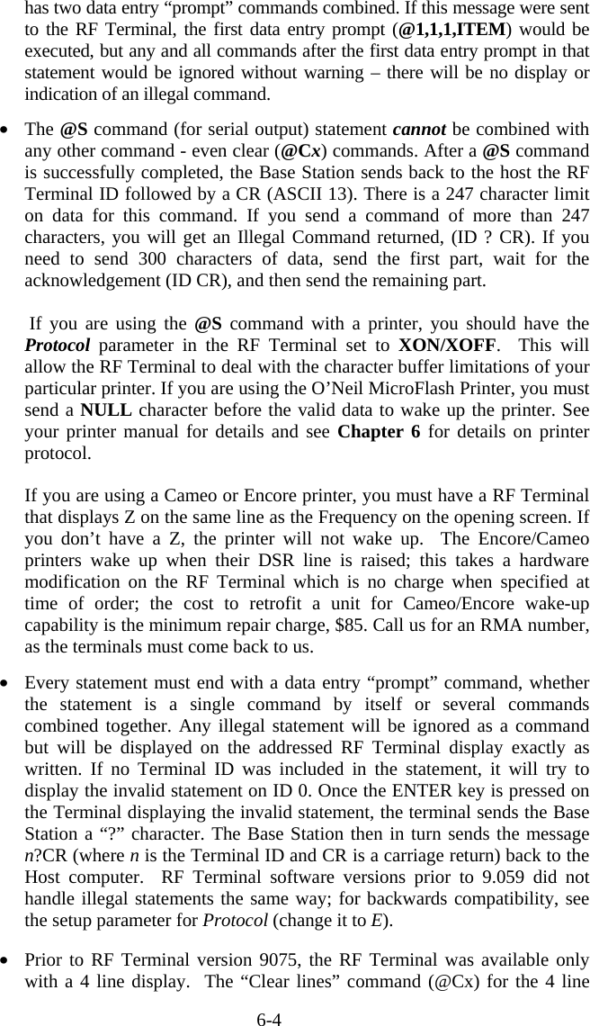
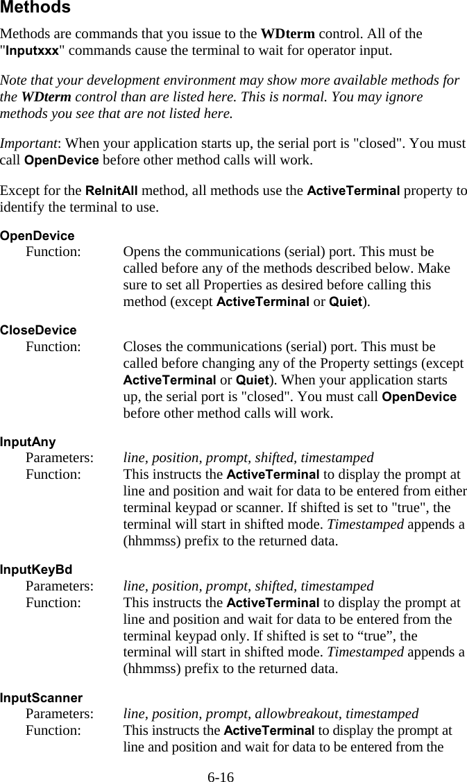
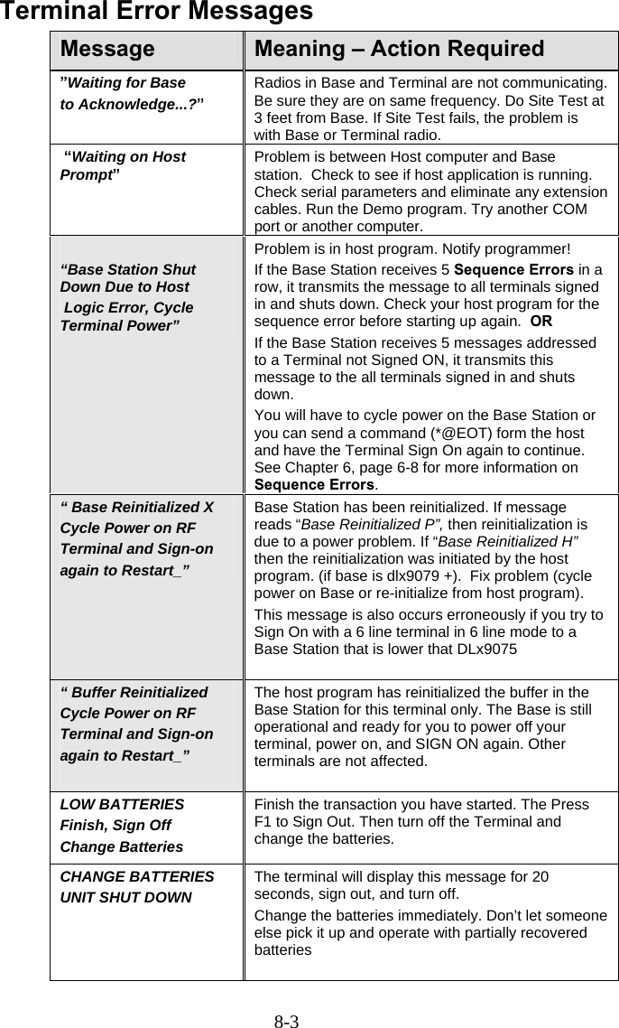
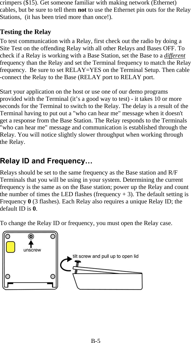
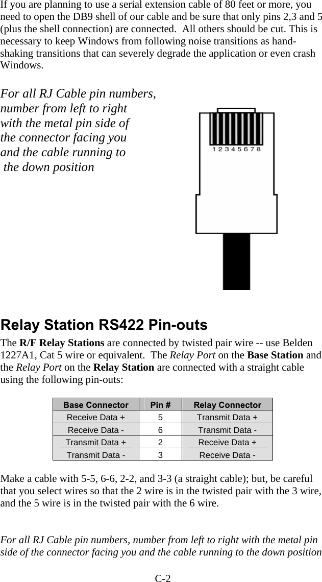
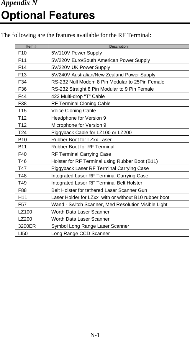
![3-4 How the One-Way RF System works The RF System can be used to perform “dumb” data entry to the computer – you could even use Portkey to transmit the data as though it has been entered from the keyboard. This is useful if you want to enter data directly into an application. This type of data transmission is called One-Way Mode. Once the RF Terminal transmits data to the Base Station, the Base Station acknowledges receipt of the information by echoing back the data to the Terminal that sent it, along with a beep. If the data transmission did not make it through to the Base station after 10 tries, the RF Terminal will give two long beeps and display the following message: TRANSMISSION FAILED TO RETRY, MOVE CLOSER AND PRESS ENTER. F1 TO EXIT. One-Way mode also works well as a “demo” program since it doesn’t require a program running on the host computer or even that the Base Station be connected to the host. If you want data to display on the host computer, simply run a program such as Windows’ Terminal (be sure to disable Xon/Xoff) or our Portkey program (for keyboard emulation). To get into One-Way Mode: At power up, the RF Terminal asks if you want to SIGN ON? KEY [YES/NO]?_ SIGN ON is for Two-Way communication only. Press NO, then press NO again at: SETUP MODE? KEY [YES/NO]?_ When you see: ONE WAY MODE? KEY [YES/NO]?_ Press YES. If the Base Station already has other RF Terminals signed on in Two-Way mode, you will not be allowed into the system. A Base Station must be dedicated to one mode at a time. If the Base Station is dedicated to One-Way mode, you will see the following prompt on the RF Terminal display: Data Received Was Enter Data? Since you have just started your One-Way session, there is no data to display on line #2. Line #3 is now asking you to scan or key data into the RF Terminal. If](https://usermanual.wiki/Worthdata/LT701/User-Guide-377201-Page-50.png)
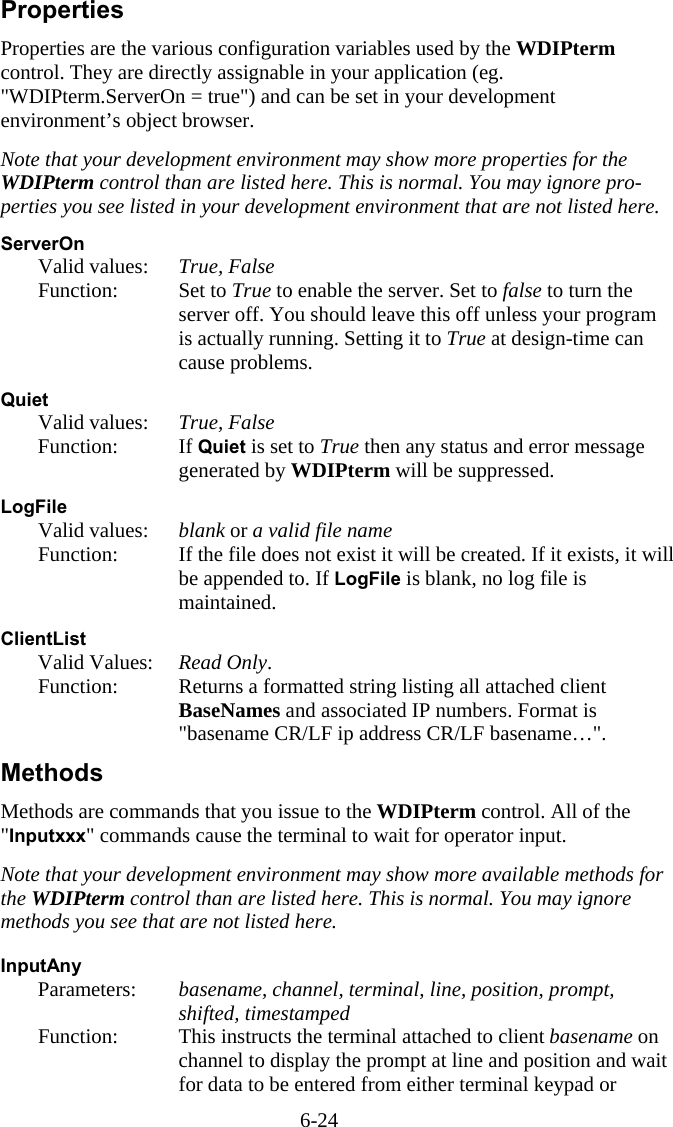
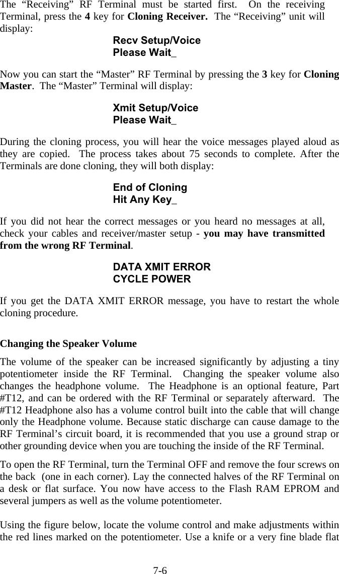
![7-3 Programming Voice Messages To record and playback messages or assign messages to error conditions, you have to get to SETUP MODE and enter the password. If you don’t know how to do this, see Chapter 2; RF System Setup for details on how to get into the SETUP MODE. Once you have entered the password (OK, its WDTRI) you will see the following prompt: R/F Terminal Setup->1 R/F Base Setup------>2 Voice Operations---->3 Press 3 to select Voice Operations. The next screen gives you your options: Record/Playback--->1 Assign Errors------->2 Cloning Master----->3 Cloning Receiver-->4 Pressing the “1” key takes you into the voice recording and playback function. Pressing the “2” key allows you to assign voice message numbers to error conditions. “3” and “4” allow you to clone voice messages from one RF Terminal to another. Each option is shown in detail below: Recording and Playback of Voice Messages If you respond with a “1” at the menu, you will see the following Record/Playback prompt: RECORD/PLAYBACK? KEY [R/P]? First, we will playback a message that has already been recorded. Let’s use message #01 for this example. Press the P key (for Playback) to get to the next prompt: KEY [R/P]? MESSAGE #: _ At this prompt, enter a two digit number for the message number you want to listen to. Enter “01” and then press the ENTER key. You will probably hear the “ITEM” prompt recorded at the factory unless you have edited or reset the default messages. If you heard nothing, a new message can be safely recorded in the area assigned to message # 01. After you have heard the message (or static if no message has been recorded), the RF Terminal displays the RECORD/PLAYBACK prompt again: RECORD/PLAYBACK? KEY [R/P]?](https://usermanual.wiki/Worthdata/LT701/User-Guide-377201-Page-99.png)
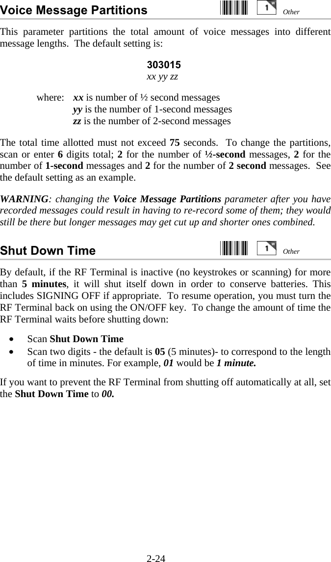
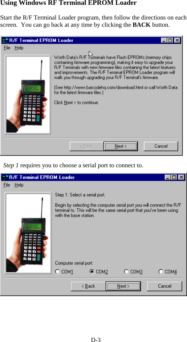
![7-4 To record a message, get out the microphone (no, it’s not an earphone) shipped with the RF Terminal and plug it into the AUX jack located next to the POWER jack on the bottom of the RF Terminal. Answer the prompt by pressing the R key to record a message. The bottom line of the display now reads: MESSAGE #: _ Enter the message number you are going to record. For this example, enter message #03 (by default this is a blank message) by pressing 03, then the ENTER key. The RF Terminal screen now shows: HIT ANY KEY TO START RECORDING To record a message, press any key and hold it down. When you release the key, immediately start speaking into the microphone. To practice, let’s record something in message #03. Get ready to say ITEM (in English or your language) into the microphone of the RF Terminal. When ready, press the ENTER key and the instant you release it, speak ITEM into the microphone. Remember to speak clearly – you have plenty of time to say ITEM in ½ second. When the message time is over, you will hear two beeps. The display is back to the RECORD/PLAYBACK prompt: RECORD/PLAYBACK? KEY [R/P]? Now you’re ready to listen to your first recording. Press the P key and key in 03 for the message number. Do not be discouraged if you didn’t record the entire message. Our first attempt produced “EM” in a very frantic tone of voice. Practice speaking clearly and calmly (think of the poor guy who has to hear it 10,000 times next week) as soon as the key is released. You will get the hang of it with just a little practice. That is the way all messages – prompts and errors - are recorded. If you are not sure which message numbers are blank, you can listen to messages until you find a blank for recording. The host computer relies on the fact that the voice messages are stored in the RF Terminal itself and not generated by the host. The host computer will trigger the broadcast of a voice message by sending a prompt to the RF Terminal that tells it which message number to play. If the host thinks that message #05 is STOP when it’s really GO, it can cause confusion for the operator. That is why it is important to keep track of what messages are recorded where.](https://usermanual.wiki/Worthdata/LT701/User-Guide-377201-Page-100.png)
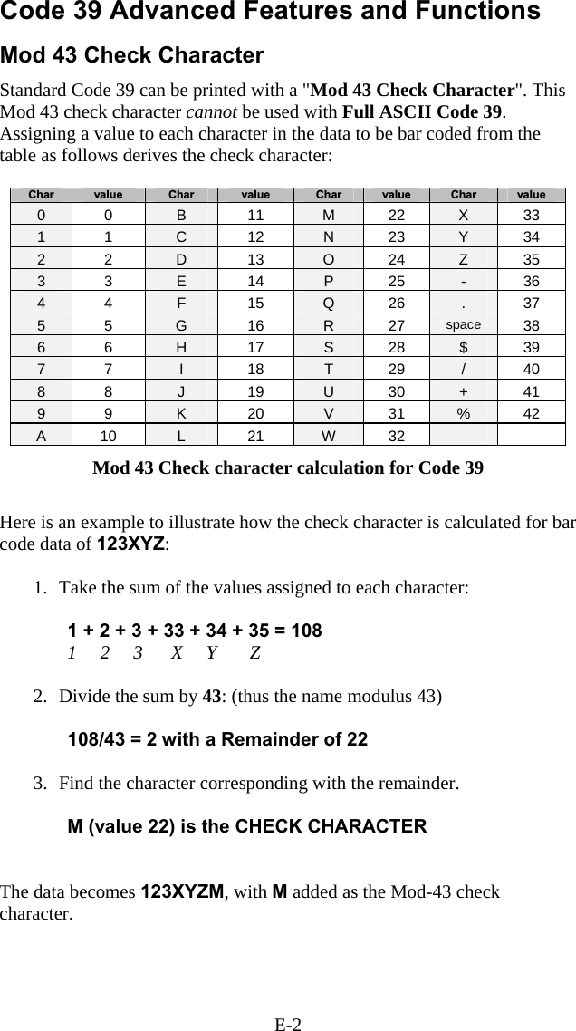
![E-3 Full ASCII Extension to Code 39 "Full-ASCII Code 39" expands the Code 39 character set to include all 128 ASCII characters. Symbols 0-9, A-Z and punctuation characters and are identical to their Code 39 representations. Lower-case letters, additional punctuation characters, and control characters are represented by sequences of two Code 39 characters. This table depicts the Full ASCII character set as a function of Code 39 characters: ASCII Code 39 ASCII Code 39 ASCII Code 39 ASCII Code 39 NUL %U SP Space @ %V ‘ %W SOH $A ! /A A A a +A STX $B “ /B B B b +B ETX $C # /C C C c +C EOT $D $ /D D D d +D ENQ $E % /E E E e +E ACK $F & /F F F f +F BEL $G ‘ /G G G g +G BS $H ( /H H H h +H HT $I ) /I I I i +I LF $J * /J J J j +J VT $K + /K K K k +K FF $L , /L L L l +L CR* $M - - or /M M M m +M SO $N . . or /N N N n +N SI $O / /O O O o +O DLE $P 0 0 or /P P P p +P DC1 $Q 1 1 or /Q Q Q q +Q DC2 $R 2 2 or /R R R r +R DC3 $S 3 3 or /S S S s +S DC4 $T 4 4 or /T T T t +T NAK $U 5 5 or /U U U u +U SYN $V 6 6 or /V V V v +V ETB $W 7 7 or /W W W w +W CAN $X 8 8 or /X X X x +X EM $Y 9 9 or /Y Y Y y +Y SUB $Z : /Z Z Z z +Z ESC %A ; %F [ %K { %P FS %B < %G \ %L | %Q GS %C = %H ] %M } %R RS %D > %I ^ %N ~ %S US %E ? %J _ %O DEL %T, %X Full ASCII Table](https://usermanual.wiki/Worthdata/LT701/User-Guide-377201-Page-139.png)
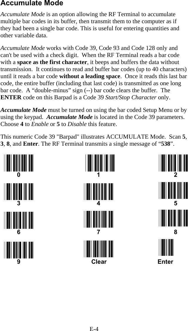
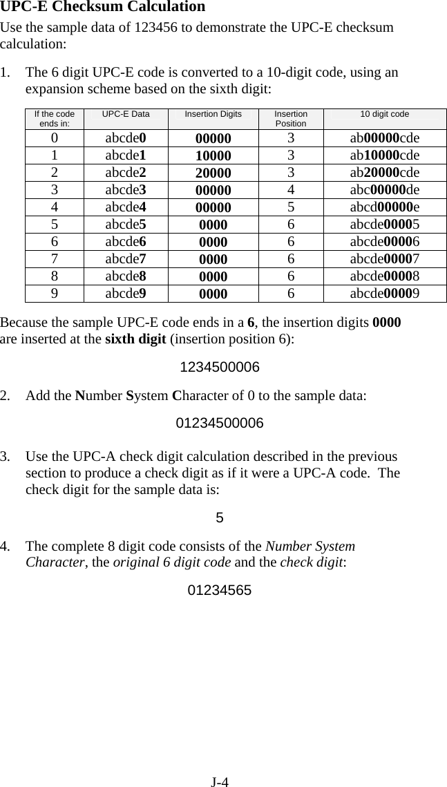
![H-1 Appendix H Code 128 Specifications Code 128 is a very powerful bar code, combining an extensive character set and variable length with compactness and error checking. The character set contains all 128 ASCII characters with each character made up of three bars and three spaces. Each element (bar or space) varies from one to four units in width, totaling 11 units of width per character. Code 128 contains two levels of error checking: • Each character is checked for internal parity, and • The last character is a checksum. Code 128 has three subsets, A, B and C. Subset A contains alphanumeric characters and unprintable control characters, subset B contains alphanumeric characters plus printable control characters and subset C contains only numeric characters and uses a 2-character encoding scheme to create a more compact bar code. Code 128 uses an internal Mod 103 check character that is not displayed by the bar code reader. Code 128 bar codes can be made up of only one subset or may be a combination of several. The Code 39 features of Accumulate Mode, Caps Lock ON and Caps lock OFF also apply to Code 128. UCC-128/ EAN-128 UCC-128/EAN-128 Code is a subset of Code 128 adopted by the UCC and EAN council’s for use as a shipping label symbology. UCC/EAN-128 bar codes always start with a Function Code 1 character. In addition, a Function Code 1 character terminates all variable length fields unless they are the last field in the bar code. The RF Terminal outputs the following for the special function codes and start sequences: ]C1 Start C/Function Code 1 ^] (GS) Function Code 1 as a variable string terminator If UCC/EAN 128 is enabled, the reader looks for the Start C/Function Code 1 to indicate a UCC/EAN 128 bar code. 12345](https://usermanual.wiki/Worthdata/LT701/User-Guide-377201-Page-145.png)
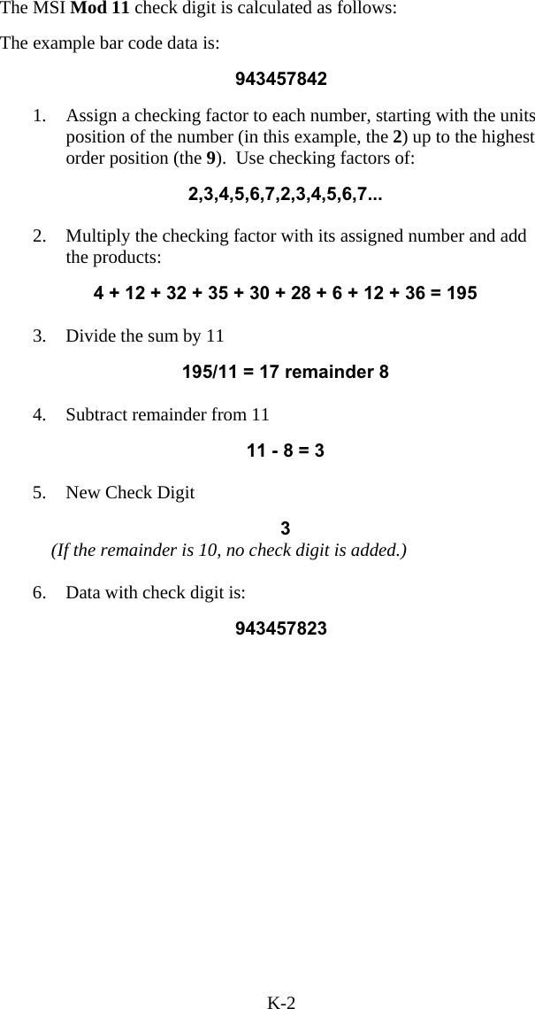
![H-2 The UCC Serial Shipping Container Code specification calls for a 19 digit UCC/EAN 128 code with an additional Mod 10 Check digit (20 digits in all). The Mod 10 Check digit is calculated the same as the Interleaved 2 of 5 example in Appendix D. It is the data length as well as the MOD 10 check digit that distinguishes the UCC Serial Shipping Container Code from other UCC /EAN 128 bar codes. Scanning the appropriate bar codes on the RF Terminal Setup Menu enables UCC/EAN 128; or you can use the keypad in the PROGRAMMING MODE “Change Setup” option. If UCC/EAN 128 is enabled, you will be able to read both standard Code 128 bar codes as well as the UCC/EAN 128 bar codes with the Function 1 character and the Mod 10 check character. UCC-128 Shipping Container Code If UCC/EAN-128 is enabled on the R/F Terminal reader, all Function 1 codes are transmitted as ]C1. In addition, should you be reading a 20 digit Shipping Serial Container code, the Mod 10 check digit is also compared with the computed Mod 10 value to give further assurance of no substitutions. The UCC/EAN-128 Shipping Serial Container Code is a subset of UCC-128 or EAN-128 adopted for voluntary marking of shipping boxes with the exact serial number of the box, (used with EDI typically to identify a specific boxes contents. The code consists of the following format: Start C not transmitted Function Code 1 transmitted 2 Digit Qualifier transmitted 7 Digit Data Portion transmitted 1 Digit Mod 10 Check Digit* transmitted- 1 Digit Modulus 103 not transmitted Stop Code not transmitted *Calculated using 19digits-UPC method The UCC 128 specification is used extensively by the retail industry. If you have a requirement for a UCC 128 Serial Shipping Container bar code, be sure to follow the specification as closely as possible as many vendors will](https://usermanual.wiki/Worthdata/LT701/User-Guide-377201-Page-146.png)


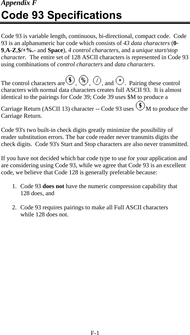
![O-1 Appendix O ASCII Code Equivalent Table The 128 ASCII codes, their 3-digit decimal equivalents and 2-digit hex equivalents are detailed in the below table. char hex 3 digit ASCII char hex 3 digit ASCII char hex 3 digit ASCII char hex 3 digit ASCII NUL 00 000 SP 20 032 @ 40 064 ‘ 60 096 SOH 01 001 ! 21 033 A 41 065 a 61 097 STX 02 002 " 22 034 B 42 066 b 62 098 ETX 03 003 # 23 035 C 43 067 c 63 099 EOT 04 004 $ 24 036 D 44 068 d 64 100 ENQ 05 005 % 25 037 E 45 069 e 65 101 ACK 06 006 & 26 038 F 46 070 f 66 102 BEL 07 007 ' 27 039 G 47 071 g 67 103 BS 08 008 ( 28 040 H 48 072 h 68 104 HT 09 009 ) 29 041 I 49 073 i 69 105 LF 0A 010 * 2A 042 J 4A 074 j 6A 106 VT 0B 011 + 2B 043 K 4B 075 k 6B 107 FF 0C 012 , 2C 044 L 4C 076 l 6C 108 CR 0D 013 - 2D 045 M 4D 077 m 6D 109 SO 0E 014 . 2E 046 N 4E 078 n 6E 110 SI 0F 015 / 2F 047 O 4F 079 o 6F 111 DLE 10 016 0 30 048 P 50 080 p 70 112 DC1 11 017 1 31 049 Q 51 081 q 71 113 DC2 12 018 2 32 050 R 52 082 r 72 114 DC3 13 019 3 33 051 S 53 083 s 73 115 DC4 14 020 4 34 052 T 54 084 t 74 116 NAK 15 021 5 35 053 U 55 085 u 75 117 SYN 16 022 6 36 054 V 56 086 v 76 118 ETB 17 023 7 37 055 W 57 087 w 77 119 CAN 18 024 8 38 056 X 58 088 x 78 120 EM 19 025 9 39 057 Y 59 089 y 79 121 SUB 1A 026 : 3A 058 Z 5A 090 z 7A 122 ESC 1B 027 ; 3B 059 [ 5B 091 { 7B 123 FS 1C 028 < 3C 060 \ 5C 092 | 7C 124 GS 1D 029 = 3D 061 ] 5D 093 } 7D 125 RS 1E 030 > 3E 062 ^ 5E 094 ~ 7E 126 US 1F 031 ? 3F 063 _ 5F 095 DEL 7F 127 Full ASCII Equivalent Table](https://usermanual.wiki/Worthdata/LT701/User-Guide-377201-Page-169.png)
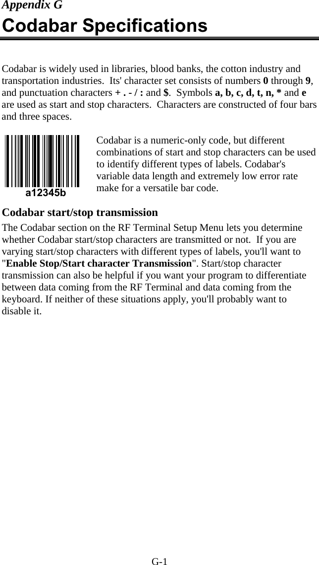
![P-1 Appendix P FCC Regulatory Statement This device is required to comply with FCC RF exposure requirements for mobile and fixed transmitting devices. The FCC requires that the antenna char hex 3 digit ASCII char hex 3 digit ASCII char hex 3 digit ASCII char hex 3 digit ASCII NUL 00 000 SP 20 032 @ 40 064 ‘ 60 096 SOH 01 001 ! 21 033 A 41 065 a 61 097 STX 02 002 " 22 034 B 42 066 b 62 098 ETX 03 003 # 23 035 C 43 067 c 63 099 EOT 04 004 $ 24 036 D 44 068 d 64 100 ENQ 05 005 % 25 037 E 45 069 e 65 101 ACK 06 006 & 26 038 F 46 070 f 66 102 BEL 07 007 ' 27 039 G 47 071 g 67 103 BS 08 008 ( 28 040 H 48 072 h 68 104 HT 09 009 ) 29 041 I 49 073 i 69 105 LF 0A 010 * 2A 042 J 4A 074 j 6A 106 VT 0B 011 + 2B 043 K 4B 075 k 6B 107 FF 0C 012 , 2C 044 L 4C 076 l 6C 108 CR 0D 013 - 2D 045 M 4D 077 m 6D 109 SO 0E 014 . 2E 046 N 4E 078 n 6E 110 SI 0F 015 / 2F 047 O 4F 079 o 6F 111 DLE 10 016 0 30 048 P 50 080 p 70 112 DC1 11 017 1 31 049 Q 51 081 q 71 113 DC2 12 018 2 32 050 R 52 082 r 72 114 DC3 13 019 3 33 051 S 53 083 s 73 115 DC4 14 020 4 34 052 T 54 084 t 74 116 NAK 15 021 5 35 053 U 55 085 u 75 117 SYN 16 022 6 36 054 V 56 086 v 76 118 ETB 17 023 7 37 055 W 57 087 w 77 119 CAN 18 024 8 38 056 X 58 088 x 78 120 EM 19 025 9 39 057 Y 59 089 y 79 121 SUB 1A 026 : 3A 058 Z 5A 090 z 7A 122 ESC 1B 027 ; 3B 059 [ 5B 091 { 7B 123 FS 1C 028 < 3C 060 \ 5C 092 | 7C 124 GS 1D 029 = 3D 061 ] 5D 093 } 7D 125 RS 1E 030 > 3E 062 ^ 5E 094 ~ 7E 126 US 1F 031 ? 3F 063 _ 5F 095 DEL 7F 127 Full ASCII Equivalent Table used for this transmitter must be installed to provide a separation of at least 20 cm (8 inches) from all persons (not including hands, wrists, feet, and ankles) and must not be co-located or operating in conjunction with any other antenna or transmitter.This device complies with Part 15 of the FCC Rules. Operation is subject to the following two conditions: (1) this device may not cause harmful interference, and (2) this device must accept any interference received, including interference that may cause undesired operation.](https://usermanual.wiki/Worthdata/LT701/User-Guide-377201-Page-170.png)