Worthdata LT802 802.11b Wireless CF Module User Manual
Worthdata Inc 802.11b Wireless CF Module Users Manual
UserManual.wiki
>
Worthdata
>
LT802 User Manual
Users Manual
Navigation menu
Upload a User Manual
Namespaces
Wiki Guide
HTML
PDF
Info
Views
User Manual
Discussion / Help
Navigation
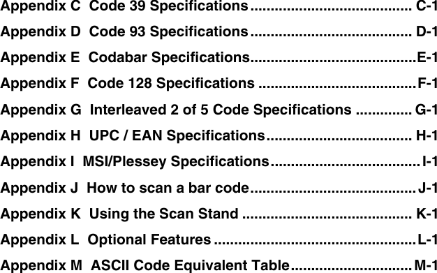
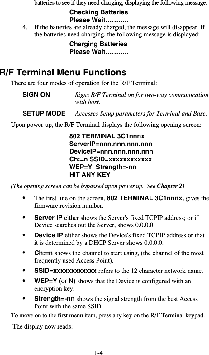
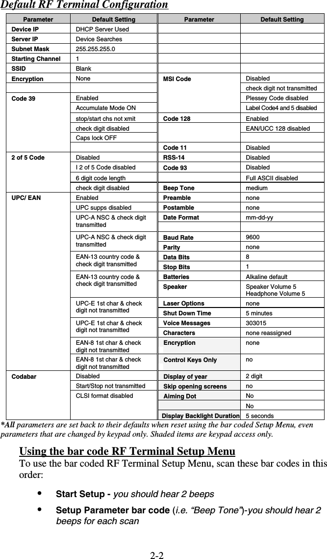
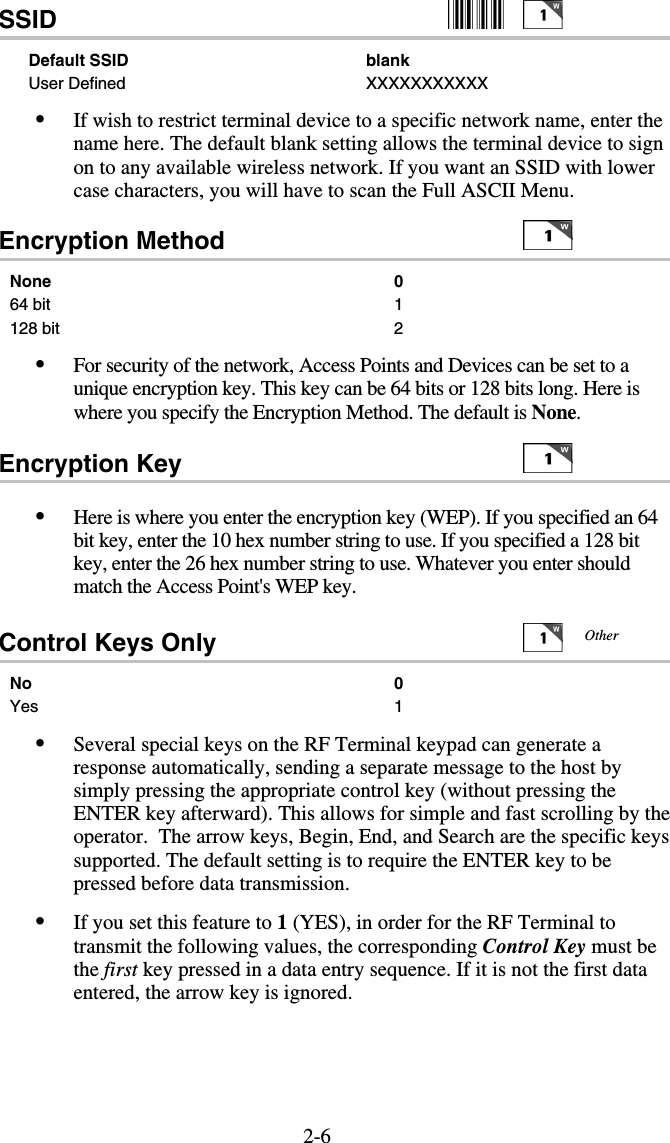
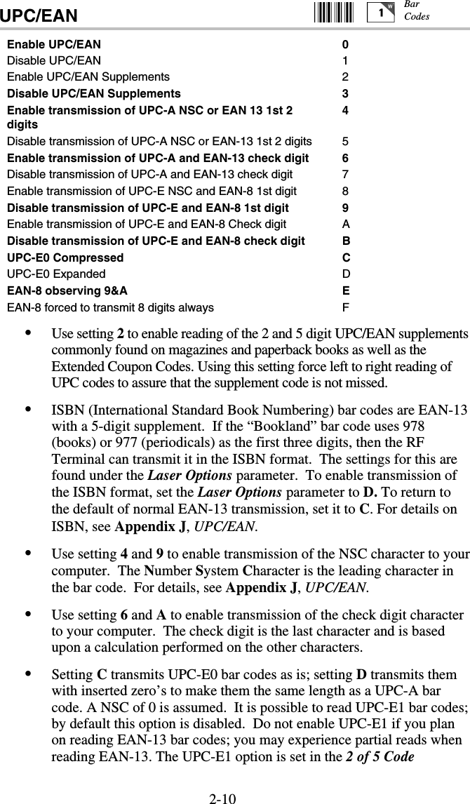
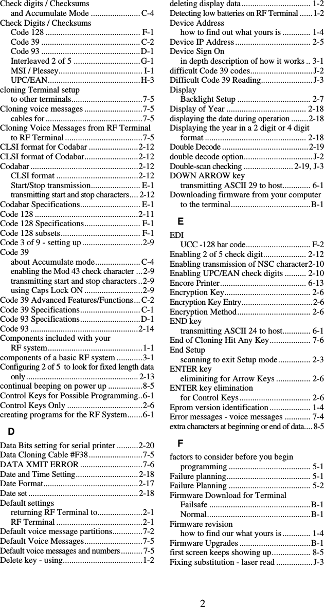
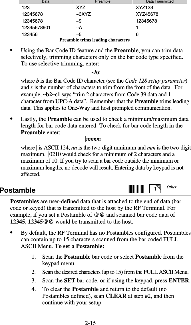
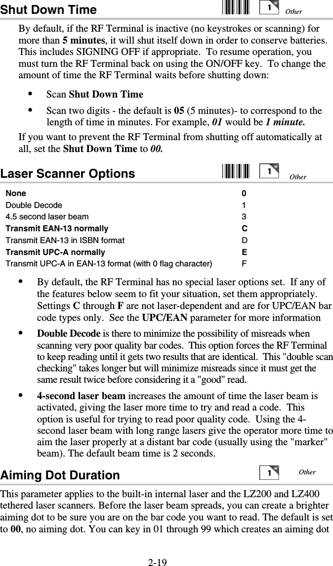
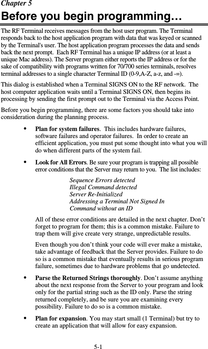
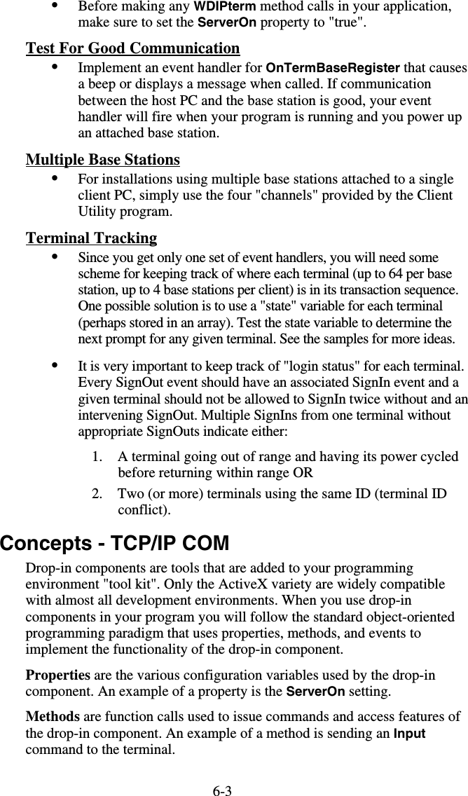
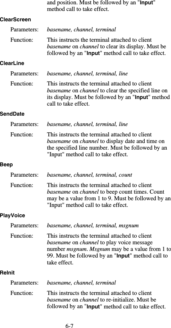
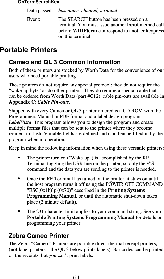
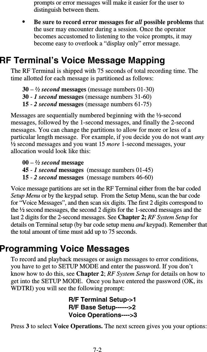
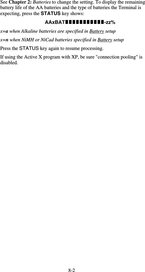
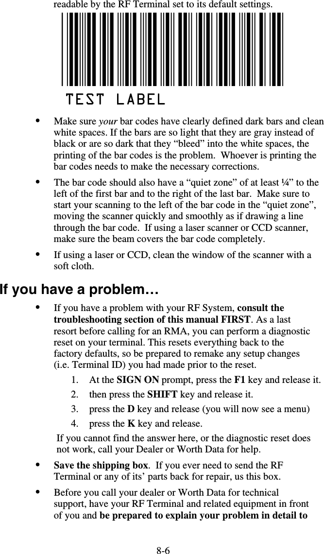
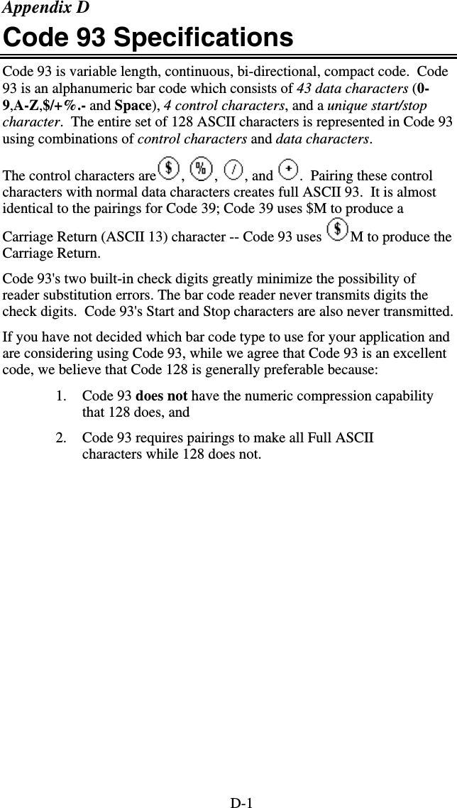
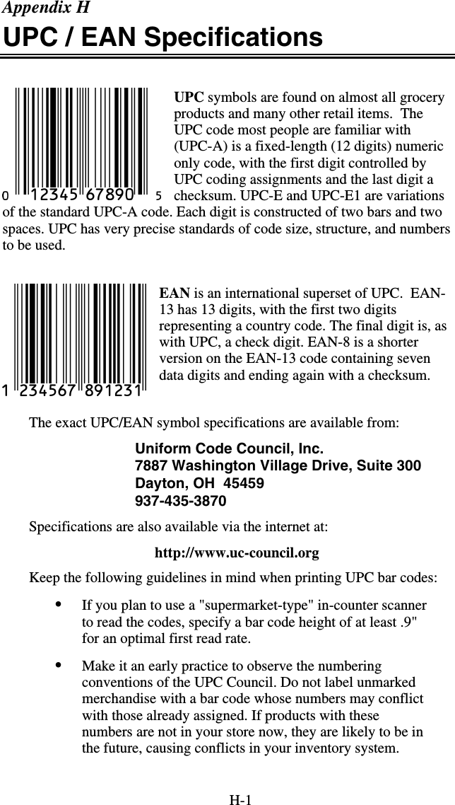
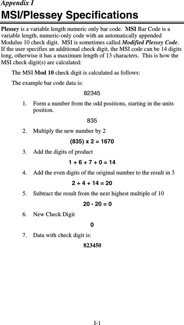
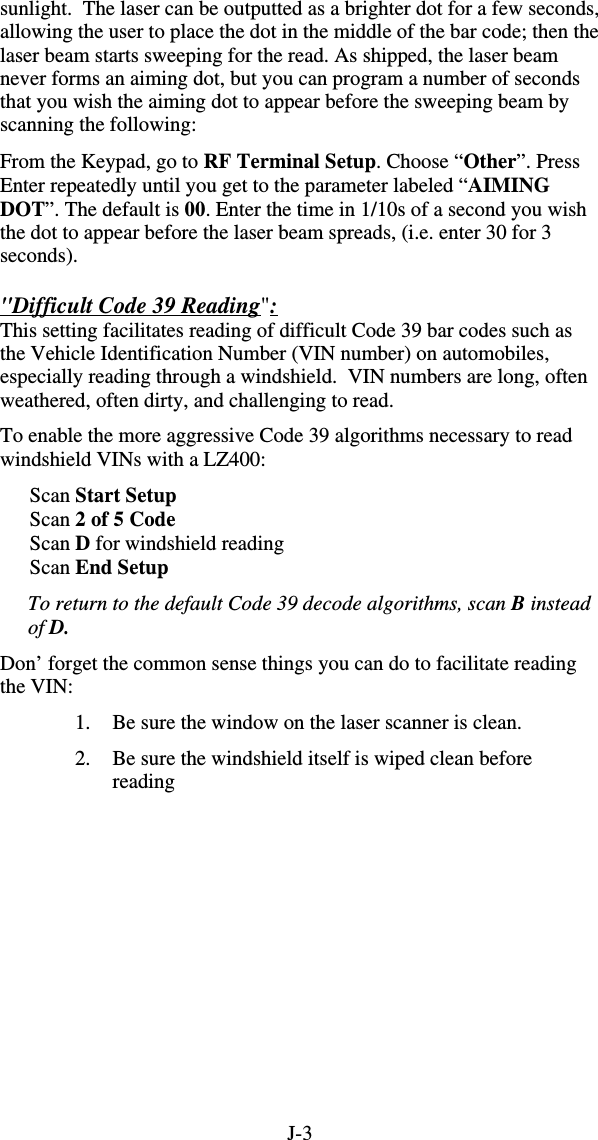
![2-132 of 5 Length Default setting 06 Valid entries 00-98 To read variable length 2 of 5 codes 00 • 2 of 5 is so susceptible to misreads that the RF Terminal adds an additional safeguard - it can be configured to look for fixed-length data only. • The default setting of 06 causes the RF Terminal to read only 2 of 5 codes that are 6 digits in length. To set the RF Terminal to read a different length, scan any two-digit number from the bar pad table. For example, to change the RF Terminal to accept an 8-digit bar code, scan 0 then 8 from the bar pad table. 2 of 5 code must always be an even number of digits so the length setting must always be an even number. • Reading variable length I 2of5 or 2 of 5 codes is to be avoided if at all possible. The 00 setting is supplied for the purposes of reading codes of unknown length, counting the digits and setting the length to the proper number. MSI and Plessey Disable MSI 0 Enable MSI, 1 Mod 10 check digit 1 Enable MSI, 2 Mod 10 check digits 2 Enable MSI, 1 Mod 11/ Mod 10 check digit 3 Transmit no check digits 4 Transmit 1 check digit 5 Transmit 2 check digits 6 Enable Plessey bar code (mutually exclusive with MSI) 7 Enable LabelCode5 (mutually exclusive w/MSI & Plessey) 8 Enable LabelCode4 (mutually exclusive w/all above) 9 • LabelCode5 and LabelCode4 are proprietary bar code types used by Follet. • If you have enabled the Mod 10 or Mod 11 check digits, they will be transmitted along with your bar code data from the RF Terminal to your host. • For more information regarding MSI or Plessey Code, see Appendix K; MSI Plessey Code. RSS-14 Disabled 0 14 digits with no identifiers, i.e. 10012345678902 1 14 digits + identifiers, i.e. ]e00110012345678902 2 14 digits + UCC-128 format, i.e. ]C110012345678902 3 Bar Codes Bar Codes](https://usermanual.wiki/Worthdata/LT802/User-Guide-599054-Page-23.png)
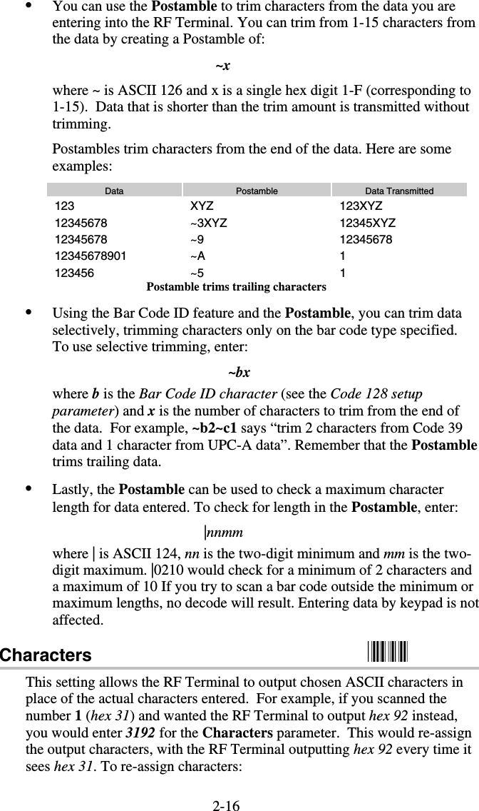
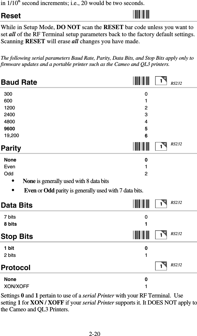

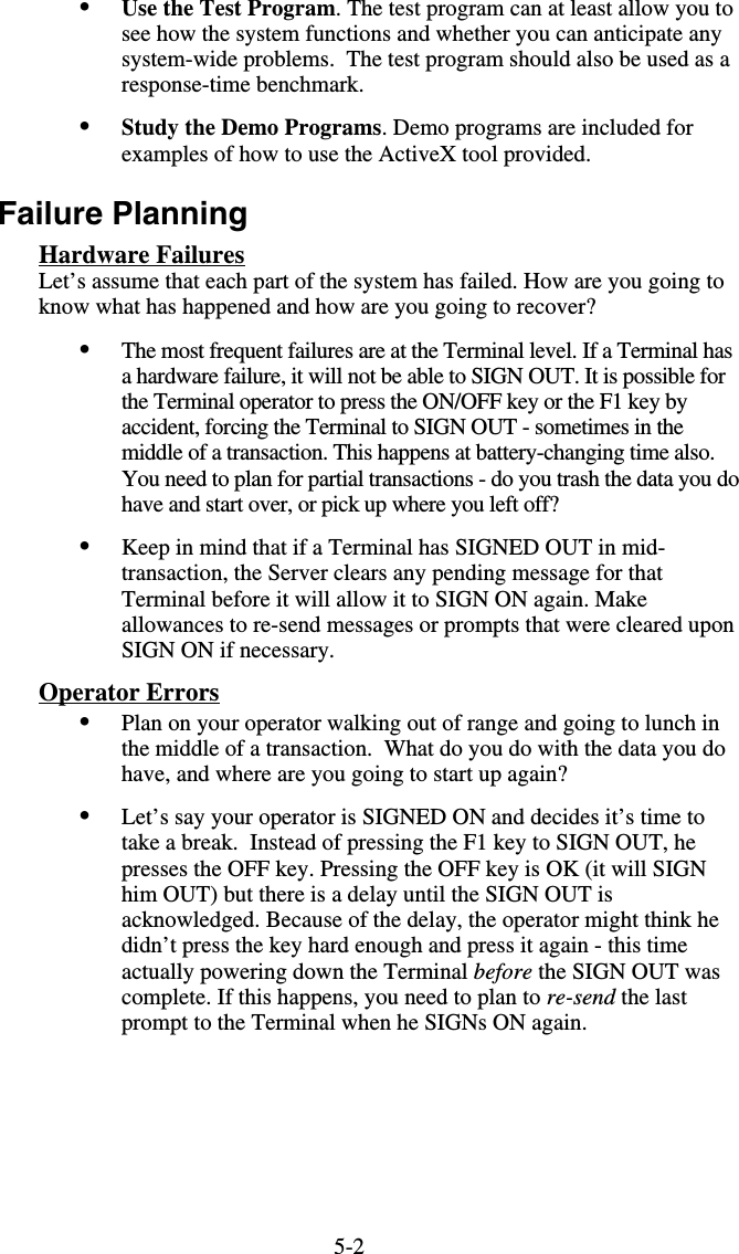
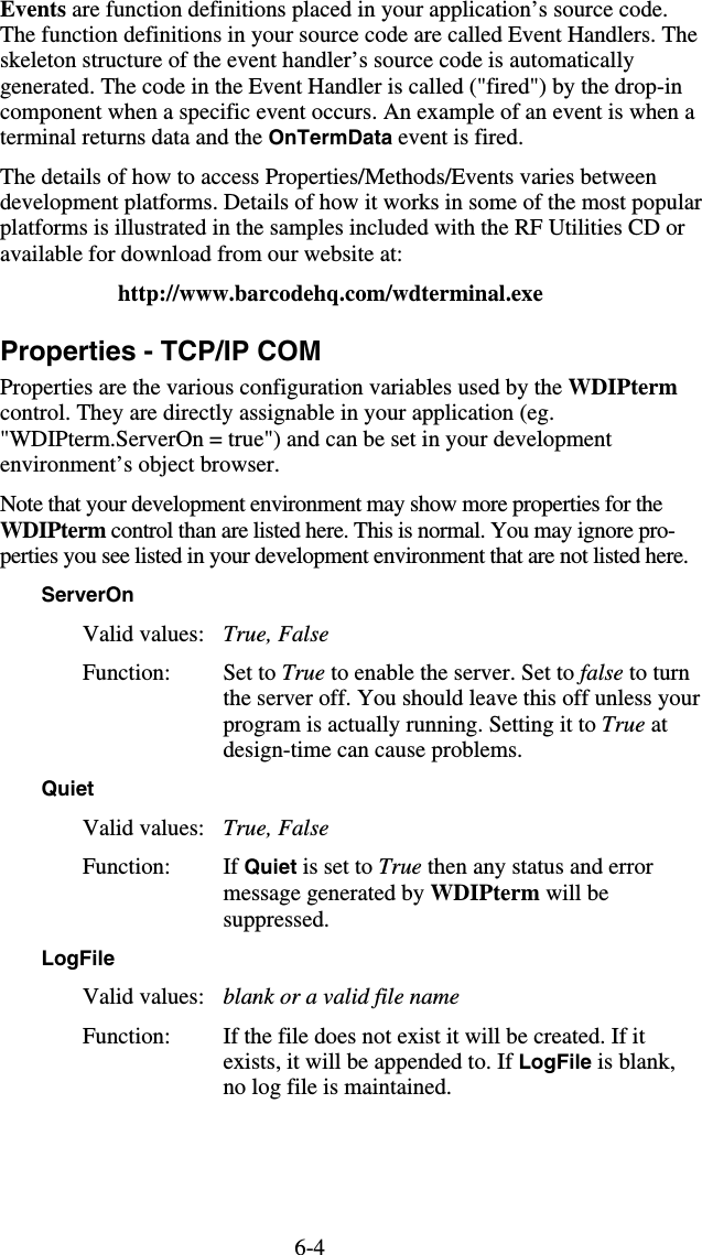
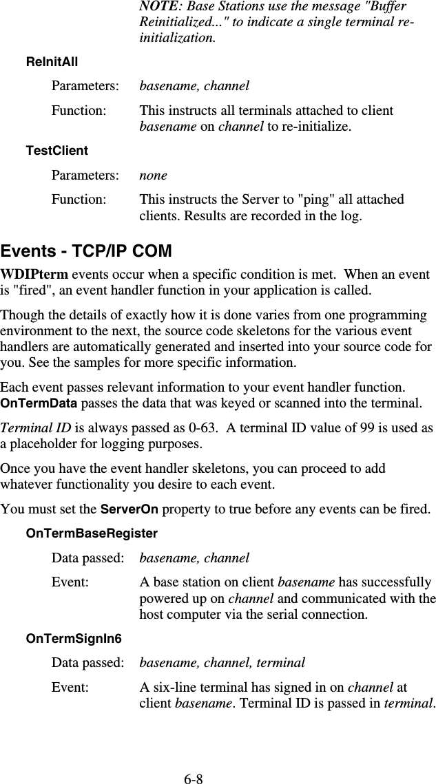
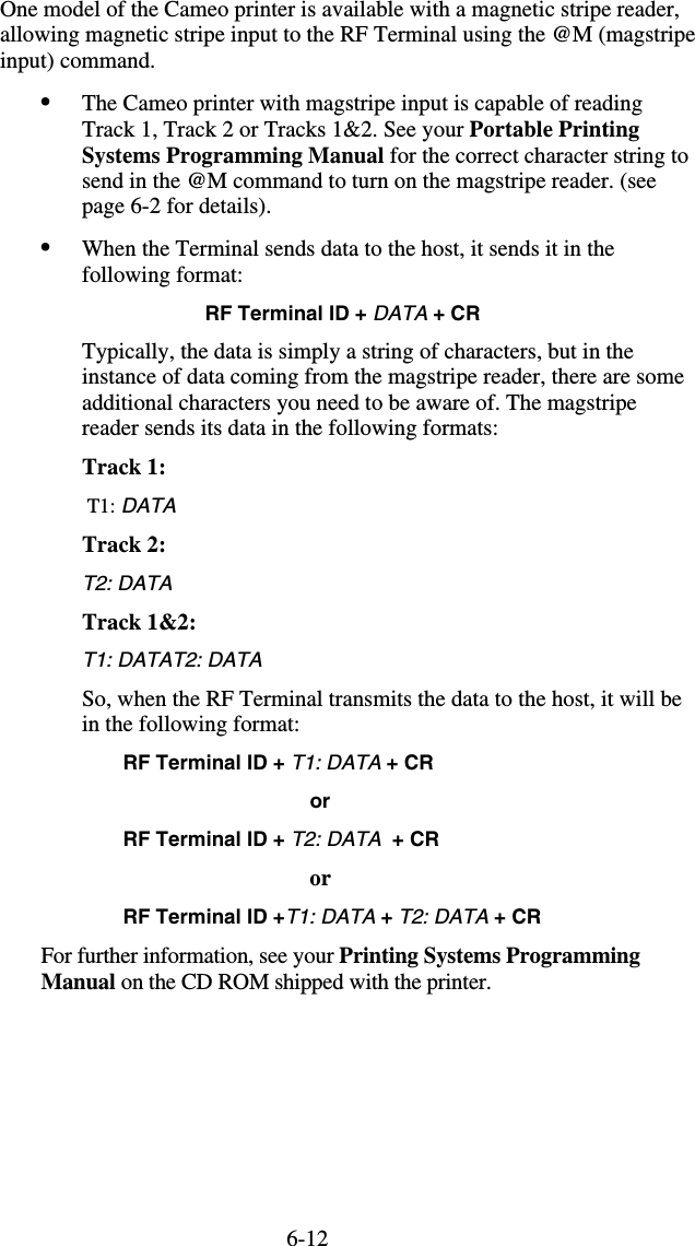
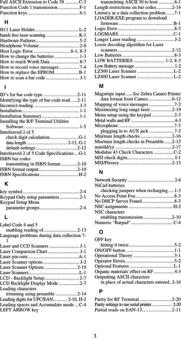
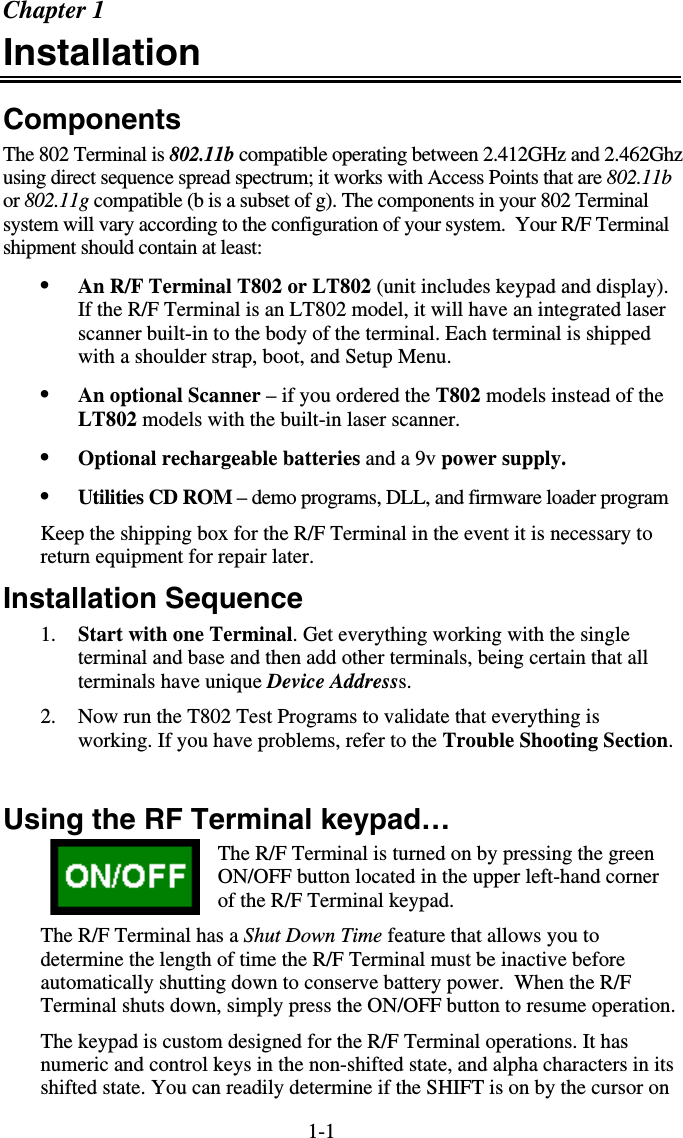
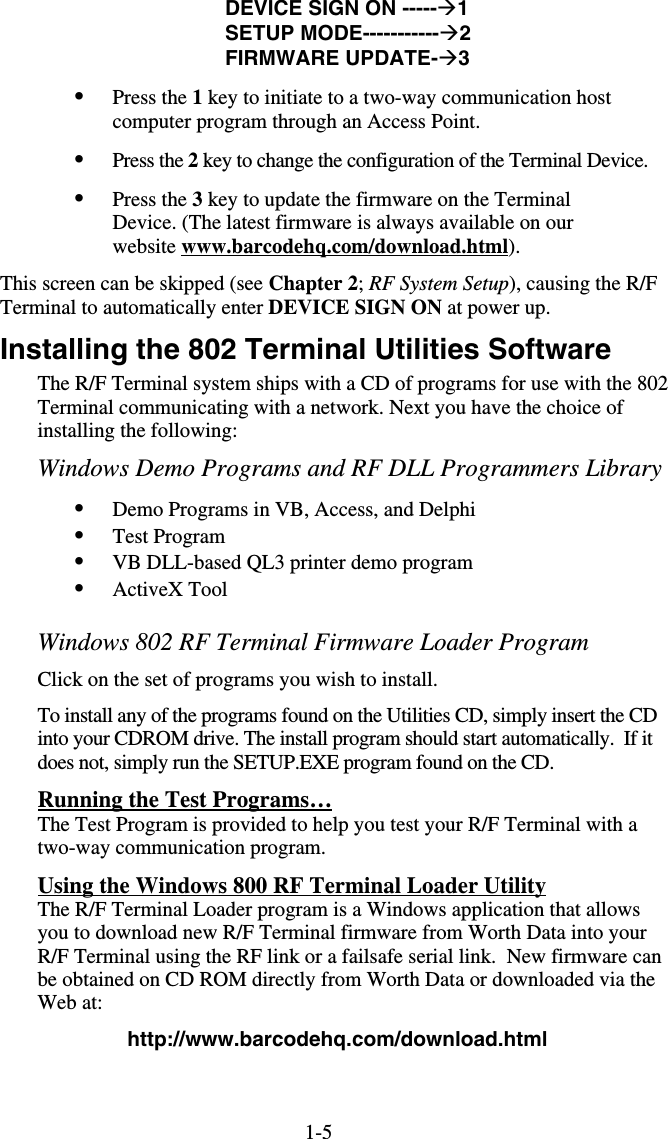
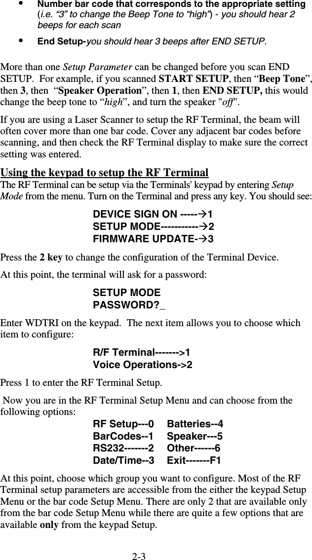
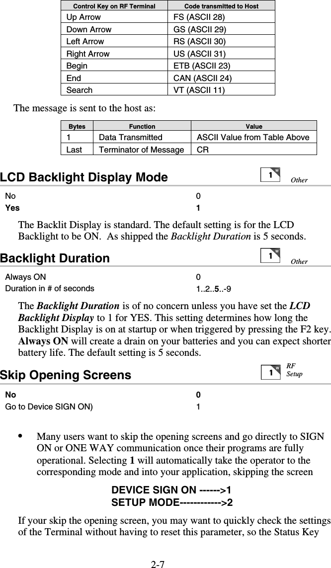
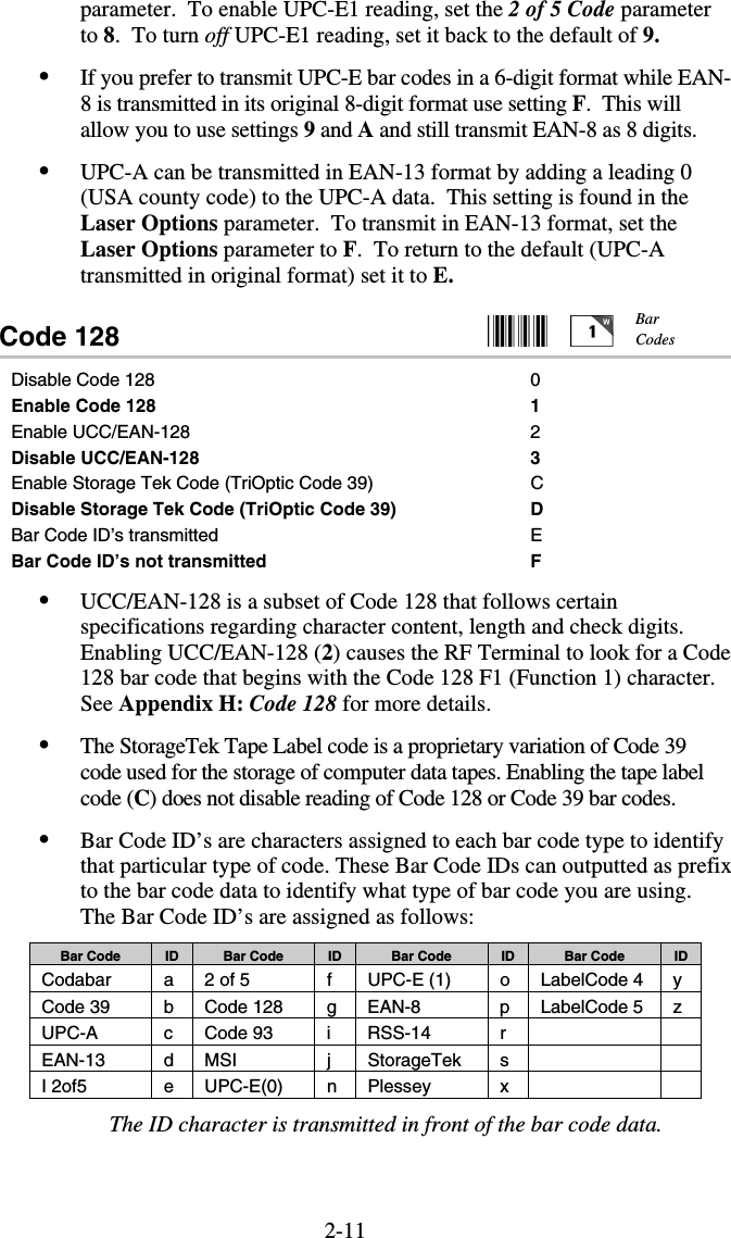
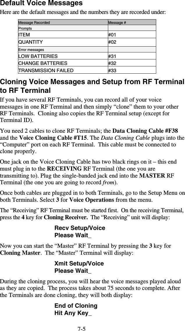
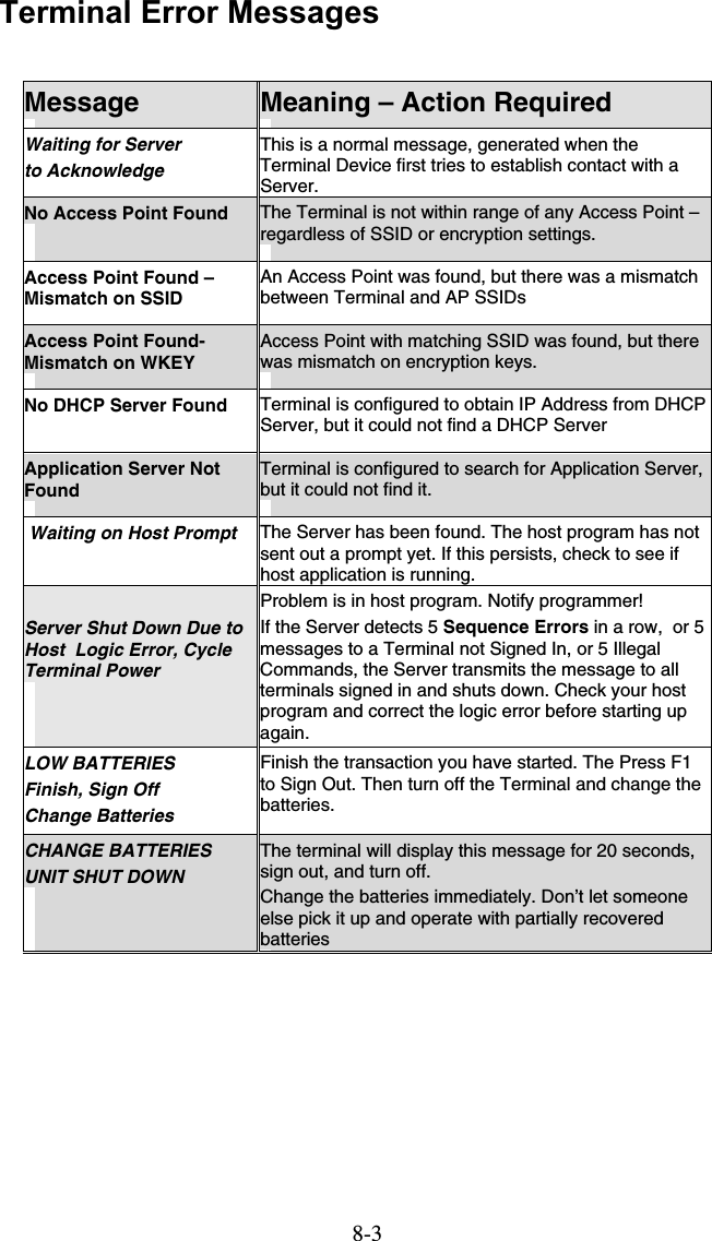
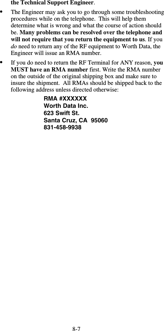
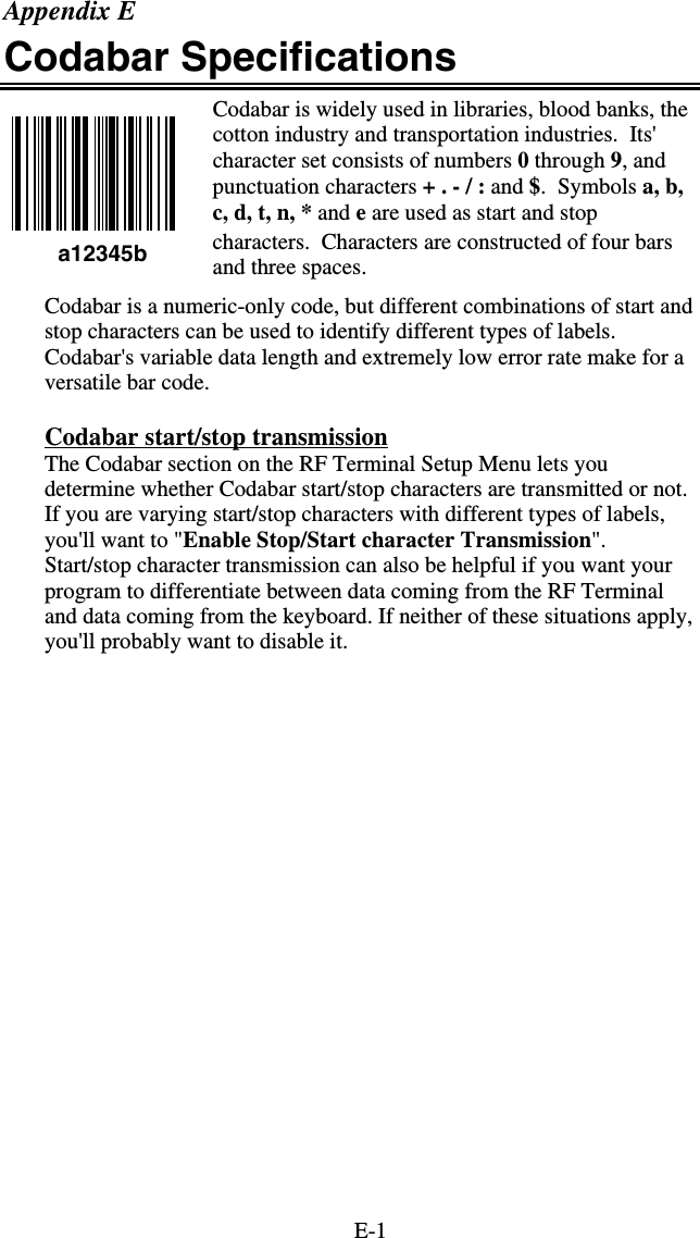
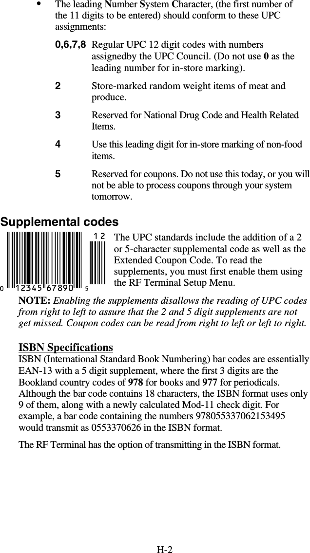
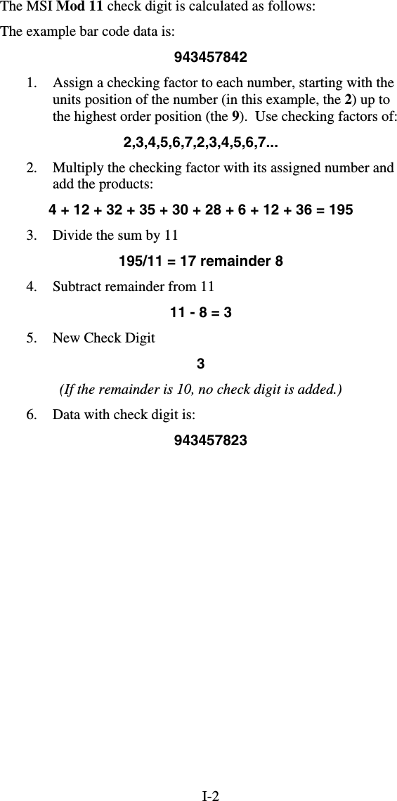
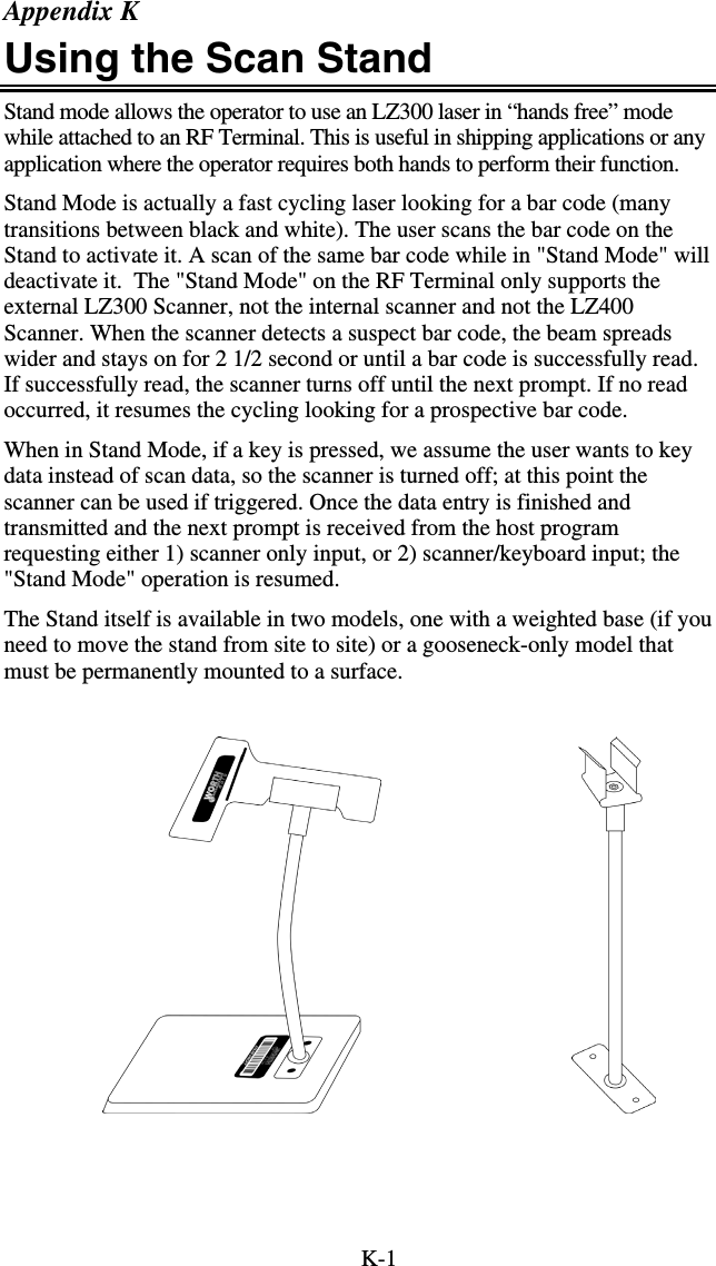
![7-3Record/Playback--->1 Assign Errors------->2 Cloning Master----->3 Cloning Receiver-->4 Pressing the “1” key takes you into the voice recording and playback function. Pressing the “2” key allows you to assign voice message numbers to error conditions. “3” and “4” allow you to clone voice messages from one RF Terminal to another. Each option is shown in detail below: Recording and Playback of Voice Messages If you respond with a “1” at the menu, you will see the following Record/Playback prompt: RECORD/PLAYBACK? KEY [R/P]? First, we will playback a message that has already been recorded. Let’s use message #01 for this example. Press the P key (for Playback) to get to the next prompt: KEY [R/P]? MESSAGE #: _ At this prompt, enter a two digit number for the message number you want to listen to. Enter “01” and then press the ENTER key. You will probably hear the “ITEM” prompt recorded at the factory unless you have edited or reset the default messages. If you heard nothing, a new message can be safely recorded in the area assigned to message # 01. After you have heard the message (or static if no message has been recorded), the RF Terminal displays the RECORD/PLAYBACK prompt again: RECORD/PLAYBACK? KEY [R/P]? To record a message, get out the microphone (no, it’s not an earphone) shipped with the RF Terminal and plug it into the AUX jack located next to the POWER jack on the bottom of the RF Terminal. Answer the prompt by pressing the R key to record a message. The bottom line of the display now reads: MESSAGE #: _ Enter the message number you are going to record. For this example, enter message #03 (by default this is a blank message) by pressing 03, then the ENTER key. The RF Terminal screen now shows: HIT ANY KEY TO START RECORDING](https://usermanual.wiki/Worthdata/LT802/User-Guide-599054-Page-52.png)
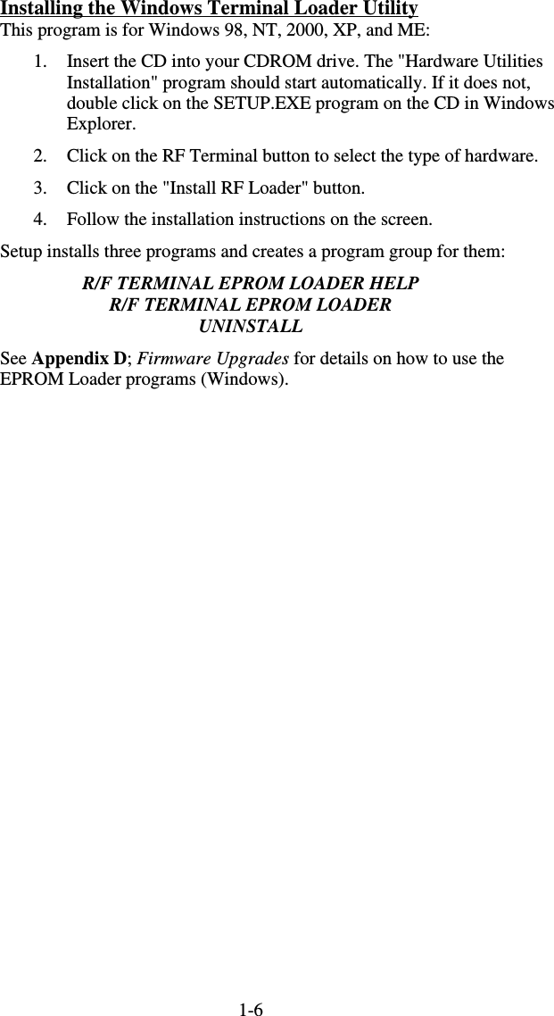
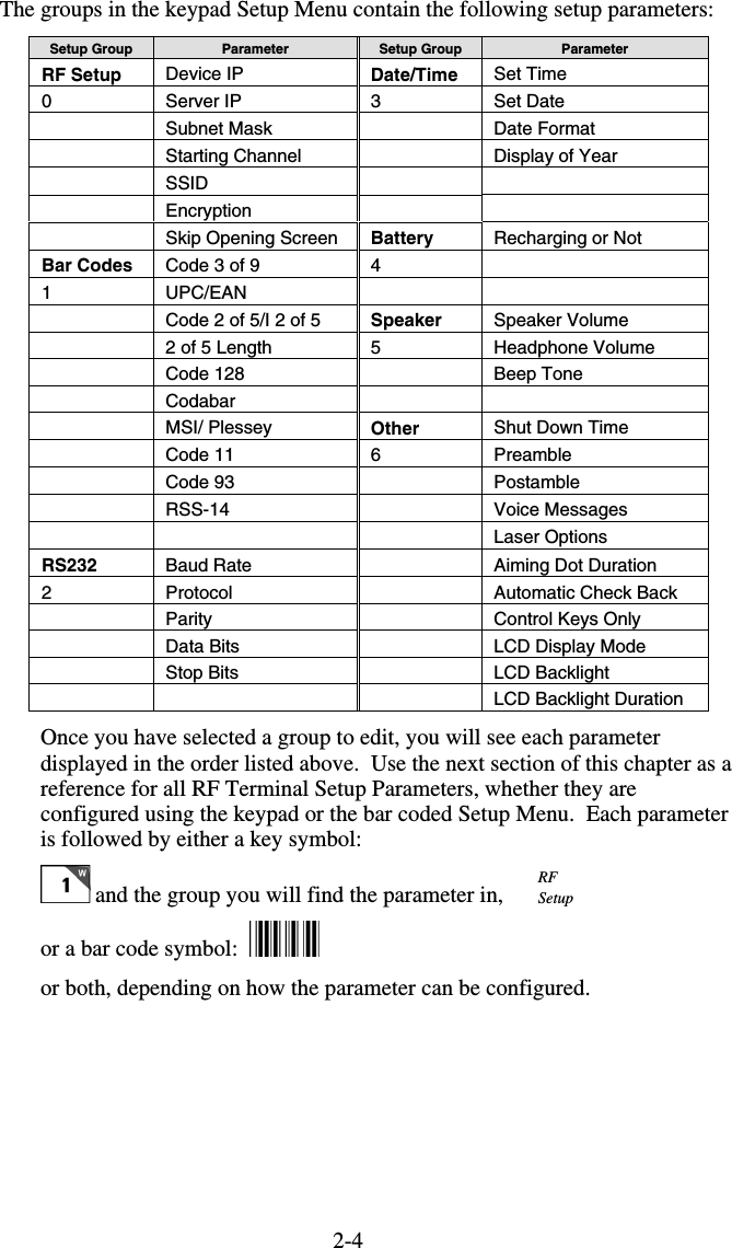
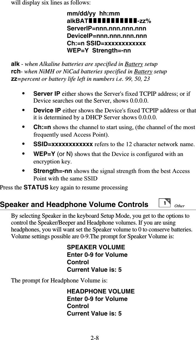
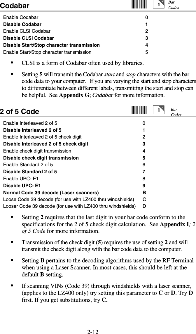
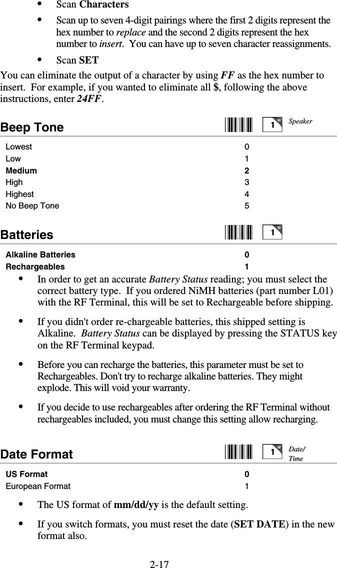
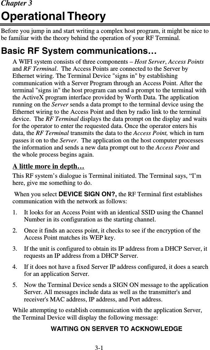
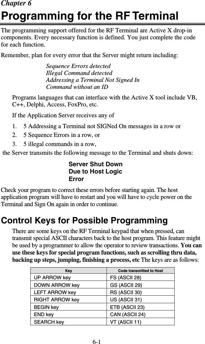
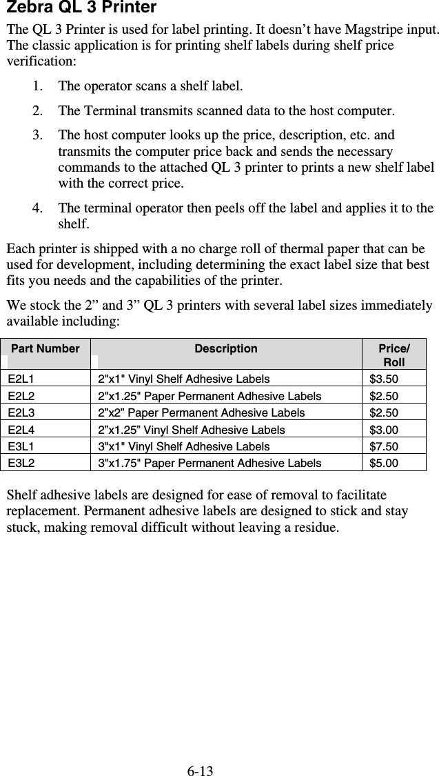
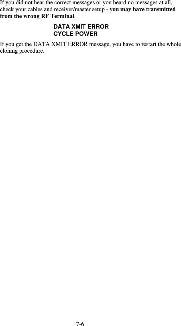
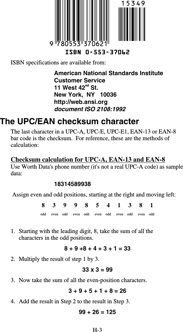
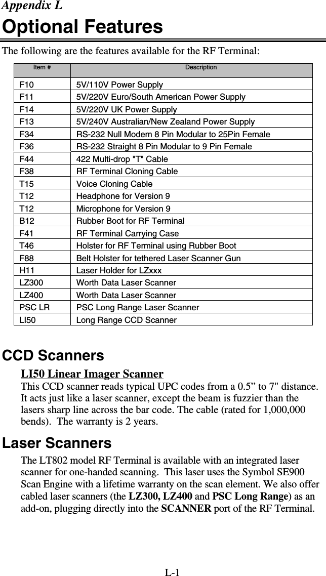
![7-4To record a message, press any key and hold it down. When you release the key, immediately start speaking into the microphone. To practice, let’s record something in message #03. Get ready to say ITEM (in English or your language) into the microphone of the RF Terminal. When ready, press the ENTER key and the instant you release it, speak ITEM into the microphone. Remember to speak clearly – you have plenty of time to say ITEM in ½ second. When the message time is over, you will hear two beeps. The display is back to the RECORD/PLAYBACK prompt: RECORD/PLAYBACK? KEY [R/P]? Now you’re ready to listen to your first recording. Press the P key and key in 03 for the message number. Do not be discouraged if you didn’t record the entire message. Our first attempt produced “EM” in a very frantic tone of voice. Practice speaking clearly and calmly (think of the poor guy who has to hear it 10,000 times next week) as soon as the key is released. You will get the hang of it with just a little practice. That is the way all messages – prompts and errors - are recorded. If you are not sure which message numbers are blank, you can listen to messages until you find a blank for recording. The host computer relies on the fact that the voice messages are stored in the RF Terminal itself and not generated by the host. The host computer will trigger the broadcast of a voice message by sending a prompt to the RF Terminal that tells it which message number to play. If the host thinks that message #05 is STOP when it’s really GO, it can cause confusion for the operator. That is why it is important to keep track of what messages are recorded where. Assigning Error Messages Error Messages are recorded the same way other messages are - by going into RECORD/PLAYBACK, selecting a message number and recording a voice message. The RF Terminal comes from the factory with some voice prompts and error messages pre-recorded. You can change any of these messages but keep in mind that the error conditions are hardware-related and that the voice error messages they are linked to are fixed. For example, the “Low Batteries” message is located at message #31. Whenever the RF Terminal detects very low batteries, it will play message #31, regardless of what is recorded there. You could record “Happy Birthday” and the RF Terminal would broadcast it any time it detected the low battery condition. To avoid confusion, try to keep the error messages somewhat related to the error condition they represent.](https://usermanual.wiki/Worthdata/LT802/User-Guide-599054-Page-53.png)
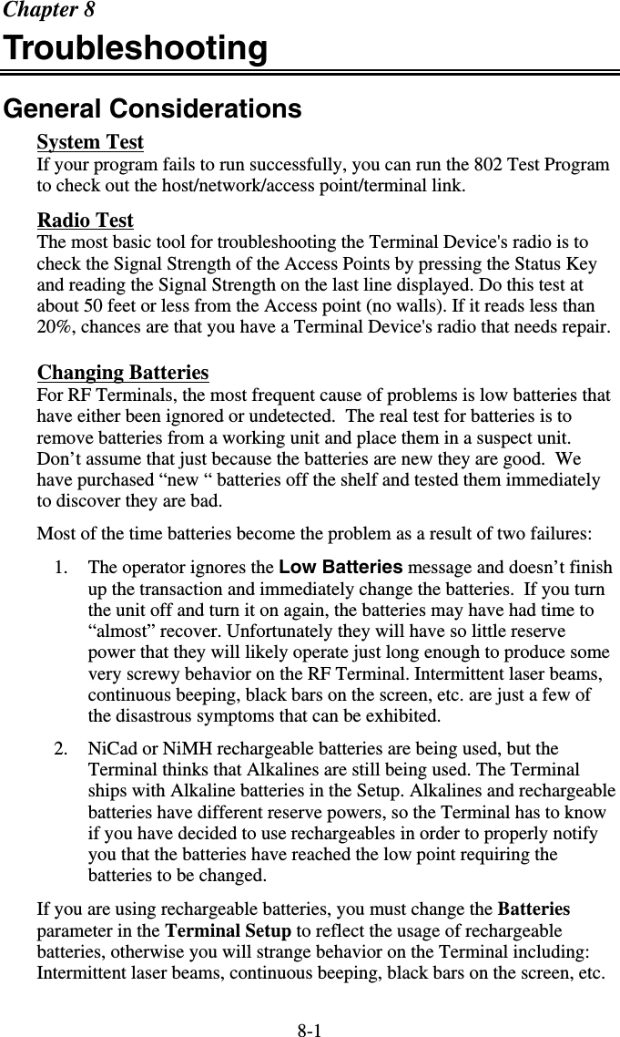
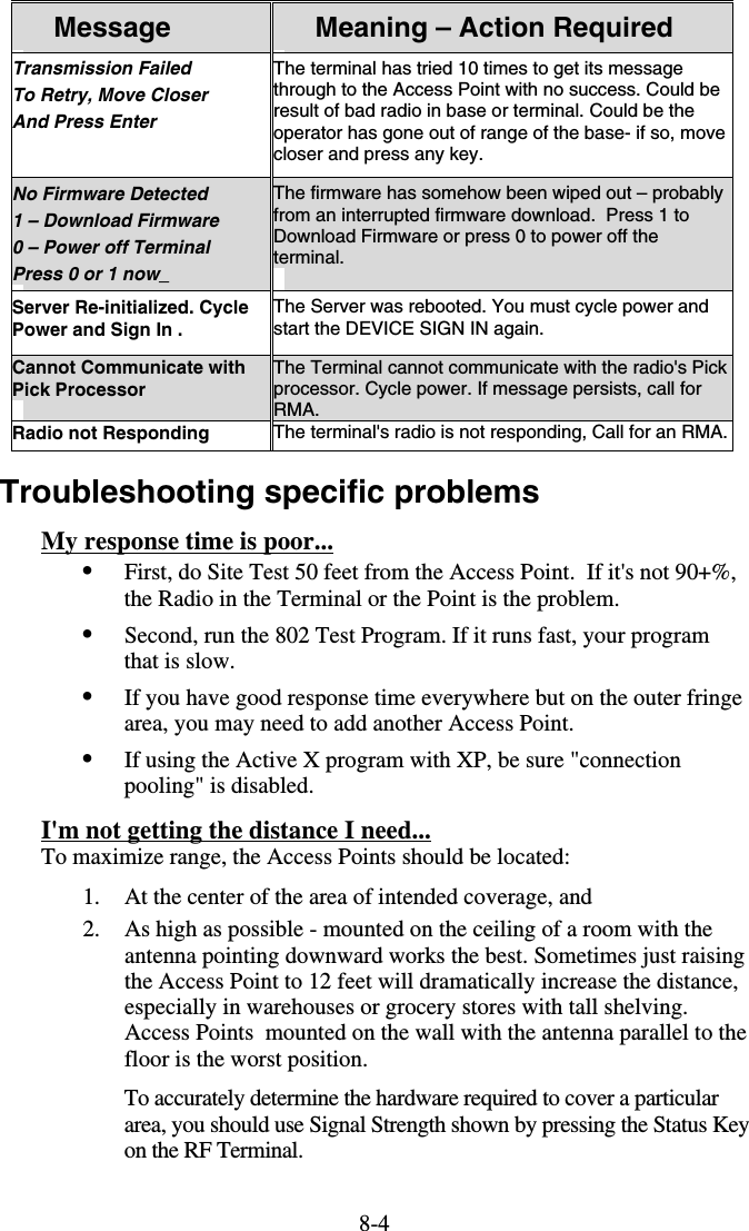
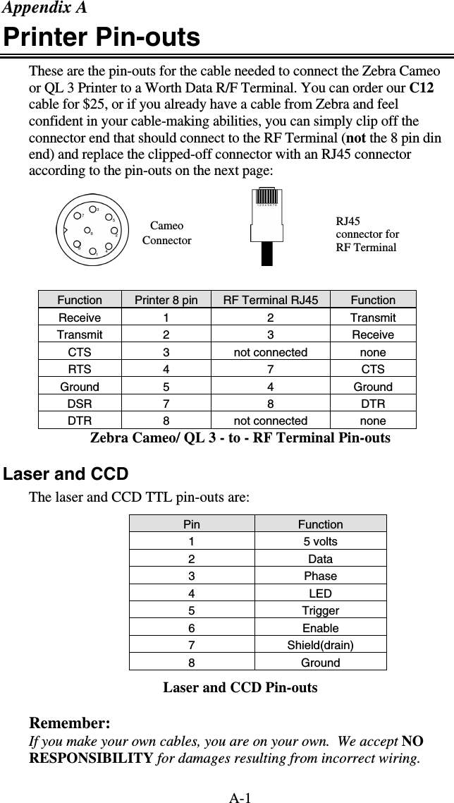
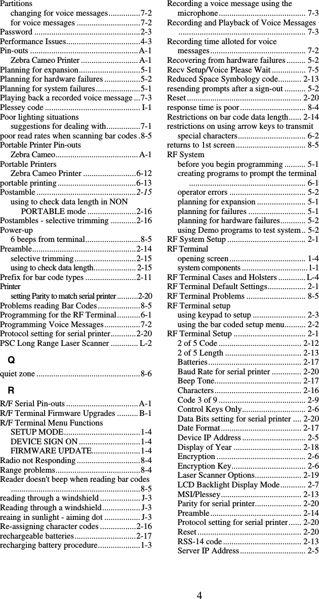
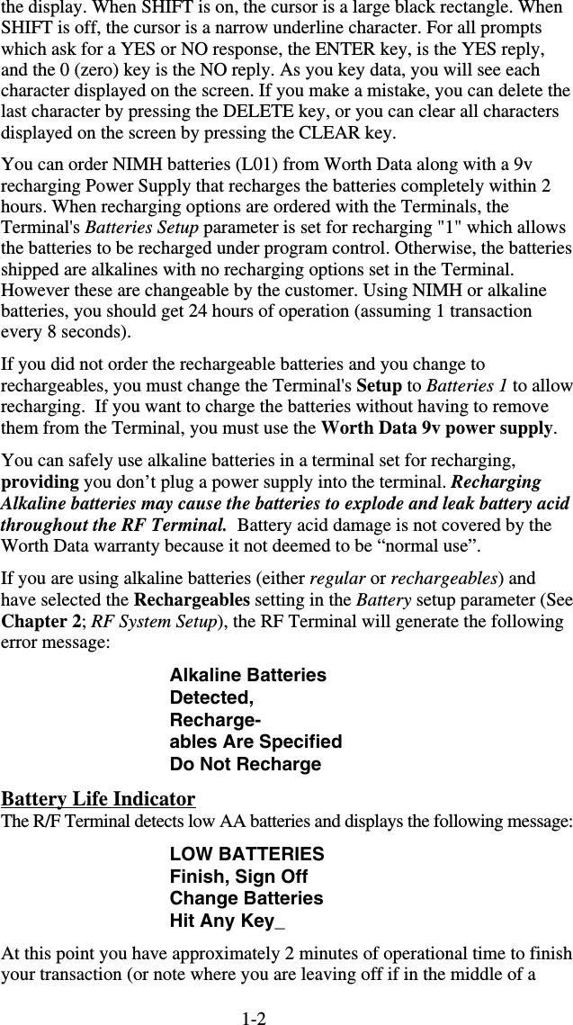
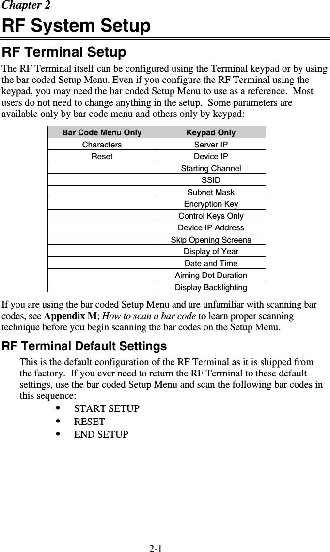
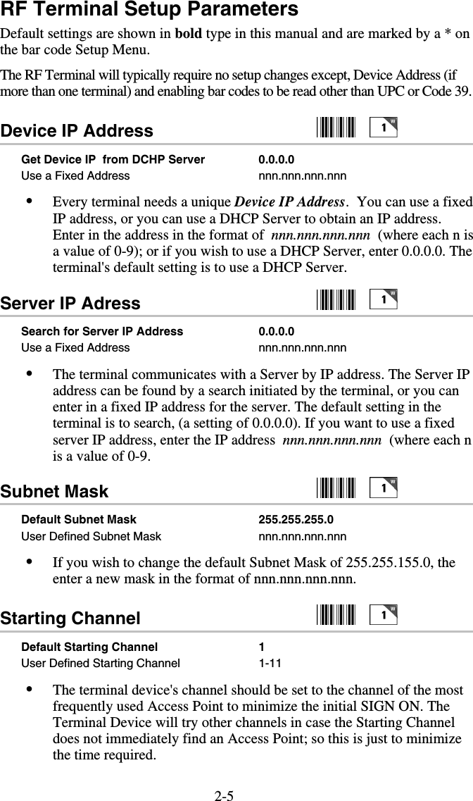
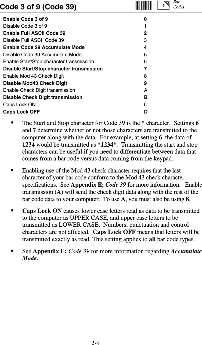
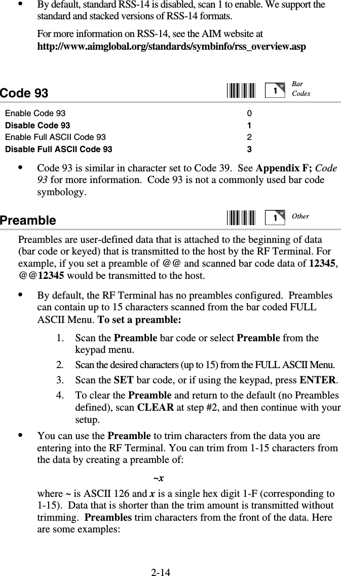
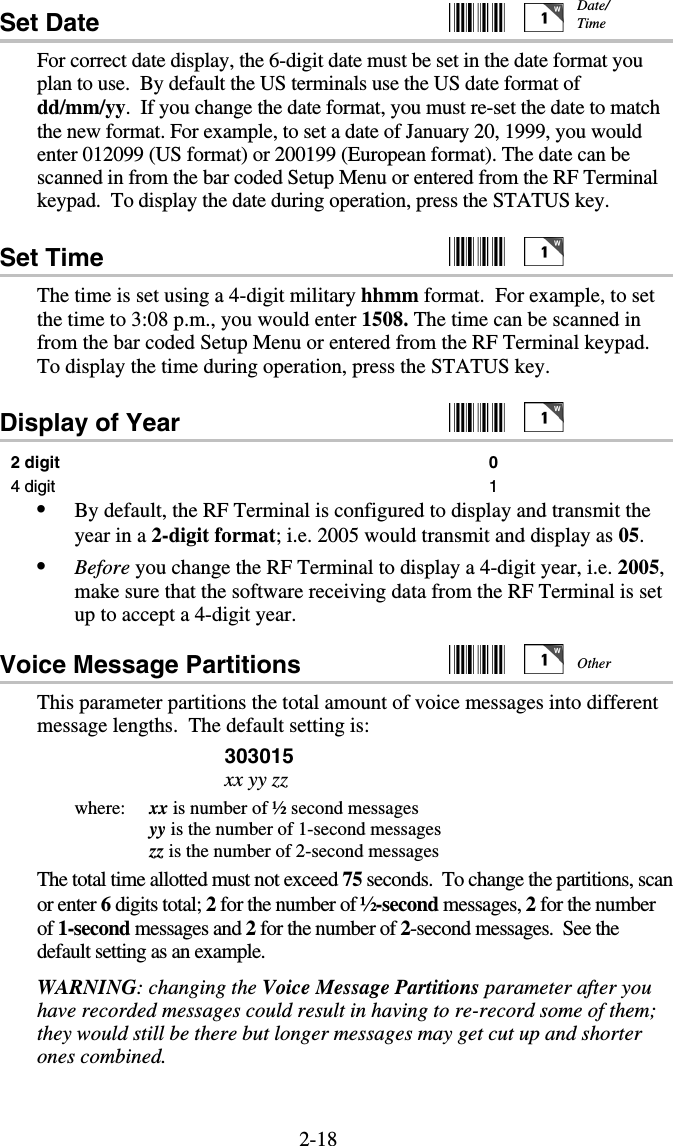
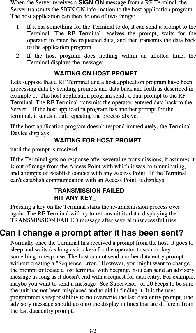
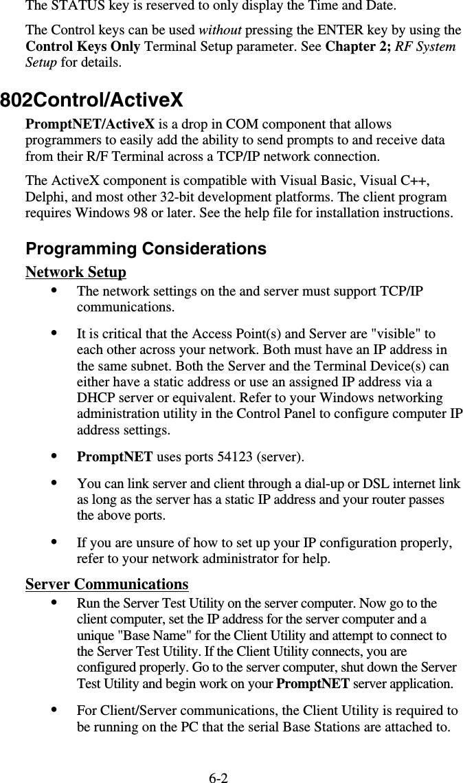
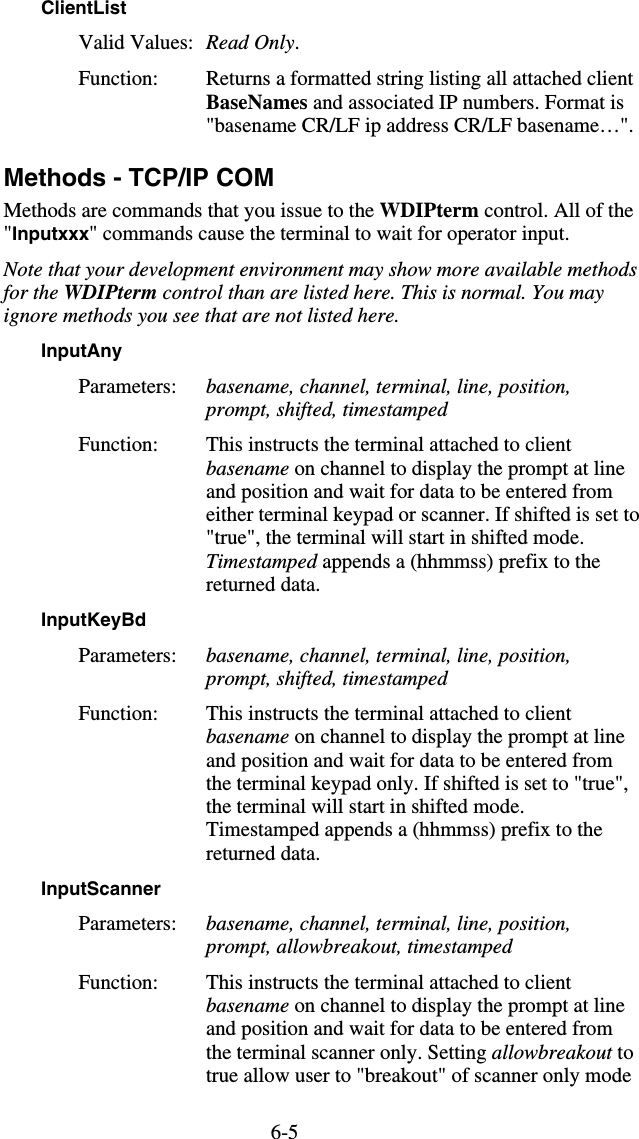
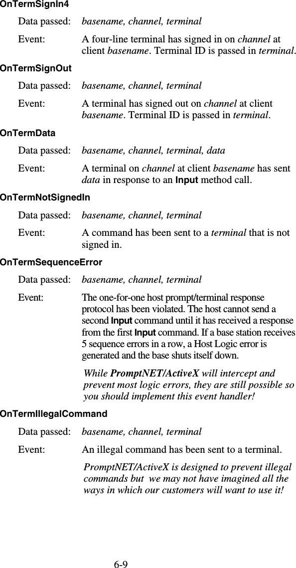
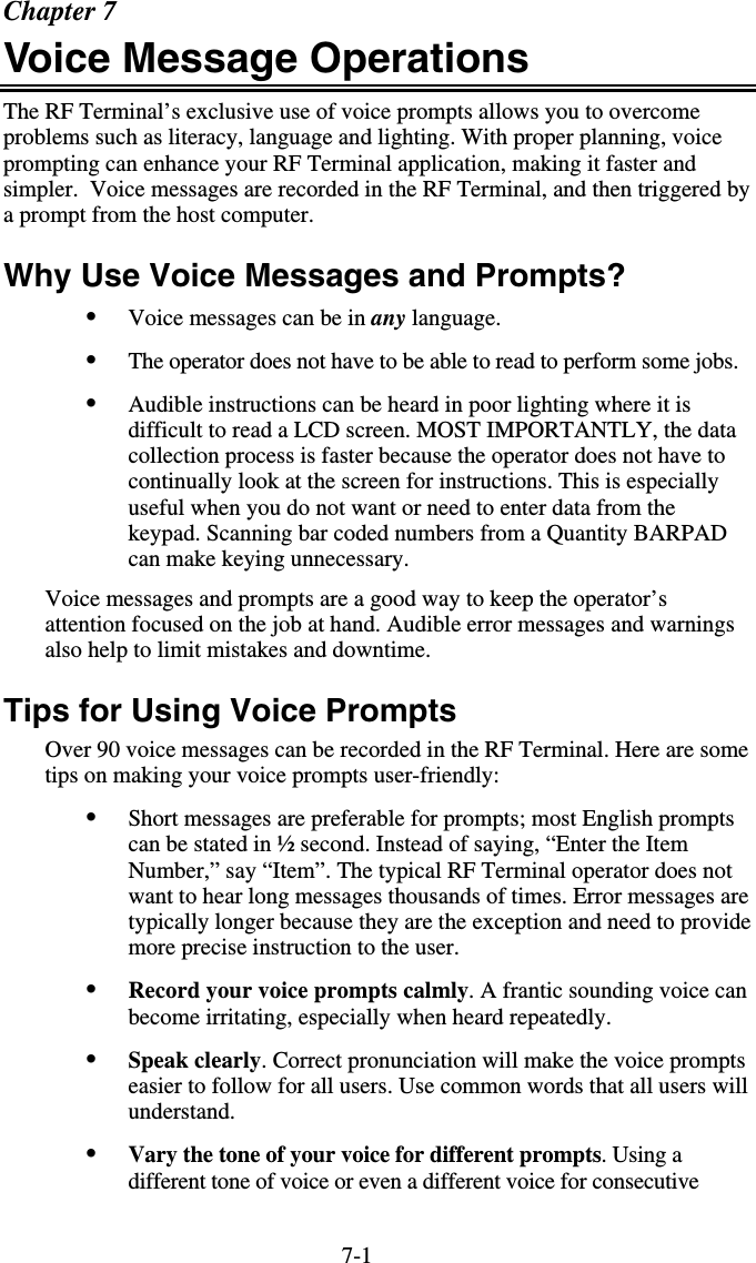
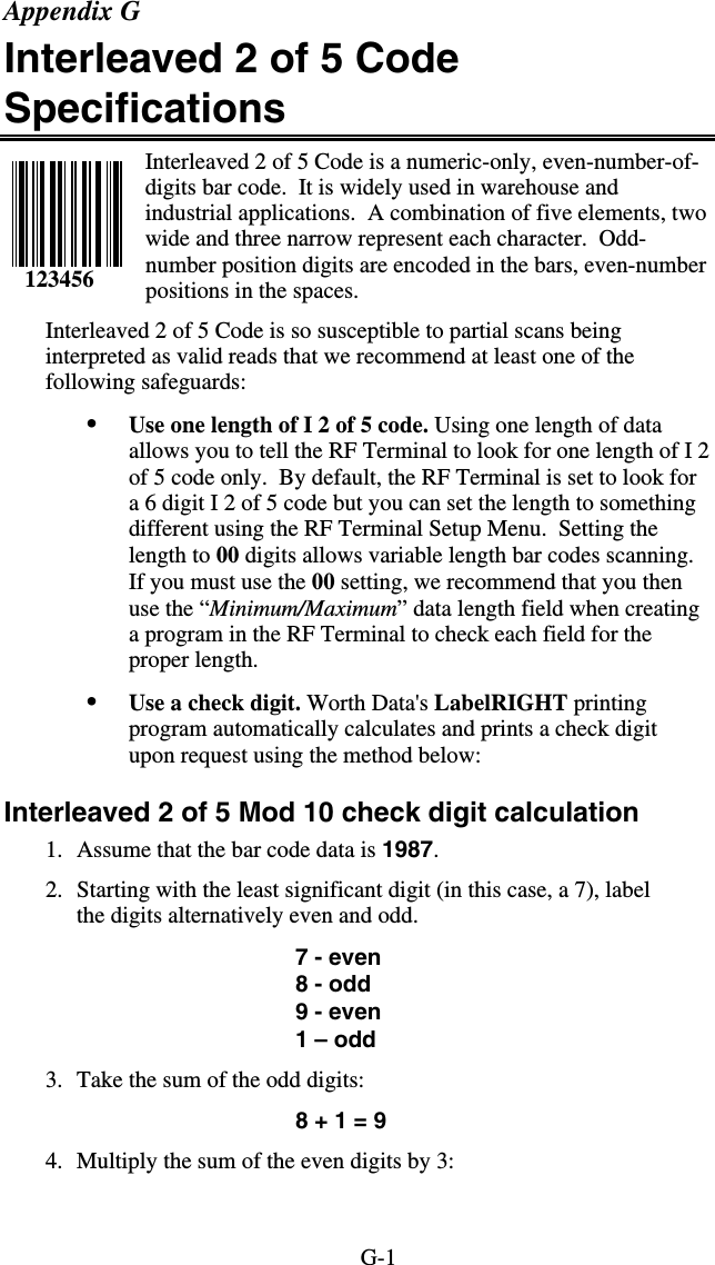
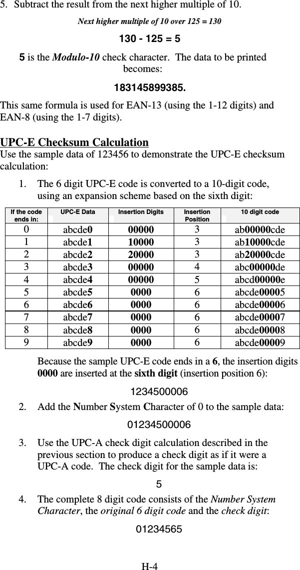
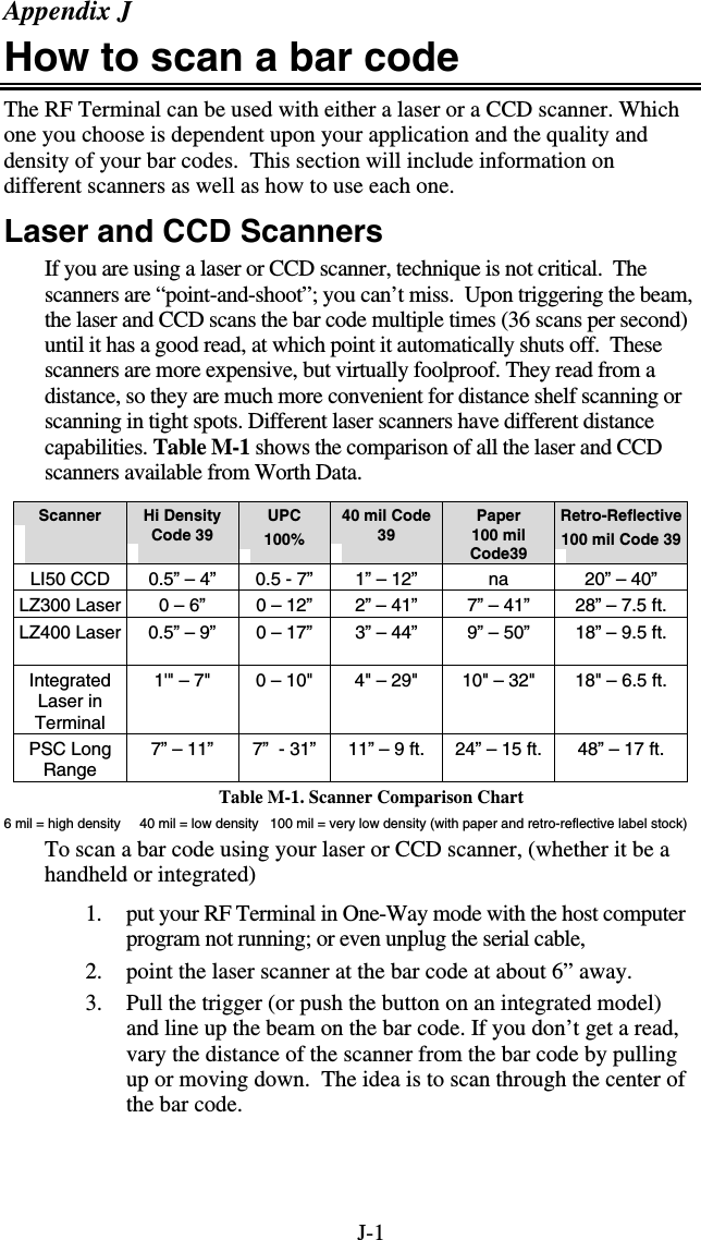
![C-3 Full ASCII Extension to Code 39 "Full-ASCII Code 39" expands the Code 39 character set to include all 128 ASCII characters. Symbols 0-9, A-Z and punctuation characters and are identical to their Code 39 representations. Lower-case letters, additional punctuation characters, and control characters are represented by sequences of two Code 39 characters. This table depicts the Full ASCII character set as a function of Code 39 characters: ASCII Code 39 ASCII Code 39 ASCII Code 39 ASCII Code 39 NUL %U SP Space @ %V ‘ %W SOH $A ! /A A A a +A STX $B “ /B B B b +B ETX $C # /C C C c +C EOT $D $ /D D D d +D ENQ $E % /E E E e +E ACK $F & /F F F f +F BEL $G ‘ /G G G g +G BS $H ( /H H H h +H HT $I ) /I I I i +I LF $J * /J J J j +J VT $K + /K K K k +K FF $L , /L L L l +L CR* $M - - or /M M M m +M SO $N . . or /N N N n +N SI $O / /O O O o +O DLE $P 0 0 or /P P P p +P DC1 $Q 1 1 or /Q Q Q q +Q DC2 $R 2 2 or /R R R r +R DC3 $S 3 3 or /S S S s +S DC4 $T 4 4 or /T T T t +T NAK $U 5 5 or /U U U u +U SYN $V 6 6 or /V V V v +V ETB $W 7 7 or /W W W w +W CAN $X 8 8 or /X X X x +X EM $Y 9 9 or /Y Y Y y +Y SUB $Z : /Z Z Z z +Z ESC %A ; %F [ %K { %P FS %B < %G \ %L | %Q GS %C = %H ] %M } %R RS %D > %I ^ %N ~ %S US %E ? %J _ %O DEL %T, %X Full ASCII Table](https://usermanual.wiki/Worthdata/LT802/User-Guide-599054-Page-69.png)
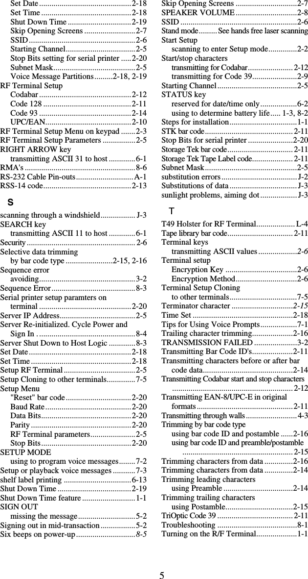
![F-1 Appendix F Code 128 Specifications Code 128 is a very powerful bar code, combining an extensive character set and variable length with compactness and error checking. The character set contains all 128 ASCII characters with each character made up of three bars and three spaces. Each element (bar or space) varies from one to four units in width, totaling 11 units of width per character. Code 128 contains two levels of error checking: • Each character is checked for internal parity, and • The last character is a checksum. Code 128 has three subsets, A, B and C. Subset A contains alphanumeric characters and unprintable control characters, subset B contains alphanumeric characters plus printable control characters and subset C contains only numeric characters and uses a 2-character encoding scheme to create a more compact bar code. Code 128 uses an internal Mod 103 check character that is not displayed by the bar code reader. Code 128 bar codes can be made up of only one subset or may be a combination of several. The Code 39 features of Accumulate Mode, Caps Lock ON and Caps lock OFF also apply to Code 128. UCC-128/ EAN-128 UCC-128/EAN-128 Code is a subset of Code 128 adopted by the UCC and EAN council’s for use as a shipping label symbology. UCC/EAN-128 bar codes always start with a Function Code 1 character. In addition, a Function Code 1 character terminates all variable length fields unless they are the last field in the bar code. The RF Terminal outputs the following for the special function codes and start sequences: ]C1 Start C/Function Code 1 ^] (GS) Function Code 1 as a variable string terminator If UCC/EAN 128 is enabled, the reader looks for the Start C/Function Code 1 to indicate a UCC/EAN 128 bar code. The UCC Serial Shipping Container Code specification calls for a 19 digit UCC/EAN 128 code with an additional Mod 10 Check digit (20 digits in all). The Mod 10 Check digit is calculated the same as the Interleaved 2 of 5 example in Appendix D. It is the data length as well as the MOD 10 check digit that distinguishes the UCC Serial Shipping Container Code from other UCC /EAN 128 bar codes. 12345](https://usermanual.wiki/Worthdata/LT802/User-Guide-599054-Page-75.png)
![F-2Scanning the appropriate bar codes on the RF Terminal Setup Menu enables UCC/EAN 128; or you can use the keypad in the PROGRAMMING MODE “Change Setup” option. If UCC/EAN 128 is enabled, you will be able to read both standard Code 128 bar codes as well as the UCC/EAN 128 bar codes with the Function 1 character and the Mod 10 check character. UCC-128 Shipping Container Code If UCC/EAN-128 is enabled on the R/F Terminal reader, all Function 1 codes are transmitted as ]C1. In addition, should you be reading a 20 digit Shipping Serial Container code, the Mod 10 check digit is also compared with the computed Mod 10 value to give further assurance of no substitutions. The UCC/EAN-128 Shipping Serial Container Code is a subset of UCC-128 or EAN-128 adopted for voluntary marking of shipping boxes with the exact serial number of the box, (used with EDI typically to identify a specific boxes contents. The code consists of the following format: Start C not transmitted Function Code 1 transmitted 2 Digit Qualifier transmitted 7 Digit Data Portion transmitted 1 Digit Mod 10 Check Digit* transmitted- 1 Digit Modulus 103 not transmitted Stop Code not transmitted *Calculated using 19digits-UPC method The UCC 128 specification is used extensively by the retail industry. If you have a requirement for a UCC 128 Serial Shipping Container bar code, be sure to follow the specification as closely as possible as many vendors will impose fines for non-conformance. For more information on UCC 128, contact the Uniform Code Council at: Uniform Code Council, Inc. 7887 Washington Village Drive, Suite 300 Dayton, OH 45459 937-435-3870 937-435-7317 info@uc-council.org 8:00 a.m. to 6 p.m. EST Specifications are available online at:http://www.uc-council.org](https://usermanual.wiki/Worthdata/LT802/User-Guide-599054-Page-76.png)
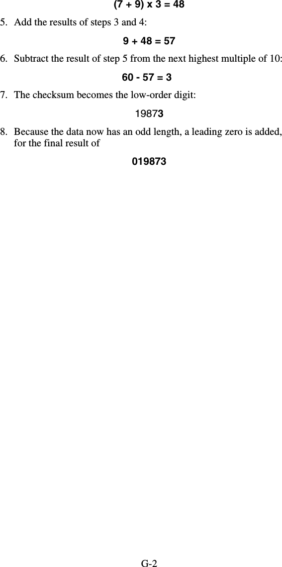
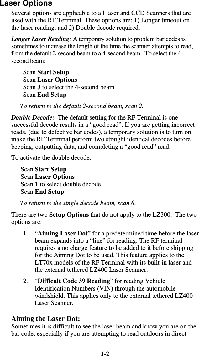
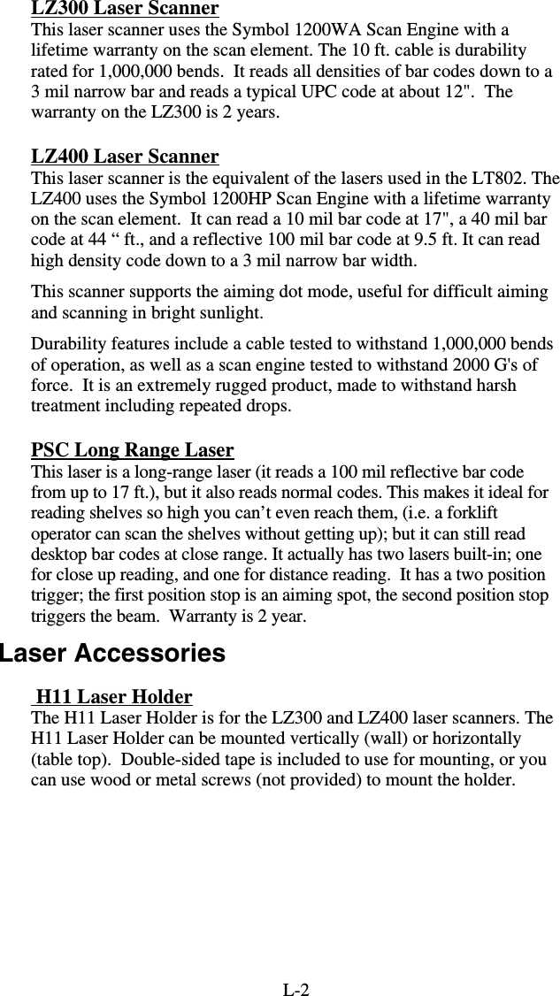
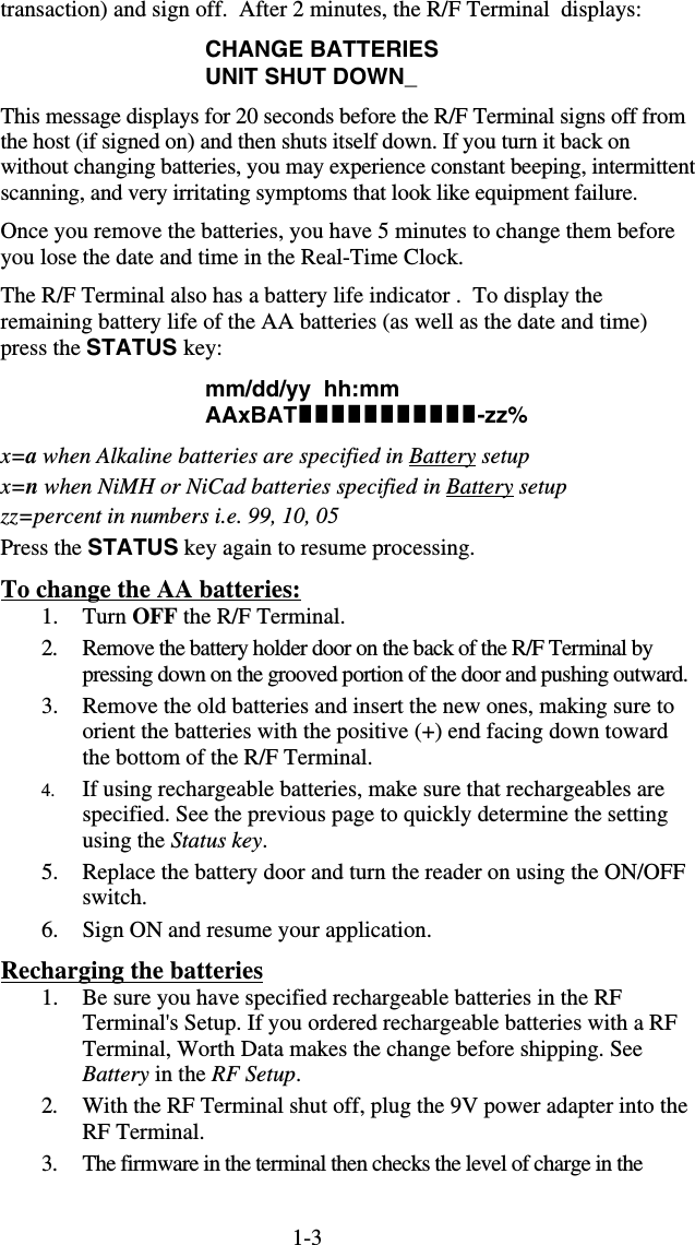
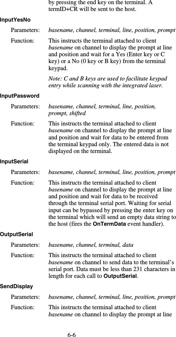
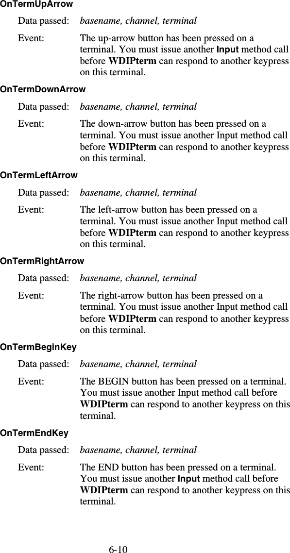
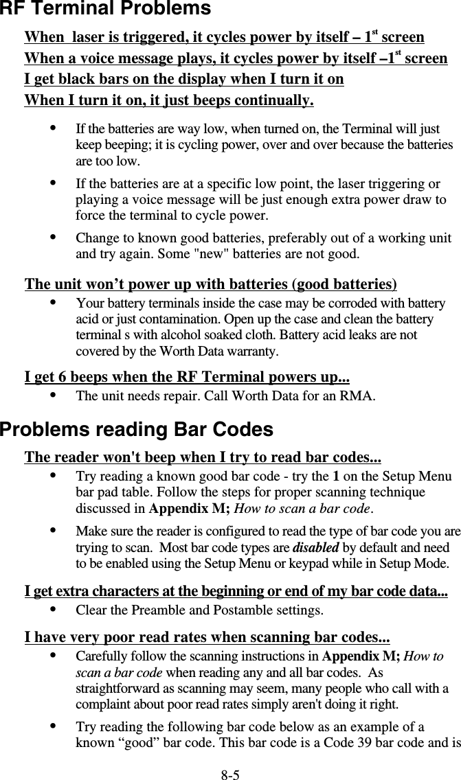
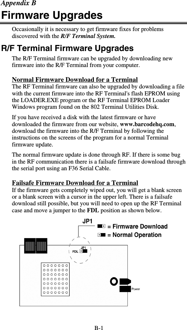
![M-1 Appendix M ASCII Code Equivalent Table The 128 ASCII codes, their 3-digit decimal equivalents and 2-digit hex equivalents are detailed in the below table. char hex 3 digit ASCII char hex 3 digit ASCII char hex 3 digit ASCII char hex 3 digit ASCII NUL 00 000 SP 20 032 @ 40 064 ‘ 60 096 SOH 01 001 ! 21 033 A 41 065 a 61 097 STX 02 002 " 22 034 B 42 066 b 62 098 ETX 03 003 # 23 035 C 43 067 c 63 099 EOT 04 004 $ 24 036 D 44 068 d 64 100 ENQ 05 005 % 25 037 E 45 069 e 65 101 ACK 06 006 & 26 038 F 46 070 f 66 102 BEL 07 007 ' 27 039 G 47 071 g 67 103 BS 08 008 ( 28 040 H 48 072 h 68 104 HT 09 009 ) 29 041 I 49 073 i 69 105 LF 0A 010 * 2A 042 J 4A 074 j 6A 106 VT 0B 011 + 2B 043 K 4B 075 k 6B 107 FF 0C 012 , 2C 044 L 4C 076 l 6C 108 CR 0D 013 - 2D 045 M 4D 077 m 6D 109 SO 0E 014 . 2E 046 N 4E 078 n 6E 110 SI 0F 015 / 2F 047 O 4F 079 o 6F 111 DLE 10 016 0 30 048 P 50 080 p 70 112 DC1 11 017 1 31 049 Q 51 081 q 71 113 DC2 12 018 2 32 050 R 52 082 r 72 114 DC3 13 019 3 33 051 S 53 083 s 73 115 DC4 14 020 4 34 052 T 54 084 t 74 116 NAK 15 021 5 35 053 U 55 085 u 75 117 SYN 16 022 6 36 054 V 56 086 v 76 118 ETB 17 023 7 37 055 W 57 087 w 77 119 CAN 18 024 8 38 056 X 58 088 x 78 120 EM 19 025 9 39 057 Y 59 089 y 79 121 SUB 1A 026 : 3A 058 Z 5A 090 z 7A 122 ESC 1B 027 ; 3B 059 [ 5B 091 { 7B 123 FS 1C 028 < 3C 060 \ 5C 092 | 7C 124 GS 1D 029 = 3D 061 ] 5D 093 } 7D 125 RS 1E 030 > 3E 062 ^ 5E 094 ~ 7E 126 US 1F 031 ? 3F 063 _ 5F 095 DEL 7F 127 Full ASCII Equivalent Table](https://usermanual.wiki/Worthdata/LT802/User-Guide-599054-Page-95.png)