Wuerth Elektronik eiSos and Co KG BLUENICECOM3 Bluetooth module BlueNiceCom III User Manual Englisch BlueNiceCom III V1 4
AMBER Wireless GmbH Bluetooth module BlueNiceCom III Englisch BlueNiceCom III V1 4
User Manual
Manual
BlueNiceCom III
V1.4
Stand November 2004
AMBER wireless GmbH
Albin-Köbis-Straße 18
51147 Köln
Tel. 02203-6991950
Fax 02203-459883
eMail info@amber-wireless.de
Internet www.amber-wireless.de

Stand November 2004, Version 1.4
Technische Änderungen vorbehalten
AMBER wireless GmbH, Tel. 02203-6991950, Fax 02203-459883
Email info@ amber-wireless.de Internet www.amber-wireless.de
Inhaltsverzeichnis
1 Allgemein .......................................................................................Fehler! Textmarke nicht definiert.
2 Technische Daten:.........................................................................Fehler! Textmarke nicht definiert.
3 Anschlussbelegung :..........................................................................................................................4
4 Abmessungen: ...................................................................................................................................5
5 Hinweise zum Layout:......................................................................................................................6
Stand November 2004, Version 1.4
Technische Änderungen vorbehalten
AMBER wireless GmbH, Tel. 02203-6991950, Fax 02203-459883
Email info@ amber-wireless.de Internet www.amber-wireless.de
1 General
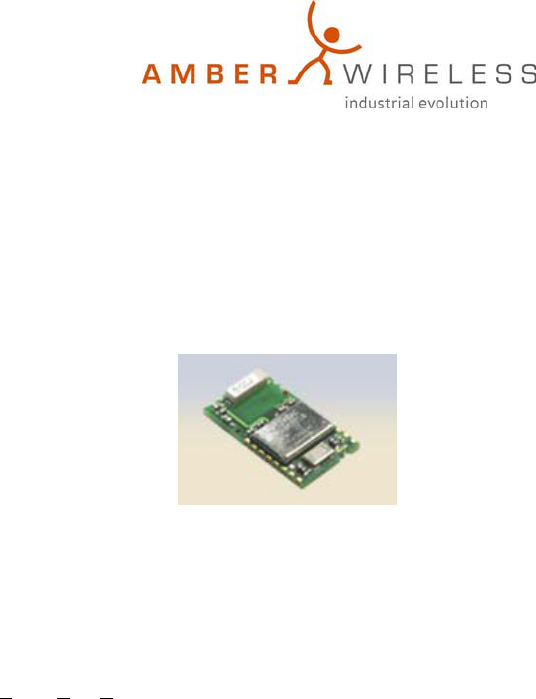
BlueNiceCom III
Bluetooth-Modul with UART-interface and integrated Chip-antenna
• Bluetooth Class 2 Modul
• Serial Port Profile (SPP)
• UART interface
• Integrated chip-antenne
• GAP & SDP support
AMBER wireless provides with the BlueNiceCom III a Bluetooth-module with an integrated chip-
antenna, based on LMX9820 from National Semiconductor. This compact and inexpensive Bluetooth-
version is qualified for a serial data transmission.
BlueNiceCom III comes with a SPP profile (Serial Port Profile) and works with other Bluetooth modules
which support the same profile. Through the serial UART interface the BlueNiceCom will be connected
to a processor or a direct to a system, according to the application.
Via an external processor or host (PC) all further available application profiles could be set on the SPP-
profile, for example: Dial up Networking Profile, Fax Profile, LAN Access Profile.
The module has an integrated chip-antenna and can placed into a circuit like a SMD-part.
The controlling and setting is raised by a host processor. The module can be integrated easily in a system.
According to the application and the settings the BlueNiceCom II can be work as a stand-alone-slave-
module.
For a cable replacement or a point-to-multipoint (piconet) application a controlling through a processor is
necessary. Up to 3 slaves could be managed by a master module.
2 Technical data:
Voltage supply 2,85V to 3,6V
Current consumption typ. 65 mA
RF output typ. 0 dBm
Rx Sensitivity typ. –77dBm
Datarate UART: 9,6 kbps to 115kbps
Interface according to LMX9820
Operating temperature -10° bis +55°, optional an extended temperature range is possible
Dimension 27,5 x 16 x 3,5 mm
Miscellaneous All further technical datas according to the LMX9820 Modul of
National Semiconductor
Order number BlueNiceCom III
Stand November 2004, Version 1.4
Technische Änderungen vorbehalten
AMBER wireless GmbH, Tel. 02203-6991950, Fax 02203-459883
Email info@ amber-wireless.de Internet www.amber-wireless.de
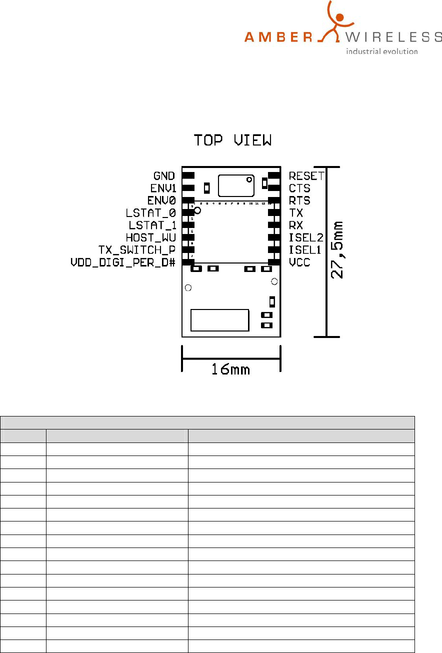
3 Pin assignment :
ST1
Pin Nr. Signal of BlueNiceCom III Signal of LMX 9820
1 VCC Voltage supply (2,85V bis 3,6V)
2 ISEL1 Input Isel1 of LMX9820
3 ISEL2 Input Isel2 of LMX9820
4 RX Input Uart_rx of LMX9820
5 TX Output Uart_tx of LMX9820
6 RTS Output Uart_rts of LMX9820
7 CTS Input Uart_cts of LMX9820
8 RESET Input Reset_b and Reset_5100 of LMX9820
9 GND Ground
10 ENV1 Input Env1 of LMX9820
11 ENV0 Input Env0 of LMX9820
12 LSTAT_0 Output Lstat_0 of LMX9820
13 LSTAT_1 Output Lstat_1 of LMX9820
14 HOST_WU Output Host_wu of LMX9820
15 TX_SWITCH_P Output TX_Switch_P of LMX9820
16 VDD_DIGI_PWR_D# Input VDD_DIGI_PWR_D# of LMX9820
The signal level correspond to the power supply (2,85V bis 3,6V) of BlueNiceCom III and must be
aligned if the Hostsystem has a different signal level.
Antenne
Stand November 2004, Version 1.4
Technische Änderungen vorbehalten
AMBER wireless GmbH, Tel. 02203-6991950, Fax 02203-459883
Email info@ amber-wireless.de Internet www.amber-wireless.de
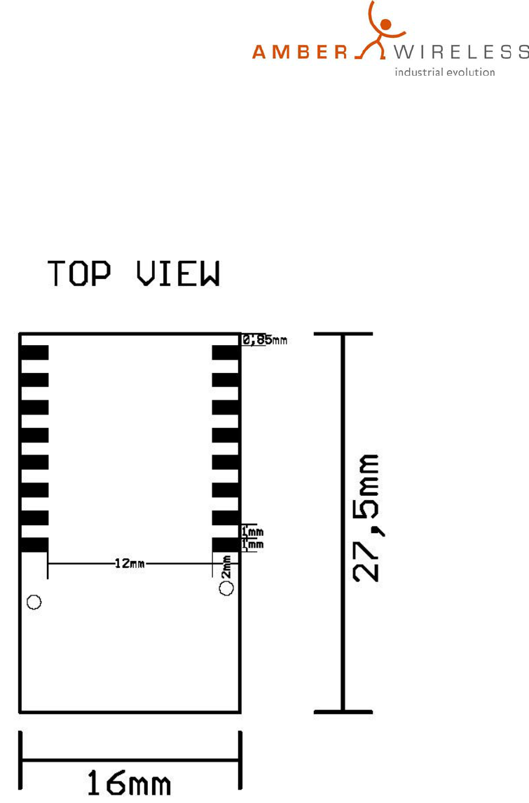
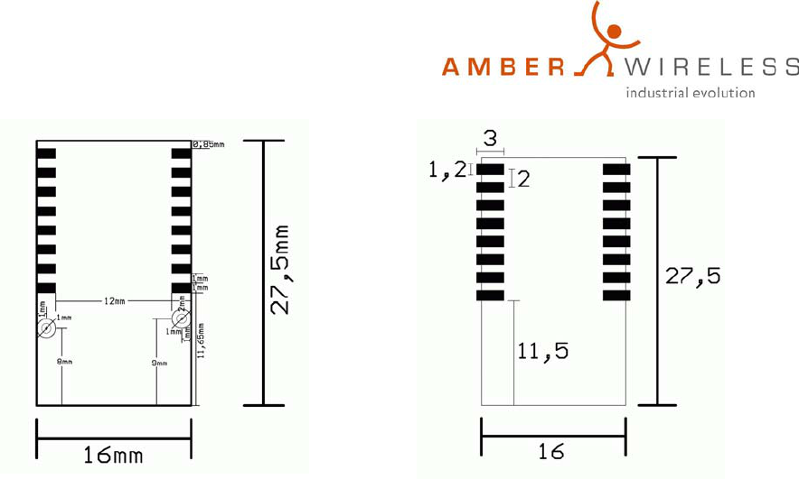
4 Dimession:
BlueNiceCom III has 1mm x 2mm soldering pads with a raster of 2mm to be solder direct on a
motherboard.
Stand November 2004, Version 1.4
Technische Änderungen vorbehalten
AMBER wireless GmbH, Tel. 02203-6991950, Fax 02203-459883
Email info@ amber-wireless.de Internet www.amber-wireless.de
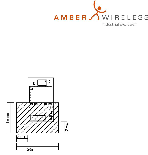
5 Details for Layout:
To achieve the maximum of range no metall has to be near or under the antenna. The antenna should have
a distance of 8mm to any gound, strip line or component. Most suitable is to place the antenna at the
margin of the motherboard.
The figure shows the area which should be free of metal (ground, strip line, components, etc..).
The area off 12mm between the soldering pads on the bottom side should (e.g. with adhesive tape)
additional isolated, if any strip line is under the module to avoid any short circuit.
6 Soldering & Reflow
• Reflow appropriate
• The temperature curve depends on the motherboard it´s character.
• Depending on the limit values of the components following limits are not allowed to excess-
225°C (LMX)
220°C max. 10s (Chip-antenna)
200°C max. 40s (Chip-antenna)
• Recommendation for Footprints:
Stand November 2004, Version 1.4
Technische Änderungen vorbehalten
AMBER wireless GmbH, Tel. 02203-6991950, Fax 02203-459883
Email info@ amber-wireless.de Internet www.amber-wireless.de
Abbildung 1: Bluenicecom III
Abbildung 2: Vorschlag for Footprint
Further range of products around BlueNiceCom II:
Bluetoothmodules: BlueNiceCom I & II & III
Evaluation-Kit: 1 BlueNiceCom II module; 1 2,4GHz antenna; 1 RS232 board with Sub-D-9
connector and LED´s; batteries for power supply; 1 USB-Bluetoothmodule for a
second station – to build up a Bluetooth radio link immediately, documentation and
software.
Software-Tools: C-Tools for controlling the LMX9820.
AMBER wireless GmbH reserves for itself to change the mentioned data without announcement and
takes no liability for technical inaccuracies and/or omissions.
AMBER wireless GmbH
Albin-Köbis-Straße 18
51147 Köln
Tel. 02203-6991950
Fax 02203-459883
eMail info@amber-wireless.de
Internet www.amber-wireless.de