Wulfsberg Electronics Division 2000-UHF1 UHF TRANSCEIVER User Manual 150 049106 A
Wulfsberg Electronics Division UHF TRANSCEIVER 150 049106 A
UserManual.wiki
>
Wulfsberg Electronics Division
>
2000-UHF1 User Manual
>
users manual 150 049106A
Contents
1.
users manual 150 049105A
2.
users manual 150 049106A
3.
users manual
users manual 150 049106A
Navigation menu
Upload a User Manual
Namespaces
Wiki Guide
HTML
PDF
Info
Views
User Manual
Discussion / Help
Navigation
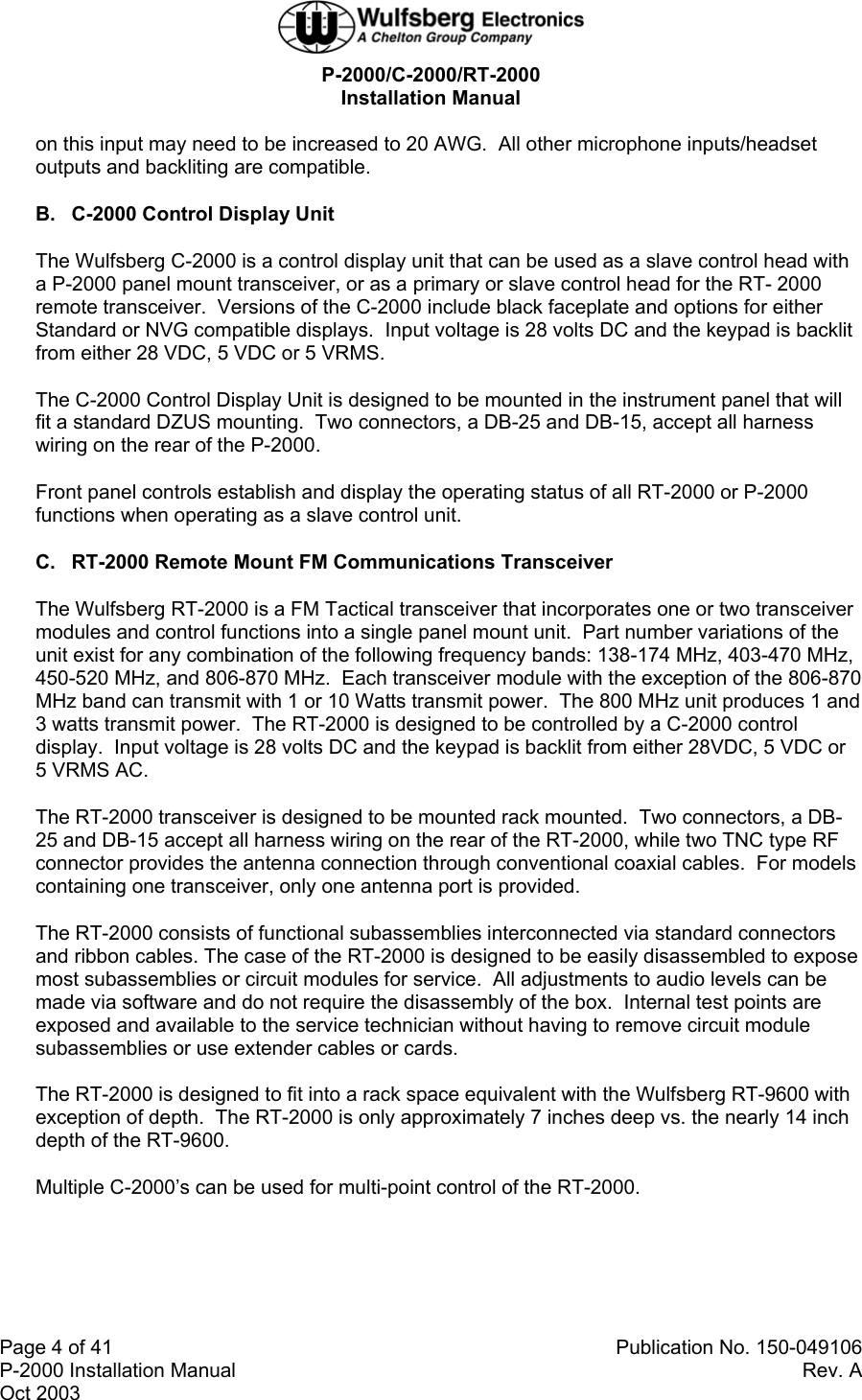
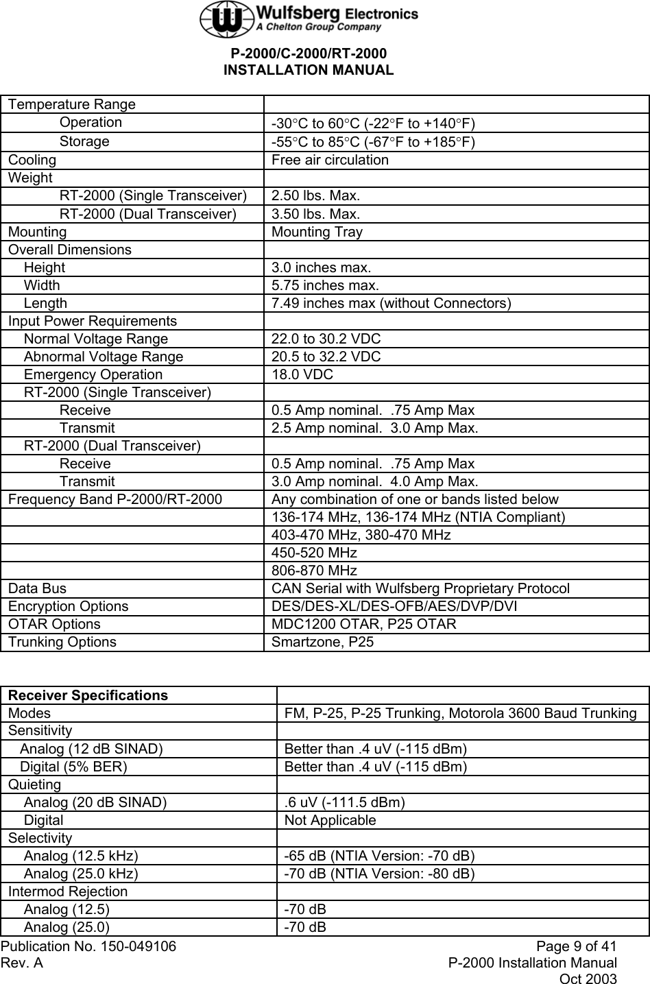
![P-2000/C-2000/RT-2000 INSTALLATION MANUAL Publication No. 150-049106 Page 5 of 41 Rev. A P-2000 Installation Manual Oct 2003 4. Technical Characteristics A. P-2000 Panel Mount Transceiver CHARACTERISTICS DESCRIPTION Certification FAA In Process (STC Helicopter and Fixed Wing Aircraft) Software DO-170B Level D Environmental DO-160D [(B4/F1)X]BAB[S/U]EXXXXXZZAZZ[J/F]M[XXC3]XXA FCC FRW-2000-(VHF,UHF-1,UHF-2, 800) Industry Canada TBD Emission Designator 156 – 158 MHz Part 80.379, 87.187(l), 16K0F3E 136 – 174 MHz Part 90.210, 16K0F3E, 11K0F3E, 8K10F1E, 8K0F1D 403 – 520 MHz Part 90.210, 16K0F3E, 11K0F3E 806 – 870 MHz Part 90, 16K0F3E, 11K0F3E, 8K10F1E, 8K0F1D Altitude 51,000 feet ASL (15,545 meters) Temperature Range Operation -30°C to 60°C (-22°F to +140°F) Storage -55°C to 85°C (-67°F to +185°F) Cooling Internal Electric Fan Weight P-2000 (Single Transceiver) 3.10 lbs. Max. P-2000 (Dual Transceiver) 3.70 lbs. Max. Mounting Dzus Height 3.0 Inches max. Width 5.75 inches max. Depth 6.40 Inches max. (Not Including Connectors) Input Power Requirements Normal Voltage Range 22.0 to 30.2 VDC Abnormal Voltage Range 20.5 to 32.2 VDC Emergency Operation 18.0 VDC P-2000 (Single Transceiver) Receive 0.5 Amp Nominal. .75 Amp Max Transmit 2.5 Amp Nominal. 3.0 Amp Max. P-2000 (Dual Transceiver) Receive 0.5 Amp nominal. 1.0 Amp Max Transmit 3.0 Amp nominal. 4.0 Amp Max. P-2000 Panel Lighting 5 VDC, 5 Vrms and 28 VDC (Voltage Sense Only) Faceplate Colors Black or Grey Channel Memory 240/255/510 Depending on options Frequency Band P-2000/RT-2000 Any combination of one or two bands listed below 136-174 MHz, 136-174 MHz (NTIA Compliant) 403-470 MHz, 380-470 MHz 450-520 MHz](https://usermanual.wiki/Wulfsberg-Electronics-Division/2000-UHF1.users-manual-150-049106A/User-Guide-368583-Page-5.png)
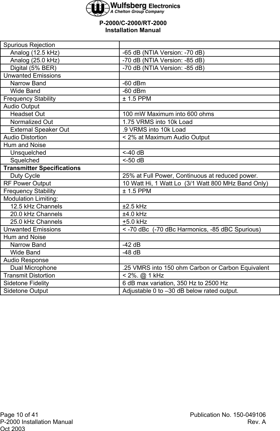
![P-2000/C-2000/RT-2000 Installation Manual Page 8 of 41 Publication No. 150-049106 P-2000 Installation Manual Rev. A Oct 2003 B. C-2000 Control Display Unit CHARACTERISTICS DESCRIPTION Certification FAA In Process (PMA/STC Helicopter and Fixed Wing Aircraft) Software DO-170B Level D Environmental DO-160D [(B4/F1)X]BAB[S/U]EXXXXXZZAZZ[J/F]M[XXC3]XXA FCC Part 15 Industry Canada Pending Altitude 51,000 feet ASL (15,545 meters) Temperature Range Operation -30°C to 60°C (-22°F to +140°F) Storage -55°C to 85°C (-67°F to +185°F) Cooling Internal Electric Fan Weight 2.00 lbs. Max. Mounting Dzus Overall Dimensions Height 3.0 Inches max. Width 5.75 inches max. Depth 6.40 inches max. (without Connectors) Input Power Requirements Normal Voltage Range 22.0 to 30.2 VDC Abnormal Voltage Range 20.5 to 32.2 VDC Emergency Operation 18.0 VDC Input Current 0.5 Amp nominal. 1.0 Amp Max Panel Lighting 5 VDC, 5 Vrms and 28 VDC (Voltage Sense Only) Faceplate Colors Black or Grey Display Options LCD Color or LCD Color with NVG compatibility Channel Memory 240/255/510 Depending on options Data Bus CAN Serial with Wulfsberg Proprietary Protocol C. RT-2000 Remote Mount Transceiver CHARACTERISTICS DESCRIPTION Certification FAA In Process (PMA/STC Helicopter and Fixed Wing Aircraft) Software DO-170B Level D Environmental DO-160D [(B4/F1)X]BAB[S/U]EXXXXXZZAZZ[J/F]M[XXC3]XXA FCC Pending FRW-2000-(VHF,UHF-1,UHF-2, 800) Industry Canada Pending Emission Designator 156 – 158 MHz Part 80.379, 87.187(l), 16K0F3E 136 – 174 MHz Part 90.210, 16K0F3E, 11K0F3E, 8K10F1E, 8K0F1D 403 – 520 MHz Part 90.210, 16K0F3E, 11K0F3E 806 – 870 MHz Part 90, 16K0F3E, 11K0F3E, 8K10F1E, 8K0F1D Altitude 51,000 feet ASL (15,545 meters)](https://usermanual.wiki/Wulfsberg-Electronics-Division/2000-UHF1.users-manual-150-049106A/User-Guide-368583-Page-8.png)