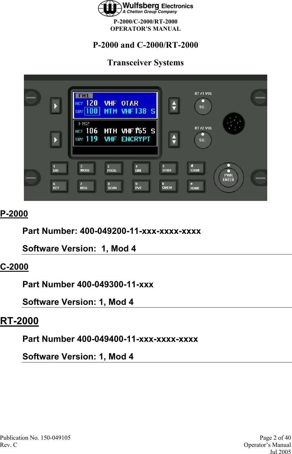
Wulfsberg Electronics Division 2000-VHFA VHF Transceiver User Manual 150 049105 C
Wulfsberg Electronics Division VHF Transceiver 150 049105 C
UserManual.wiki
>
Wulfsberg Electronics Division
>
2000-VHFA User Manual
>
Users Manual
Contents
1.
Users Manual
2.
Exposure Statement for User Manual
Users Manual
Navigation menu
Upload a User Manual
Namespaces
Wiki Guide
HTML
PDF
Info
Views
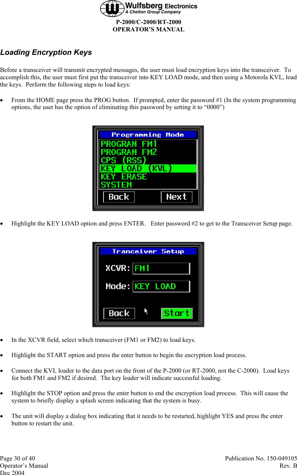
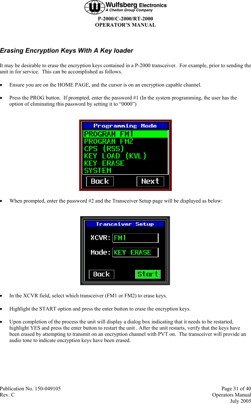
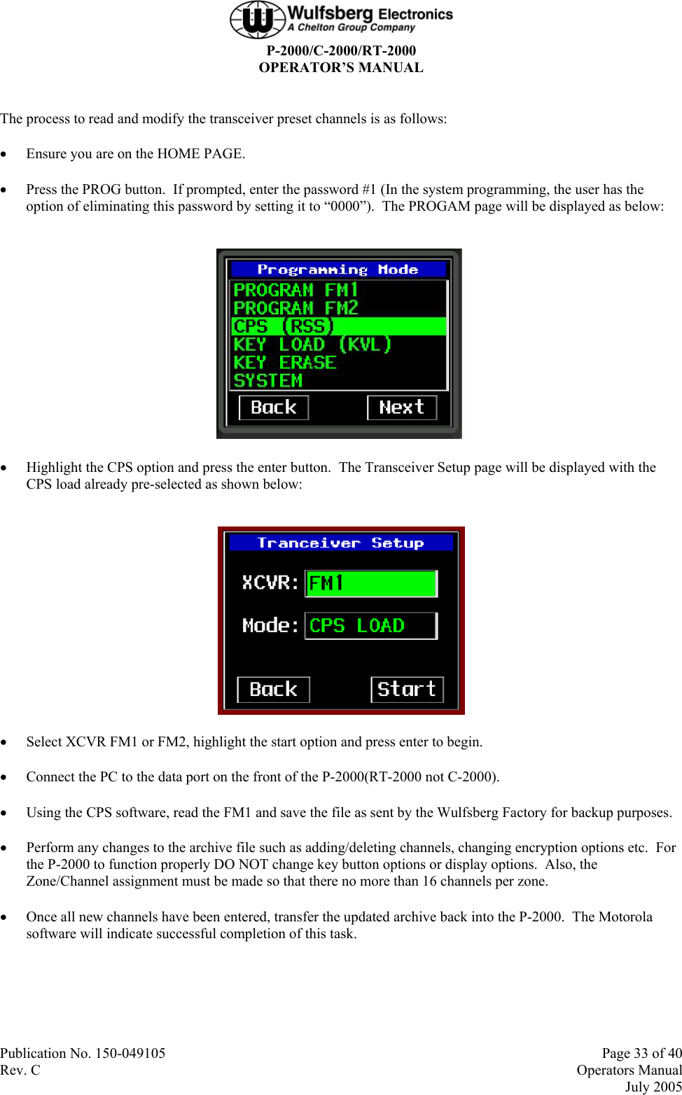
User Manual
Discussion / Help
Navigation