Wulfsberg Electronics Division NPX136D VHF Transceiver User Manual 813 0
Wulfsberg Electronics Division VHF Transceiver 813 0
Contents
- 1. User Manual
- 2. Installation Manual
User Manual

Page 1
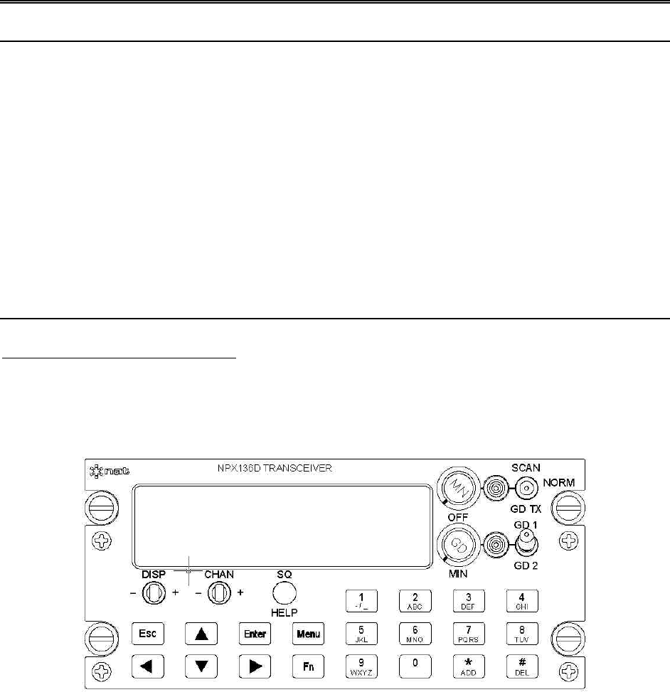
NPX136D-070 VHF P25 Panel Mount Transceiver
OPERATOR’S MANUAL
REV 0.01 April 5, 2004
Northern Airborne Technology Ltd.
#14-1925 Kirschner Road
Kelowna, BC, Canada.
V1Y 4N7
Telephone (250) 763-2232
Facsimile (250) 762-3374
Copyright 2004 by Northern Airborne Technology Ltd.
PRELIMINARY

Page 2
Table of Contents
Section Title Page
1.1 Introduction 3
1.2 Purpose of Equipment 3
1.3 Features 3
1.4 Operation 4
1.4.1 General 4
1.4.2 Power On 4
1.4.3 Controls 5
1.4.4 Normal Operating Mode 8
1.4.5 Menu Mode 10
1.4.6 Direct Function Operations 19
1.4.7 Scanning 19
1.5 Specifications 20
1.5.1 Radio Specifications 20
1.5.2 Main Receiver 21
1.5.3 Guard Receiver 21
1.5.4 Transmitter 21
1.5.5 Physical Specifications 22
1.5.6 Environmental Specifications 23
1.6 Unit Nomenclature 23
1.6.1 Options 23

Page 3
1.1 Introduction
This manual contains description and operation information on the NPX136D-070 Panel
Mount P25 VHF Transceiver, serial number 1001 and subsequent.
The NPX136D incorporates NAT’s proven user-friendly operating system with on-line
help, making it easy to program and use. The small size makes this radio ideal for
airframes where size and weight are a factor.
1.2 Purpose of Equipment
The NPX136D panel mount P25 VHF transceiver is a stand-alone radio designed for
the single mission user. It provides all the features needed to satisfy communications
within the VHF high band.
1.3 Features
The NPX136D covers a frequency range of 136.0000 to 173.9975 MHz in 2.5/6.25 kHz
increments. Each of the 256 available channels can operate in one of three modes:
wide band analog, narrow band analog or digital P25 Phase I.
A SCAN function allows scanning of selected channels. Transmit power of either 1 watt
or 10 watts is selectable from the front panel. Simplex and semi-duplex operations are
available. A guard receiver is standard with the -070 model.
Conveniently located beside the display are separate main volume, guard volume and
transmit select switches. Easily identified along the bottom of the front panel are
squelch test, channel up/down and display controls. The aircraft dimmer buss provides
control for the panel lighting.
Page 4
1.4 Operation
1.4.1 General
In addition to the general functions that are available on other FM radios, the NPX has
several features that extend its capability and make it easier to use. These features
include alphanumeric channel labeling, built-in operator help, scanning, optional guard
receiver, and numerous others.
For ease of use and operability, NAT uses a similar control layout and operating system
in the NPX138 series of radios as it does in its popular Tac/Com family of radio control
heads.
In addition to this manual, there is a help function built into the radio comprehensive
enough to address most operational questions.
1.4.2 Power On
1.4.2.1 Power-up Screen
Turn the NPX on by rotating the main (MN) volume control clockwise, away from the
‘Off’ detent position. The software revision number will briefly display, and, if enabled,
will be followed by a screen presenting an option for use of the on-line Help system.
To display a tutorial on the operation of the radio press the SQ/HELP button. To
advance through the tutorial press Enter after reading each screen. To exit the tutorial
press the ESC button.
NPX136D
S/W Ver: X.XX
Page 5
1.4.2.2 Initial Operating Display
If you decline ‘Help’ (by pressing the Esc button), the radio will display a summary of the
installed functions and current settings (this feature can be disabled for faster start-up).
The radio is then ready for normal operation, referred to as normal operating mode in
the remainder of this manual.
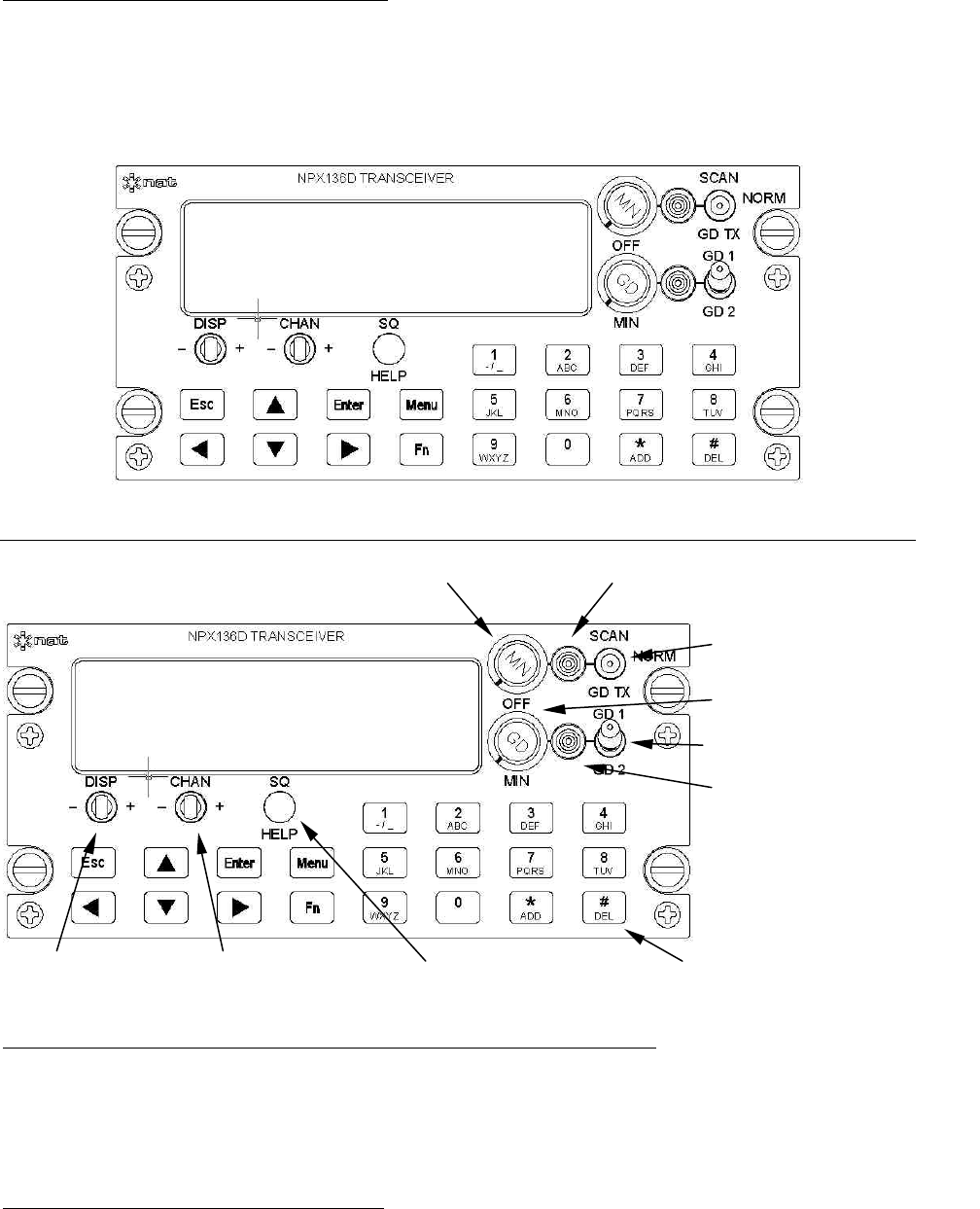
1.4.3 Controls
1.4.3.1 Main Receive Volume and Power On / Off Control
To turn on the radio rotate the MN knob clockwise past the OFF detent. To turn off the
radio rotate the MN knob counterclockwise past the OFF detent. To increase the
volume of the main receiver, turn this knob clockwise; to decrease the volume turn this
knob counterclockwise.
1.4.3.2 Guard Receive Volume
To increase the volume of the guard receiver, turn this knob clockwise; to decrease the
volume turn this knob counterclockwise. The guard receive audio cannot be turned off,
only set to a minimum level.
Main On/Off/Volume
Main RX/TX Annunciator
001=ABCDEFGHI W
S
C
R:173.975 067
Radio Status:
Tx Mode=Duplex
Scan Guard Transmit
Guard Volume
Guard RX/TX Annunciator
Guard Channel
Display Switch Channel Switch Squelch/Help Switch Keypad Push Buttons

Page 6
1.4.3.3 Main RX/TX Status Annunciator
The main RX/TX annunciator displays the RX (Receive) and the TX (Transmit) status of
the main transceiver. When transmitting the LED will light green. When receiving any
RF signal, the LED will light amber. When idle (not receiving or transmitting), the LED
will be dark. The colour coding used for these functions corresponds to standard aircraft
FM radio conventions. Note that this is the reverse of standard vehicular conventions
used with land mobile equipment.
The receive annunciator (amber) informs the operator that the channel is active with
radio traffic of some kind. A radio that is receiving may still not produce any audio if the
analog tones or digital squelch mode present on the receive signal do not match those
set in the radio.
1.4.3.4 Guard RX/TX Status Annunciator
The guard RX/TX annunciator displays the RX (Receive) and the TX (Transmit) status
of the guard channel. When the main transceiver is transmitting on the guard channel
(SCAN / GD TX switch in GD TX position) the LED will light green. When the guard
receiver is receiving any RF signal, the LED will light amber. When idle (not receiving or
transmitting), the LED will be dark.
1.4.3.5 Change channels on the main receiver
There are two different ways to select a channel on the main transceiver.
Step or scroll through the channels using the CHAN switch. To sequentially change
channels press the CHAN switch right ‘+’ to increment by one channel or left ‘-’ to
decrement by one channel. Holding the CHAN switch in either the left or right position
causes the radio to scroll through the channels. A remote channel switch may also be
connected to the rear connector of the NPX136D to provide the same function.
Jump directly to a specific channel by pressing the keypad buttons for the required
channel and then press the Enter button.
1.4.3.6 Scanning
Turn scan mode on by putting the SCAN/GD TX switch in the SCAN position. The lower
display will show "SCANNING XXX" where XXX is the current scan mode.
Turn scan mode off by putting the SCAN/GD TX switch in the centre position.
For details on scanning operation see section tbd.
1.4.3.7 Guard Transmit
To select the guard channel for the transmit frequency put the SCAN/GD TX switch in
the GD TX position, all radio transmissions will be on the transmit frequency
programmed in the selected guard channel. To use the main transceiver's channel for
the transmit frequency put the SCAN/NORM/GD TX switch in the NORM position.

Page 7
This function only applies to radios with the guard receiver option installed. If not, the
radio will display ‘GD NOT INSTALLED’ on the upper line when the switch is set to the
GD TX position.
1.4.3.8 Guard Channel Select
Select one of two guard channels, GD1 or GD2, with the GD1 / GD2 guard channel
select switch.
1.4.3.9 Squelch Pushbutton
To disable squelch, press and release the SQ button. The first time the button is
pressed the main receiver squelch is disabled. The second time the SQ button is
pressed the guard receiver squelch is disabled. Press the SQ button a third time to
return to normal squelch operation.
When the main receiver has squelch disabled the lower display will show MN
SQUELCH DSBL or GD SQUELCH DSBL when on an analog channel; and MAIN
MONITOR or GUARD MONITOR when on a digital channel. Note that when the
squelch is disabled on a digital channel that is not receiving a digital transmission no
audio will be heard.
1.4.3.10 Using Menus
Pressing the Menu button displays the menus for the radio settings, channel edit, zone
edit, scan edit and maintenance mode. Press the Menu button to advance to the next
menu screen. Press the Enter button to display the sub-menus or editable fields under a
menu. Then press the Menu button again to advance to the next sub-menu or next
editable field. Press the Esc button to exit a menu. When any settings are changed the
operator is prompted to "Save Changes?" press the Enter button to save the changes,
press the Esc button to discard changes.
1.4.3.11 Change Radio Settings
The display brightness, transmit power for all channels, transmit mode for all channels,
analog tones on/off for all channels and digital squelch mode for all channels, as well as
the power up channel, and display options may changed from the Settings Menu. For
details see section 1.4.5.1.
1.4.3.12 Change Channel, Zone or Scan Settings
The channel settings (for both main and guard channels) the zone settings and scan
settings are accessed from the Edit Menu. For details see section 1.4.5.3.
1.4.3.13 Maintenance Menu
More detailed settings that are not normally used, or that should be changed by a
knowledgeable user, are accessed from the Maintenance Menu. For details see section
1.4.5.9.
1.4.3.14 Accessing Help Screens
Help screens are displayed when in any menu mode (but not normal operating mode.)
Page 8
To read the help for any menu item press the help (SQ / HELP) button. Use the arrow
buttons to change the view of the help text and press the ESC button to return to the
menu or field that the help was from.
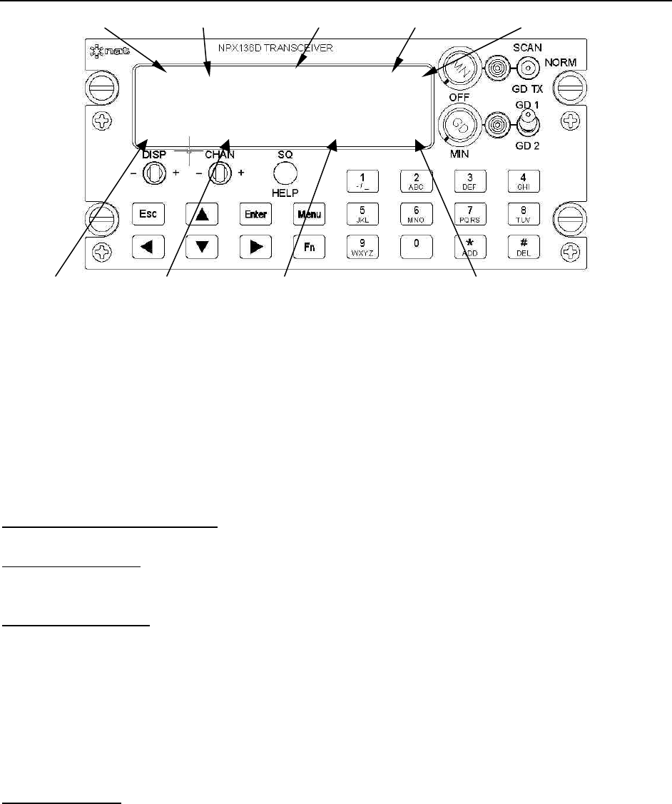
1.4.4 Normal Operating Mode
The figure above shows a typical radio display in normal operating mode. The upper
row of the display contains the channel number, channel name and various flags. The
channel's tone/squelch flag shows the state of analog tones or digital squelch mode.
The channel's modulation type flag shows the modulation mode. The scan flag shows if
the current channel is in the scan list or is a priority scan channel.
The lower row of the display contains information related to specific radio functions. The
display can shows the current zone (if zones are enabled) or the receive settings or the
transmit settings for the current channel.
1.4.4.1 Display Details
Channel Number: A reference for the current channel. Channel numbers are 001 – 256
and GD1, GD2.
Tone/Squelch Flag:
Analog Channels: Blank for analog tones off. Dash "–" for transmit only. Equal Sign "="
for analog tones on. The analog tone is transmitted and the received tone (CTCSS or
CDCSS tone) must match the channel's receive tone in order to hear received audio.
Digital Channels: "M" for monitor mode where all audio on a digital channel is heard. "N"
for normal mode where the received network access code (NAC) must match the
channel's receive NAC for audio to be heard. "S" for select mode where the received
talk group ID must match the channel's receive talk group ID for audio to be heard.
Channel Name: Alphanumeric name for the channel consisting of nine characters.
Channel Number Tone/Squelch Flag Channel Name Modulation Type Scan Flag
001=ABCDEFGHI W
S
C
R:173.997 067 TG
Display Type Frequency Tone/Squelch Number Talk Group Flag

Page 9
Modulation Type: The modulation type for the current channel. "W" for wideband
analog. "N" for narrow band analog. "D" for P25 Phase I digital.
Scan Flags: " SC " for current channel in scan list. " P1 " or " P2 " for current channel in
priority scan.
Display Type: "Z:" for zone display, only shown if zones are turned on. "R:" for receive
display. "T" for transmit display. "S" for simplex display. "RTG" for receive talk group
and TTG for transmit talk group.
Zone display: shows the zone number and zone name for the current zone. The
zone display is only displayed if turned on from the zone menu.
Receive Display: Shows the receive frequency in MHz to three decimal places,
and receive analog tone or receive network access code or dashed lines if no
tone is selected or squelch mode is set to monitor, and " TG " if the channel has a
receive talk group ID set.
Transmit Display: Shows the transmit frequency in MHz to three decimal places,
and transmit analog tone or transmit network access code or dashed lines if no
analog tone or digital squelch is set, and " LO " or " HI " for the radio's transmit
power setting.
Simplex Display: Shows the receive and transmit frequency in MHz to three
decimal places, and receive and transmit analog tone or receive network access
code or dashed lines if no analog tone or digital squelch is set, and " LO " or " HI "
for the radio's transmit power setting.
Receive Talk Group ID: Shows the receive talk group ID for the channel. The
receive talk group ID is only displayed if talk groups are turned on from the
display menu.
Transmit Talk Group ID : Shows the transmit talk group ID for the channel. The
transmit talk group ID is only displayed if talk groups are turned on from the
display menu.
Page 10
1.4.5 Menu Mode
1.4.5.1 Settings Menu
The settings menu allows changing of general radio settings.
a) Brightness
The display is dimmable in 32 steps. This setting is stored in non-volatile
memory.
When the external lights inputs is above tbd % of nominal level, the display is
dimmed by tbd steps
When the external lights input is adjusted from tbd to tbd % of nominal
levelthe display is dimmed from tbd to tbd.
The LED display illumination changes as the brightness level is adjusted from
the menu as follows.
b) Transmit Power
The transmit power level for all channels can be changed from Lo, 1 Watt or
Hi, 10 Watts or may be set to Per Chan where the Hi/Lo power setting from
the channel controls the transmit power level.
c) Transmit Mode
There are two modes possible: DUPLEX (repeater) operation, and SIMPLEX
(direct) operation. Duplex means that the radio uses both the RX and TX
frequencies programmed into the selected channel. Simplex means that the
radio uses the RX frequency and tone or digital squelch programmed into the
selected channel for both RX and TX purposes.
d) Squelch Mode, Analog Tones and Digital Squelch
CTCSS and DCS tones are selectable to ON, OFF, or TX ONLY.
Settings Menu
Brightness: 32
Page 11
Network Access Codes (NAC), Talk group IDs and Unit IDs operation may be
selected to Monitor, Normal, Select.
Table of digital squelch used based on channel and global settings.
Settings Menu: Dgtl Sqlch Channel Setting:
Dgtl Sqlch
MONitor NORmal SELect
MONitor
MON MON MON
NORmal
MON RxNAC RxNAC
SELect
MON RxNAC RxTGID
e) Power Up Channel
The channel that the radio tunes to after power up may be set as the power
down channel (PrDn) or as a specific channel number.
f) Encryption Mode
Encryption can be turned on or off. Only displayed if encryption is available.
g) Display Settings
A sub menu for the display settings can be accessed to change the way
information is displayed. See section 1.4.5.2.
1.4.5.2 Display Settings
a) Tones Display
CTCSS tones may be displayed as one of two methods: Motorola Code, or
Frequency.
b) NAC Display
For digital channels only, the network access code (NAC) may be displayed as a
decimal number from 0000–4096 or as a hexidecimal number 000h-FFFh.
c) TGID Display
For digital channels only, the talk group ID for Rx and Tx is displayed after the
frequency when the DISP switch is toggled.
d) Power Up Help
Display of help screens at power up can be turned on and off from this menu.
e) Power Up Status
Display of status screens at power up can be turned on and off from this menu.
f) Channel Number Mode
The channel number may be numeric 001-256 or may include alphanumeric
characters so that channels like M16 can be entered.

Page 12
1.4.5.3 Edit Menu
The edit menu allows access to the menus for editing channels, editing guard channels,
editing scan lists, editing zones. See sections 1.4.5.4 – 1.4.5.7 for details.
1.4.5.4 Edit Channel Menu
The Edit Channel Menu is a sub-menu of the Edit Menu.
Allows editing of the parameters of a channel that have not been locked out from the
serial load program. Select a different channel using the CHAN + / – switch to scroll to
the required channel.
The Main receiver continues to operate with the original settings until the field is saved /
menu is saved. The transmitter is locked out from operation when in channel edit.
If channel is locked the lower display will show "LOCKED!" Press Enter to review the
channel data.
a) Channel receive/transmit frequency:
RxFreq, TxFreq: 136.00000 – 173.99750 MHz
in 0.0025 or 0.00625 MHz increments. After entering a new receive
frequency the transmit frequency is set to the new receive frequency.
Only the numbers shown in bold are displayed or may be edited.
Numbers shown in italics are not displayed
Table of allowed frequencies:
1xx.x0000 1xx.x3500 1xx.x7000
1xx.x0250 1xx.x3750 1xx.x7250
1xx.x0500 1xx.x4000 1xx.x7500
1xx.x0625 1xx.x4250 1xx.x7750
1xx.x0750 1xx.x4375 1xx.x8000
1xx.x1000 1xx.x4500 1xx.x8125
1xx.x1250 1xx.x4750 1xx.x8250
1xx.x1500 1xx.x5000 1xx.x8500
1xx.x1750 1xx.x5250 1xx.x8750
1xx.x1875 1xx.x5500 1xx.x9000
1xx.x2000 1xx.x5625 1xx.x9250
1xx.x2250 1xx.x5750 1xx.x9375
1xx.x2500 1xx.x6000 1xx.x9500
1xx.x2750 1xx.x6250 1xx.x9750
1xx.x3000 1xx.x6500
1xx.x3125 1xx.x6750
1xx.x3250 1xx.x6875
The receive or transmit frequency may be any number between 136.00000
and 173.99750 MHz that is divisible by 2.5 or 6.25 kHz. ***.*** is displayed if
the frequency is not valid.
Page 13
b) Channel Name
Name:xxxxxxxxx
Allowed characters: 0–9, A–Z, a–z ,-/_
The channel name can be any 9 alphanumeric characters.
The number and letters available are on the 0-9 buttons. The character to be
entered is flashing. Press the button until the required character is displayed
at the flashing position. Press a different button to advance to the next
character. If the next character required is on the same button press the right
arrow button to advance to the next character. To change previous characters
press the left arrow to move to the previous positions.
c) Modulation Type:
The channel modulation type may be set to analog wide band analog narrow
band or digital.
d) Channel Scan List
Scan List: Yes/No
If the channel is to be checked for carrier when list scanning then set the scan
list to yes.
e) ChannelTransmit Power
Tx Power: Hi/Lo
Channel power is only used when the global transmit power setting is Per
Chan. Otherwise the transmit power is from the global setting
f) Zone
Zone:ALL/01–16
Only displayed if zones are turned on from zone menu.
The channel zone may be set to one zone number or to All. A channel may
belong to only one zone or to all zones.
g) Channel Number: 000–999 or AAA–ZZZ
Displayed only when in master edit mode
The channel number is editable only when in Master Edit Mode.
h) Receive Subaudible Tone Type
Displayed for analog modulation mode only
Rx Tn Typ:None/Ctcss/Dcs
i) Receive Subaudible Tone
Displayed only if receive subaudible tone type set to Ctcss or Dcs.
Rx Tone: {Ctcss frequency/code or Dcs Code}
j) Transmit Subaudible Tone Type
Displayed for analog modulation mode only
Tx Tn Typ:None/Ctcss/Dcs

Page 14
k) Transmit Subaudible Tone
Display only if receive subaudible tone type set to Ctcss or Dcs.
Tx Tone: {Ctcss frequency/code or Dcs Code}
l) Receive Digital Squelch
Displayed only if modulation type is set to digital.
Dgtl Sqlch: Sel/Norm/Mon
Where Sel is for Select Mode, Norm is for Normal Mode and Mon is for
Monitor Mode.
m) Receive Network Access Code
Displayed only if Receive Digital Squelch set to normal or select.
Rx NAC: 000h – FFFh
n) Receive Talk Group ID
Display only if Receive Digital Squelch set to select.
Rx TGID: 0000h – FFFFh
o) Transmit Network Access Code
Displayed only if modulation type is set to digital.
Tx NAC: 000h – FFFh
p) Transmit Talk Group ID
Displayed only if modulation type is set to digital.
Tx TGID:0000h – FFFFh
q) Encryption Key
Only displayed when encryption is enabled
Encr Key: Off/01 – 16.
1.4.5.5 Edit Guard Channel Menu
The Edit Guard Menu is a sub-menu of the Edit Menu.
Allows editing and review of the guard channels' parameters. The channel being edited
can be changed at any time using the GD1 / GD2 switch. Guard Channels are always
locked, and can only be edited if the master edit mode is on.
The guard receiver continues to operate with the original settings until the field is saved
/ menu is saved.
All fields are the same as for the main channels.
1.4.5.6 Edit Zone Menu
The Edit Zone Menu is a sub-menu of the Edit Menu.

Page 15
There are 16 zones. A channel may belong to one zone or all zones. When a zone is
selected only the channels assigned to that zone and to all zones are displayed.
a) Turn Zones on and off.
Use Zones: Off / On
Allow zones to be turned on or off
b) Edit Zone's Name
Name:XXXXXXXXX
Change the name of the current zone. Use the up and down arrow buttons to
select a different zone.
c) Zone Review
Zone XX [List]:
ZXX Zone Name
Review the channels assigned to each zone.
Use the Channel switch to display the next or previous channel. Use the up and
down arrow buttons to select different zones. Use the DEL button to remove a
channel from a zone. Use the ADD button to enter channel add mode and then
scroll to the required channel and press ADD again.
1.4.5.7 Scan Edit Menu
The Edit Scan Menu is a sub-menu of the Edit Menu.
a) Scan Mode
Scan Mode= List, Priority, List+Priority
b) Priority 1 Channel
Edit Scan:
Pri1: xxx {001 - 256}
Enter the number of the channel required to be the Priority 1 Channel.
c) Priority 2 Channel
Edit Scan:
Pri2: xxx {001 – 256}
Pri 1 Help:
Enter the number of the channel required to be the Priority 2 Channel.
d) Scan List Review/Edit
Edit Scan:
Review Scan List
Review Scan List
001:Forestry
Use the ADD and DEL keys to add or delete channels from the scan list.
In scan edit the scan list, priority channels, and scan mode may be changed.

Page 16
e) Home Channel
Scan Menu:
Home Chan:xxx { 001-999}
Enter the number of the channel required to be the Home Channel.
1.4.5.8 Call Menu:
The call menu is accessed from the Fn (Call ) button.
Press the Fn (Call) button to enter the Call Menu. Press the Menu button to cycle
through the Recent Call list and the Recall Memory List. Press the Enter button to
access the Manual DTMF menu.
a) Manual DTMF
Press Esc to clear the DTMF sequence.
Enter a series of up to tbd digits 0–9,*,# and press Enter.
Use the right and left arrows to move the flashing cursor around the DTMF
sequence. Spaces are transmitted as a pause. Use the down arrow to change a
number to a space. The transmitter is activated and the DTMF sequence is
transmitted. Return to normal operating mode after 10 tbd. seconds.
b) DTMF Memory
Use the ADD button to add to access save to memory menu.
DTMF:XX
BLANK / <display old number>
c) Recent Calls
When the current channel modulation type is analogue this option is displayed.
Select the DTMF sequence from a list of up to 10 previously transmitted
sequences and press Enter.
The transmitter is activated and the DTMF sequence is transmitted. Return to
normal operating mode after 10 tbd. seconds. Use the ADD button to store to
memory.
Redial DTMF
1:12345678901234

Page 17
1.4.5.9 Maintenance Menu:
a) Encryption: Erase Keys
All encryption keys are zero-ized.
Maint. Menu
Erase Encr Keys?
b) Master Edit Mode
Enter master edit password to be allowed to edit locked channels.
Maint. Menu
Mstr Edit Mode?
Mstr Edit Mode
Password:NAT
Mstr Edit Help:
Enter the master edit password to edit locked channels.
Return to normal operating mode once password is entered. Master Edit
Mode is disabled when power is turned off. Every tbd seconds after no switch
presses a banner notice is displayed that master edit mode is on. Press any
key to turn off notice.
Notice:
>Master Edit Mode is on. To turn off cycle power off and
on.
c) Configuration Menu
Enter the configuration password (IAC) to edit the configuration information.
Maint. Menu
Config Menu?
Config Menu
Password:XXXIAC
Config Help:
Enter the Configuration password to allow editing of the
configuration settings in the maintenance menu
d) User ID
Config Menu
User ID:XXXXXXXX
e) Test Menu
Refer to the NPX136D Alignment Procedure for instructions on using the test
menu.
Page 18
Only displayed if IAC password entered:
1. Switch Test
The lower display shows the number of the switch being operated and the
action or value of the switch. Press and hold the Esc button for 3 seconds to
exit the test.
F/P Switch Test
<Switch Number><Switch Action or Value>
2. Display Test.
The display's characters are cycled between three states: All odd pixels on,
all even pixels on, and all characters displayed as the pound sign "#".
3. Bit Error Rate Test
The main and guard receivers are put into BER mode and the bit error rate
information is sent out the serial port.
f) Mute Unmute Volume Level Menu
Only displayed if IAC password entered:
Refer to the NPX136D Alignment Procedure for instructions on using the
Volume Level fields.
Mn Unmute: 2 to16.
Mn Muted: 1 to (Main Unmute minus1)
Gd Unmutes: 2 to16.
Gd Muted: 1 to (Guard Unmutes minus 1)
Config Menu
Gd Vol Min: XX
Config Menu
Sidetone: XX
g) Transmit Time-out Timer
Only displayed if in Config Menu.
The transmit time-out timer sets the duration, in seconds, for which the
transmitter is allowed to transmit.
Config. Menu
Tx Time-out: XX {30,60,...,300, default 60 s}
h) Number of Channels
Only displayed if in Config Menu.
The number of channels in the main transceiver may be changed. from 001 –
256.

Page 19
i) Serial Load or Data Transfer Menu
Allows copying of channel, tone, talk group, and individual data from the
source transceiver to the destination transceiver over the RS-232 data cable
connected to a PC or another NPX136D.
Channel Data (Serial Load)
The transceiver must allow channel parameters to be downloaded or
uploaded with another NPX136D transceiver with a FC4x-xxx cable or a serial
load PC program (NUDP-NPX136D) through the serial port on the J1 Power
Audio Connector (Through the FC42-001 serial load cable?) or
Maint. Menu:
Data Xfer
Data Xfer:
Mode: ddddddddd {Download/Upload}
Data Xfer:
Waiting... / Not Connected / Error / Xfer XXX / Done
1.4.6 Direct Function Operations
This section has not yet been written
1.4.7 Scanning
This section has not yet been written

Page 20
1.5 Specifications
1.5.1 Radio Specifications
Input power 28 Vdc nominal
Current consumption tbd A receive/ tbd A transmit (typical)
tbd A receive/ tbd A transmit (max.)
Panel lighting 28 Vdc, 14 Vdc or 5 Vdc dependent on model.
Lights Current tbd (max.)
Frequency Range: 136.000 – 173.9975 MHz
Operating Modes: Project 25 and conventional Analog Simplex or Semi-
Duplex
Channels: 256 max. Plus GD1 and GD2
Zones: 16 max.
Sub-audible signaling: CTCSS - 42 tones from 67.0 to 254.8 Hz
CDCSS - 83 data patterns
Remote Interface: 1. RS232C Data, to PC for Channel Loading and
Firmware Loading
2. Controller Area Network (CAN) Data to other CAN
enabled equipment (Optional)
3. tbd. P25 Data Peripherial Interface. (Optional)
4. Keyload Data to KVL Keyloader (Optional)
RF Input/Output Impedance: 50 ohms
Voice Digital Mode: IMBE 4.4 kb
Frame Re-sync Interval: 180 ms
Error Correction Algorithms: RS / Golay / Hamming
Channel Increments: 2.5 / 6.25 kHz
Channel Spacing: 12.5 / 25 kHz
Scan Capability: 16 channels max. 1 home, 2 priority, 13 list.
Scan Rate tbd channels per second.
Encryption: SBCF Analogue DES (Optional)
Encryption Keys: 16 (Optional)
APCO P25 OFB Encryption: Option available by transceiver module software
upgrade.
OTAR (Over the air re-keying) Option available by transceiver module software
upgrade.

Page 21
1.5.2 Main Receiver
Reference Sensitivity (12 dB SINAD): = -113 dBm
Adjacent Channel Rejection: = 70 dB (25 kHz BW) / = 60 dB (12.5 kHz BW)
Spurious Response Rejection: = 70 dB
Intermodulation Rejection: = 70 dB
Audio Output Power: 100 mW (600 ohms) rated
Audio Frequency Response: 300 – 500 Hz, 0 dB/Octave
500 – 2500 Hz,
(EIA Std. -6dB(+1/-3dB)/octave de-emphasis)
2500 – 3000 Hz, -12 dB/octave
Audio Distortion: 3% typ. (10% max.)
Conducted Spurious Emissions: = -57 dBm
FM Hum and Noise = 34 dB (NB), = 40 dB (WB),
= tbd dB muted
Receiver Attack Time = 150 ms
Receiver Closing Time = 250 ms
Audio Mute Level 12 ± 1 dB SINAD
Audio Unmute Level 15 ± 1 dB SINAD
1.5.3 Guard Receiver
All specifications are identical to the main receiver.
Audio Output Power, minimum: 10 mW (adjustable)
Main and Guard cannot be 455 kHz from each other due to 2nd IF interference
1.5.4 Transmitter
Carrier Output Power: 1 or 10 W ±1 dB
Time-out Timer: 30-300 s (Factory Set to 60 s)
Duty Cycle: 20% (1 min Tx, 4 min Rx.)
VSWR: 20:1 (30 sec duration - undamaged)
Transmitter Stability into VSWR: (3:1): Spurious Output = -13 dBm
Rated Deviation: ± 5.0 kHz (25 kHz BW)
± 2.5 kHz (12.5 kHz BW)
Carrier Frequency Stability: ±2.5 ppm
Conducted Spurious Emissions: = -20 dBm
Adjacent Channel Power: = -70 dBc (25 kHz BW)

Page 22
= -60 dBc (12.5 kHz BW)
FM Hum and Noise: 40 dB (25 kHz BW)
34 dB (12.5 kHz BW)
Microphone Input Impedance: 150 Ω ±20 %
Audio Frequency Response: 300 – 3000 Hz
(EIA Std. 6dB(+1/-3dB) /octave pre-emphasis)
Audio Distortion: 3% typ. (10% max.)
Audio Input Sensitivity: 100 mV rms (60% of rated deviation)
Sidetone Audio Level: 25 mW (Adjustable)
Transmitter CTCSS Tone Deviation: 475 +/- 125 Hz (12.5 kHz BW)
750 +/- 250 Hz (25 kHz BW)
Carrier Attack Time = 100 ms.
1.5.5 Physical Specifications
Total Length 8.90"
Depth 7.02" (behind panel) not including connectors.
Width 5.75", 4.97 behind panel
Height 2.63"
1.5.5.1 Faceplate
Black with white text. Font Style = Arial. Size = 0.085".
Push button colour is gray with white text. Font Style = Arial. Size = 0.065".
Blue/White Incandescent backlighting
+28 Vdc Standard
+14 Vdc Optional
+5 Vdc Optional
Night Vision Goggle useable +28 Vdc Optional
1.5.5.2 Weight
4 lbs. (max.)
Qual Run S/N 1001–1005: 2.9 lbs.
1.5.5.3 Mounting
Four standard Dzus-rail fasteners
1.5.5.4 Connectors

Page 23
J1: Power Primary Connector
25 pin male D-subminiature, locking hardware JVL type.
J2: RF Connector BNC female RF connector
J3: Data Connector15 pin male D-subminiature, , locking hardwareJVL type.
1.5.5.5 Install Kit
NPX136D-IKC/S (Includes 25 pin and BNC not 15 pin)
1.5.6 Environmental Specifications
Temperature -30 C to +60 C
Altitude 50,000 feet
Humidity 95 %
Shock 12g (any axis)
DO-160C Env. Cat. [(B4)(D1)]BAA[(SBM)(UF)]XXXXXXABABA[UUX]MXXXX
1.6 Unit Nomenclature
NPX136D radios are identified as follows:
NPX136D – 070
1.6.1 Options
1.6.1.1 Lighting Power
NPX136D - 070
0 = 28 Vdc Lights
1 = 14 Vdc Lights
2 = NVG usable option
5 = 5 Vdc Lights
1.6.1.2 Special Options
NPX136D - 070
7 = Synthesized Guard
x = OFB Encryption
y = OTAR Re-Keying