Wulfsberg Electronics Division NTX403 NTX403 UHF FM Transceiver User Manual Section 2 0 Installation

Wulfsberg Electronics Division NTX403 UHF FM Transceiver Section 2 0 Installation

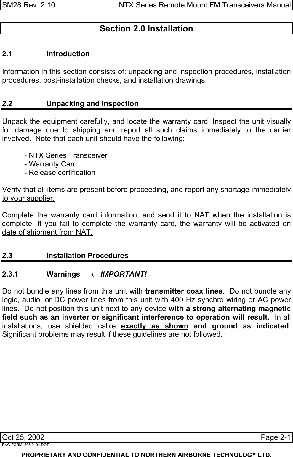
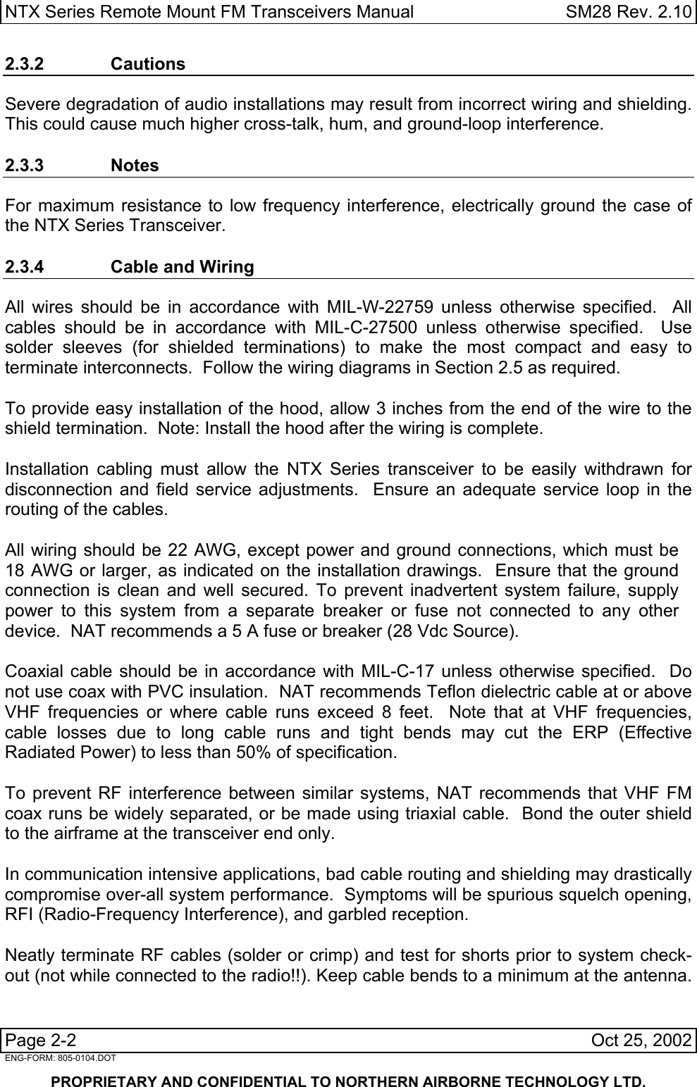
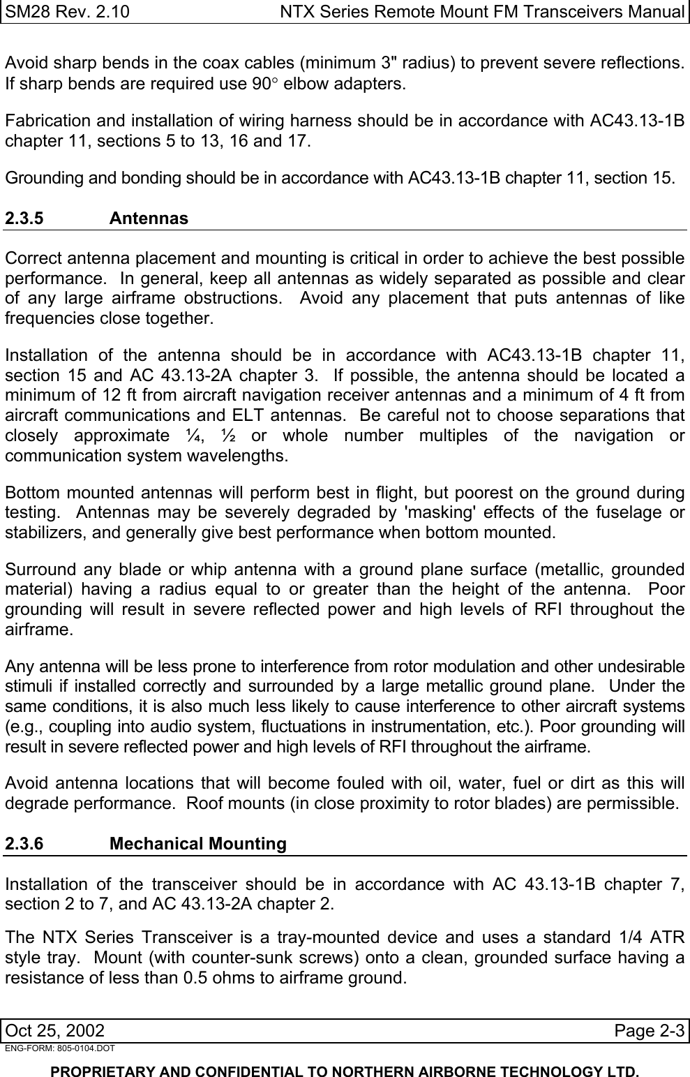
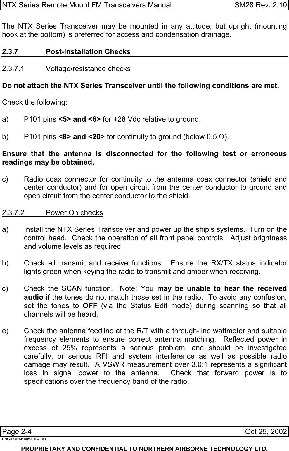
Installation instructions

SM28 Rev. 2.10  NTX Series Remote Mount FM Transceivers Manual  Section 2.0 Installation 2.1 Introduction Information in this section consists of: unpacking and inspection procedures, installation procedures, post-installation checks, and installation drawings.  2.2  Unpacking and Inspection Unpack the equipment carefully, and locate the warranty card. Inspect the unit visually for damage due to shipping and report all such claims immediately to the carrier involved.  Note that each unit should have the following:    - NTX Series Transceiver   - Warranty Card   - Release certification  Verify that all items are present before proceeding, and report any shortage immediately to your supplier.  Complete the warranty card information, and send it to NAT when the installation is complete. If you fail to complete the warranty card, the warranty will be activated on date of shipment from NAT. 2.3 Installation Procedures 2.3.1 Warnings ← IMPORTANT! Do not bundle any lines from this unit with transmitter coax lines.  Do not bundle any logic, audio, or DC power lines from this unit with 400 Hz synchro wiring or AC power lines.  Do not position this unit next to any device with a strong alternating magnetic field such as an inverter or significant interference to operation will result.  In all installations, use shielded cable exactly as shown and ground as indicated.  Significant problems may result if these guidelines are not followed. Oct 25, 2002  Page 2-1   ENG-FORM: 805-0104.DOT       PROPRIETARY AND CONFIDENTIAL TO NORTHERN AIRBORNE TECHNOLOGY LTD.
NTX Series Remote Mount FM Transceivers Manual   SM28 Rev. 2.10  2.3.2 Cautions Severe degradation of audio installations may result from incorrect wiring and shielding.  This could cause much higher cross-talk, hum, and ground-loop interference.    2.3.3 Notes For maximum resistance to low frequency interference, electrically ground the case of the NTX Series Transceiver.  2.3.4  Cable and Wiring All wires should be in accordance with MIL-W-22759 unless otherwise specified.  All cables should be in accordance with MIL-C-27500 unless otherwise specified.  Use solder sleeves (for shielded terminations) to make the most compact and easy to terminate interconnects.  Follow the wiring diagrams in Section 2.5 as required.  To provide easy installation of the hood, allow 3 inches from the end of the wire to the shield termination.  Note: Install the hood after the wiring is complete.  Installation cabling must allow the NTX Series transceiver to be easily withdrawn for disconnection and field service adjustments.  Ensure an adequate service loop in the routing of the cables.  All wiring should be 22 AWG, except power and ground connections, which must be 18 AWG or larger, as indicated on the installation drawings.  Ensure that the ground connection is clean and well secured. To prevent inadvertent system failure, supply power to this system from a separate breaker or fuse not connected to any other device.  NAT recommends a 5 A fuse or breaker (28 Vdc Source).  Coaxial cable should be in accordance with MIL-C-17 unless otherwise specified.  Do not use coax with PVC insulation.  NAT recommends Teflon dielectric cable at or above VHF frequencies or where cable runs exceed 8 feet.  Note that at VHF frequencies, cable losses due to long cable runs and tight bends may cut the ERP (Effective Radiated Power) to less than 50% of specification.  To prevent RF interference between similar systems, NAT recommends that VHF FM coax runs be widely separated, or be made using triaxial cable.  Bond the outer shield to the airframe at the transceiver end only.    In communication intensive applications, bad cable routing and shielding may drastically compromise over-all system performance.  Symptoms will be spurious squelch opening, RFI (Radio-Frequency Interference), and garbled reception.  Neatly terminate RF cables (solder or crimp) and test for shorts prior to system check-out (not while connected to the radio!!). Keep cable bends to a minimum at the antenna.  Page 2-2    Oct 25, 2002 ENG-FORM: 805-0104.DOT      PROPRIETARY AND CONFIDENTIAL TO NORTHERN AIRBORNE TECHNOLOGY LTD.
SM28 Rev. 2.10  NTX Series Remote Mount FM Transceivers Manual  Avoid sharp bends in the coax cables (minimum 3" radius) to prevent severe reflections.  If sharp bends are required use 90° elbow adapters.  Fabrication and installation of wiring harness should be in accordance with AC43.13-1B chapter 11, sections 5 to 13, 16 and 17.  Grounding and bonding should be in accordance with AC43.13-1B chapter 11, section 15.  2.3.5 Antennas Correct antenna placement and mounting is critical in order to achieve the best possible performance.  In general, keep all antennas as widely separated as possible and clear of any large airframe obstructions.  Avoid any placement that puts antennas of like frequencies close together.   Installation of the antenna should be in accordance with AC43.13-1B chapter 11, section 15 and AC 43.13-2A chapter 3.  If possible, the antenna should be located a minimum of 12 ft from aircraft navigation receiver antennas and a minimum of 4 ft from aircraft communications and ELT antennas.  Be careful not to choose separations that closely approximate ¼, ½ or whole number multiples of the navigation or communication system wavelengths.  Bottom mounted antennas will perform best in flight, but poorest on the ground during testing.  Antennas may be severely degraded by 'masking' effects of the fuselage or stabilizers, and generally give best performance when bottom mounted.  Surround any blade or whip antenna with a ground plane surface (metallic, grounded material) having a radius equal to or greater than the height of the antenna.  Poor grounding will result in severe reflected power and high levels of RFI throughout the airframe.  Any antenna will be less prone to interference from rotor modulation and other undesirable stimuli if installed correctly and surrounded by a large metallic ground plane.  Under the same conditions, it is also much less likely to cause interference to other aircraft systems (e.g., coupling into audio system, fluctuations in instrumentation, etc.). Poor grounding will result in severe reflected power and high levels of RFI throughout the airframe.  Avoid antenna locations that will become fouled with oil, water, fuel or dirt as this will degrade performance.  Roof mounts (in close proximity to rotor blades) are permissible.     2.3.6 Mechanical Mounting Installation of the transceiver should be in accordance with AC 43.13-1B chapter 7, section 2 to 7, and AC 43.13-2A chapter 2.  The NTX Series Transceiver is a tray-mounted device and uses a standard 1/4 ATR style tray.  Mount (with counter-sunk screws) onto a clean, grounded surface having a resistance of less than 0.5 ohms to airframe ground. Oct 25, 2002  Page 2-3   ENG-FORM: 805-0104.DOT       PROPRIETARY AND CONFIDENTIAL TO NORTHERN AIRBORNE TECHNOLOGY LTD.
NTX Series Remote Mount FM Transceivers Manual   SM28 Rev. 2.10  The NTX Series Transceiver may be mounted in any attitude, but upright (mounting hook at the bottom) is preferred for access and condensation drainage.  2.3.7 Post-Installation Checks 2.3.7.1 Voltage/resistance checks  Do not attach the NTX Series Transceiver until the following conditions are met.  Check the following:  a) P101 pins <5> and <6> for +28 Vdc relative to ground.  b) P101 pins <8> and <20> for continuity to ground (below 0.5 Ω).     Ensure that the antenna is disconnected for the following test or erroneous readings may be obtained.  c)  Radio coax connector for continuity to the antenna coax connector (shield and center conductor) and for open circuit from the center conductor to ground and open circuit from the center conductor to the shield.  2.3.7.2  Power On checks  a)  Install the NTX Series Transceiver and power up the ship’s systems.  Turn on the control head.  Check the operation of all front panel controls.  Adjust brightness and volume levels as required.  b)  Check all transmit and receive functions.  Ensure the RX/TX status indicator lights green when keying the radio to transmit and amber when receiving.  c)  Check the SCAN function.  Note: You may be unable to hear the received audio if the tones do not match those set in the radio.  To avoid any confusion, set the tones to OFF (via the Status Edit mode) during scanning so that all channels will be heard.  e)  Check the antenna feedline at the R/T with a through-line wattmeter and suitable frequency elements to ensure correct antenna matching.  Reflected power in excess of 25% represents a serious problem, and should be investigated carefully, or serious RFI and system interference as well as possible radio damage may result.  A VSWR measurement over 3.0:1 represents a significant loss in signal power to the antenna.  Check that forward power is to specifications over the frequency band of the radio. Page 2-4    Oct 25, 2002 ENG-FORM: 805-0104.DOT      PROPRIETARY AND CONFIDENTIAL TO NORTHERN AIRBORNE TECHNOLOGY LTD.
SM28 Rev. 2.10  NTX Series Remote Mount FM Transceivers Manual  2.3.8  Post-Installation EMI Test The purpose of this test is to identify any interference that the NTX138 may cause with existing aircraft systems.  The NTX138 should be tested in accordance with the Installation Approval Test Procedure (see section 2.5) and the test results documented on the record sheets.   2.4 Continued Airworthiness Maintenance of the NTX138 is ‘on condition’ only.  Periodic maintenance of these products is not required.   2.5 Installation Drawings Note:   The NTX138 drawings listed below are valid for the installation of  all NTX Series models.  DRAWING REV. DESCRIPTION  TYPE  NTX138\403-0  1.22  Remote Mount Radio  Interconnect NTX138\405-0  1.00  Remote Mount Radio  Connector Map NTX138\922-0  1.02  Remote Mount Radio  Mechanical NTX-VT1\922-0  1.00  Vertical Mount Tray  Mechanical   NTX138\634-0  1.00  Post-Installation EMI Test  Installation Approval Test Procedure   Section 2.0 ends after these Drawings  Oct 25, 2002  Page 2-5   ENG-FORM: 805-0104.DOT       PROPRIETARY AND CONFIDENTIAL TO NORTHERN AIRBORNE TECHNOLOGY LTD.

Navigation menu