Wulfsberg Electronics Division RT-5000P-07 29.7 to 960 MHz Tactical Airborne Transceiver User Manual REV
Wulfsberg Electronics Division 29.7 to 960 MHz Tactical Airborne Transceiver REV
User's Manual
C-5000/RT-5000

FLEXCOMM I I
C-5000 ( P-25 Capable)
Operator’s Manual
Chelton Avionics Inc., dba Wulfsberg Electronics Division, a Cobham Avionics & Surveillance Group
Company, hereafter referred to as Cobham Avionics, is located in Prescott, Arizona. Wulfsberg
Electronics designs and manufactures the Wulfsberg Electronics C-5000 suite of products, including the
FLEXCOMM, FLEXCOMM I and FLEXOMM II. For more than 25 years, Wulfsberg Electronics has
distinguished itself by providing top quality avionics products for civil, air transport, and military
applications.
Wulfsberg Electronics makes no warranty, expressed or implied, with regard to this manual, including but
not limited to any implied warranties of merchantability, fitness for a particular purpose, and non-
infringement. In addition, Wulfsberg Electronics makes no warranty with regard to the documentation or
consequential, or any other damages in connection with or arising from furnishing, performance, or use of
this manual.
Changes or modifications not expressly approved by the party responsible for compliance could void the
user’s authority to operate the equipment
Reproduction of this publication or any portion thereof by any means is prohibited. For further information
contact Sales, Wulfsberg Electronics, 6400 Wilkinson Drive, Prescott, Arizona, 86301. Telephone: (928)
708-1500.
INFORMATION IN THIS MANUAL IS SUBJECT TO CHANGE WITHOUT NOTICE.
© 2009 WULFSBERG ELECTRONICS ALL RIGHTS RESERVED
C-5000, FLEXCOMM, FLEXCOMM I, and FLEXOMM II are trademarks of Wulfsberg Electronics.
Confidential and propriety to Chelton Avionics, Inc.
Publication No. 150-041102 Page 2 of 88
Rev E C-5000 Operators Manual

FLEXCOMM I I
C-5000 ( P-25 Capable)
Operator’s Manual
Record of Revisions
Rev
No.
Rev
Date
Date
Inserted
By
Rev
No.
Rev
Date
Date
Inserted
By
A
10/04/2001
B
07/24/2008
C
11/19/2008
D
06/19/2009
E
07/29/2010
Publication No. 150-041102 Page 3 of 88
Rev E C-5000 Operators Manual

FLEXCOMM I I
C-5000 ( P-25 Capable)
Operator’s Manual
Publication No. 150-041102 Page 4 of 88
Rev E C-5000 Operators Manual
Record of Revisions
Rev
No.
Rev
Date
Date
Inserted
By
Rev
No.
Rev
Date
Date
Inserted
By

FLEXCOMM I I
C-5000 ( P-25 Capable)
Operator’s Manual
TABLE OF CONTENTS
Section Page
1. Applicability ..........................................................................................................................................9
2. Glossary ...............................................................................................................................................9
3. Introduction .........................................................................................................................................12
A. Features ........................................................................................................................................12
B. Transceiver Overview ..................................................................................................................12
C. FLEXCOMM II..............................................................................................................................12
D. FLEXCOMM I...............................................................................................................................12
E. FLITECOMM ................................................................................................................................13
F. Steps to Successful Setup and Operation ................................................................................... 13
G. Refer to Pilots Guide for C-5000 Operations ............................................................................... 14
4. Configuration Availability ....................................................................................................................15
5. Configuring the C-5000 ......................................................................................................................18
A. Configuring the C-5000................................................................................................................ 18
B. Configuring the C-5000 to Control an RT-5000 ........................................................................... 20
C. Configuring the C-5000 to Control A Non RT-5000 .....................................................................22
D. Setting Passwords .......................................................................................................................25
E. Setting Miscellaneous Configuration Options .............................................................................. 26
F. Configuring the C-5000 Using a PC.............................................................................................27
G. Downloading a Configuration from RP into the C-5000............................................................... 27
H. Uploading a Configuration from the C-5000 into RP ................................................................... 28
I. Entering CPS Load Mode ............................................................................................................29
J. KVL Load ..................................................................................................................................... 30
K. Key Erase..................................................................................................................................... 31
Publication No. 150-041102 Page 5 of 88
Rev E C-5000 Operators Manual

FLEXCOMM I I
C-5000 ( P-25 Capable)
Operator’s Manual
TABLE OF CONTENTS (CONT’D)
Section Page
6. CPS Software Description and Programming ....................................................................................32
A. Before you Begin.......................................................................................................................... 32
B. CPS Code PMA File Details ........................................................................................................32
7. Radio Information ...............................................................................................................................33
A. General...........................................................................................................................................33
B. Tracking .......................................................................................................................................33
C. Versioning .................................................................................................................................... 33
D. Feature Set ..................................................................................................................................34
8. Radio Configuration ...........................................................................................................................34
A. Radio Wide ..................................................................................................................................34
B. NAT List .......................................................................................................................................42
C. Controls............ ...........................................................................................................................43
D. Display and Menu ........................................................................................................................44
E. Phone...........................................................................................................................................47
F. Secure..........................................................................................................................................47
9. Conventional.......................................................................................................................................51
A. Conventional Configuration..........................................................................................................51
B. MPL..............................................................................................................................................52
C. Conventional Personality .............................................................................................................53
D. Message Alias List .......................................................................................................................57
E. Status Alias List............................................................................................................................57
F. MDC .............................................................................................................................................57
G. Quick-Call II..................................................................................................................................59
H. DTMF ...........................................................................................................................................61
I. Singletone ....................................................................................................................................63
J. ASTRO Systems ..........................................................................................................................63
Publication No. 150-041102 Page 6 of 88
Rev E C-5000 Operators Manual

FLEXCOMM I I
C-5000 ( P-25 Capable)
Operator’s Manual
TABLE OF CONTENTS (CONT’D)
Section Page
10. Trunking..............................................................................................................................................66
A. Trunking Configuration.................................................................................................................66
B. Trunking System ..........................................................................................................................69
C. Trunking Personality ....................................................................................................................73
D. Trunking Call List .........................................................................................................................76
E. Type II Trunking Call List .............................................................................................................76
11. Scan....................................................................................................................................................77
12. Zone Channel Assignment ................................................................................................................. 77
Appendix A CTCSS (PL) Tone Codes ...................................................................................................... 79
Appendix B Mode 2 Operation..................................................................................................................81
Appendix C Single Microphone Operation................................................................................................83
Appendix D Equivalent Part Number ........................................................................................................87
Publication No. 150-041102 Page 7 of 88
Rev E C-5000 Operators Manual

FLEXCOMM I I
C-5000 ( P-25 Capable)
Operator’s Manual
This page intentionally left blank.
Publication No. 150-041102 Page 8 of 88
Rev E C-5000 Operators Manual

FLEXCOMM I I
C-5000 ( P-25 Capable)
Operator’s Manual
1. Applicability
This manual describes how to configure and use Cobham C-5000 Communication Management
Controllers with part numbers in the 31300-1X02-XXXX series (where X can be any digit), and the civil
support software configuration. Although this manual is largely applicable to previous software versions,
some recently added features may not be available, and minor operational changes in previously
available features may exist.
2. Glossary
AM – Acronym for “Amplitude Modulation”. In this type of modulation, the amplitude of the signal is varied
in proportion to the voice or data input signal. The signal quality can be severely degraded because of
lightning or man made electrical noise. AM is only used in the frequency ranges 108 to 152 MHz and 225
to 400 MHz. All air traffic control functions use AM modulation.
Audio Phase – The RT-5000 can invert the phase of the audio signal during transmit or receive. This is
sometimes necessary for DPL systems to work.
Bandwidth – A term used to describe the amount of frequency a channel has to transmit a signal. Two of
the most common FM channel bandwidths are 12.5 kHz (Narrow) and 25 kHz (Standard). Some special
signals, such as military encryption, work best when using 35 kHz (Wide) or 70 kHz (Extra-wide)
channels. All of these bandwidths are available in the RT-5000.
Channel – A group of radio characteristics, such as RX & TX frequencies, modulation, power levels, etc.
CMC – An acronym for Communication Management Controller. The C-5000 is a CMC.
CTCSS – Acronym for “Continuous Coded Squelch System”.
DCS – Acronym for “Digital Coded Squelch”
DES – Acronym for “Digital Encryption Standard”. This is an algorithm by which signals are encrypted.
Deviation – The amount of peak change the RF signal varies from the carrier in proportion to the
amplitude of the voice signal.
DPL – Acronym for “Digital Private Line”. Also known as DCS.
DTMF – Dual Tone Multiple Frequency. On a telephone keypad, each row and column have unique audio
tones that are sent when a button is pushed. At the receiver, a decoder listens for a row tone and a
column tone and can determine from that, which button has been pushed.
Direct – Also known as simplex, car-to-car, and talk-around. This mode of operation allows you to bypass
the repeater and talk directly to another radio. TX and RX frequencies are the same.
Encryption – Method by which a signal is “scrambled” so that other listeners without the proper
encryption key cannot understand what is being transmitted.
Encryption Key – When encrypting a transmission, the algorithm used to scramble the information
requires both the transmitting and receiving devices to have a number. This number is called an
Encryption Key. Some systems are limited to one key and others are capable of having multiple keys.
Publication No. 150-041102 Page 9 of 88
Rev E C-5000 Operators Manual

FLEXCOMM I I
C-5000 ( P-25 Capable)
Operator’s Manual
Flexcomm I – First generation of Flexcomm control heads and transceivers. This includes the C-1000
control head and RT-30, RT-138(F), RT-450, RT-406F transceivers.
Flexcomm II – Second generation of Flexcomm control heads and transceivers. This includes the C-
5000 control head and RT-5000 multi-band transceiver.
FM – Acronym for “Frequency Modulation”. In this type of modulation, the frequency of the signal is varied
from its center point in proportion to the amplitude of the voice or data signal. Most importantly, this type
of modulation is not affected by lightning or other atmospheric noise.
Guard Receiver – Second receiver added to the transceiver to monitor a specific frequency. Some
common “guard” frequencies are 121.5, 243, Marine channel 16, and Marine channel 70. However, this
optional function can also be used to monitor a dispatch channel, or an important tactical frequency.
Some Guard receivers have a single frequency that is set in hardware Other options, available only in
the RT-5000, are a programmable dual channel receiver and a multi-band P25/Trunking compatible unit.
IF Injection – In a superhetrodyne receiver, high frequency signals are progressively lowered in
frequency until only the audio is left. This is done by multiplying the RF Signal by a sinewave either above
or below the RF carrier. Mathematically this results in an “Intermediate Frequency” (IF) that is the sum
and difference of the two signals The RT-5000 has the capability of having either High (Above) or Low
(Below) the signal frequency What this means is if you have a signal interfering with the desired signal.
Sometimes the interference can be eliminated by switching either the 2nd or 3rd injection setting.
Interoperability – The ability for different radio systems to communicate with each other directly. For
example, when one manufacturer’s radio products will communicate with another’s, they are said to be
“Interoperable”.
ITM – “Internal Transceiver Module”. This is the module that is physically placed in the Guard Receiver
slot in the RT-5000. This is the part of the radio that can perform P-25, encryption, and Motorola
Trunking. Each ITM covers a specific frequency band: 136-174, 380-470, 450-520, 764-870, and 806–
870 MHz. Up to two ITM’s can be put into one RT-5000 however one must be below 380 MHz and one
above 380 MHz.
KEYMAT – Another name for an encryption key.
KVL – Acronym for Key Variable Loader. It is a Motorola product for loading encryption keys into an
encryption capable radio.
Main Receiver – Full function receiver located in every transceiver.
Manual Channel – A special preset channel that allows the operator to manipulate channel information
without going into programming mode. On the C-5000 this special channel is labeled “..M” and is located
at channel 0.
MODE 1 – Operational mode of the C-5000/RT-5000 system where the operator does not know there is a
main and guard located in the transceiver. This simplifies the user interface dramatically. However, only
one receiver, the main or the ITM module in the Guard is in operation at one time so only one channel is
monitored.
MODE 2 – Operational mode of the C-5000/RT-5000 system where the main and guard receiver are both
monitoring frequencies at the same time. The user interface is more complex in that the user must select
using the silver “soft” buttons on the C-5000 which determine which channel to display and transmit on.
Publication No. 150-041102 Page 10 of 88
Rev E C-5000 Operators Manual

FLEXCOMM I I
C-5000 ( P-25 Capable)
Operator’s Manual
OTAR – Acronym for “Over The Air Re-key”. Method by which the Encryption Key is transmitted over the
radio channel, hence “over the air”.
P-25 – Digital Modulation Standard.
Page – The contents of the display, sometimes called a screen or view.
PL – Acronym for “Private Line”, also known as CTCSS or sub-audible tone.
Preset Channel – A channel that has been programmed into the memory of a control head or
transceiver.
Private – Another name for encryption.
Repeat – This mode of operation uses a ground or air based repeater to retransmit your signal to another
radio. TX and RX frequencies are different.
RP - Acronym for “Remote Programmer”. Cobham’s software to program the C-5000 with channel
information via a connector of the front of the C-5000 is called the RP Software. It is recommended that
this method is used whenever possible to program the C-5000 memory. While front panel programming is
available for emergencies, using the RP software is less prone to operator errors and automatically
provides for memory backup in case of control head failure.
CPS – Acronym for “Customer Programming Software”. A Motorola PC application used for configuring,
uploading, and downloading information into the RT-5000’s Internal Transceiver Modules.
RT System – Another way of saying Receiver/Transmitter System. Most often, the term refers to a single
transceiver. However, because the Flexcomm I transceivers can be grouped together and controlled as
one radio, it can refer to more than one transceiver. The C-5000 can control up to two RT systems.
RX – Abbreviation for “Receive”
Shadow Key – Special encryption key used to encrypt the keys received during the OTAR process.
Squelch level – Signal level at which the radio will detect a strong enough signal by the radio and audio
is allowed to go to the user.
Transceiver – A radio containing both a transmitter and a receiver, co-located in one box.
Trunking – A term used to describe a communication system that automatically assigns an available
channel to the operator. This type of system can improve channel use to the point that more
conversations are going on than channels available. There are many different Trunking systems
available. Most are proprietary to each manufacturer. In other words, systems built by different radio
manufacturers will NOT communicate with each other. Only the P25 Trunking standard guarantees
interoperability.
TX – Abbreviation for “Transmit”.
Volume – Loudness of a voice signal
Publication No. 150-041102 Page 11 of 88
Rev E C-5000 Operators Manual

FLEXCOMM I I
C-5000 ( P-25 Capable)
Operator’s Manual
3. Introduction
The Cobham C-5000 Communication Management Controller (CMC) is a microprocessor-based control
head device that controls one or two Cobham transceivers. The C-5000 supports the full line of Cobham
FLITECOMM, FLEXCOMM I, and FLEXCOMM II transceivers. This manual is intended to quickly instruct
the user on the basic operations of the C-5000 and also outline the advanced operations that set the C-
5000 apart from any other communication device.
A. Features
The C-5000 provides a host of powerful features, including
(1) Controls Cobham RT-5000, RT-406F, RT-450, RT-138(F), RT-30, RT-9600(F) and RT-
7200 transceivers.
(2) 700 preset channels, programmable from the front panel or using Cobham’s Remote
Programmer software.
Note: Software versions 10 and below are only capable of 350 preset channels.
(3) Users can dial in frequencies, PL tones, and transmit power on two “manual” channels.
Note: One manual channel available per RT system.
(4) Advanced multi-radio modes, such as Simulcast, Relay, Repeater, and Relay-Simulcast.
(5) Control encryption functions embedded in the RT-5000 transceiver such as APCO P25
compliant digital voice and encryption with Over the Air Re-key (OTAR) capability.
Note: Applicable to units with Motorola ITMs installed (-06xx or greater).
B. Transceiver Overview
The C-5000 provides support for the Cobham FLITECOMM, FLEXCOMM I, and FLEXCOMM II
transceivers. It is very important that users know the number and type of transceivers connected to
the C-5000, since different transceivers have very different capabilities and features. Here is a
summary of the supported transceivers and their capabilities:
1. FLEXCOMM II
This product line consists of the RT-5000 AM/FM transceiver, which covers the 29.7 to 960 MHz
frequency range. The optional Guard Receiver can be specified as a single channel crystal guard
(available in three frequency ranges), a tunable multi-channel guard (29.7 – 960 MHz), or a multi-
band digital-capable guard (available in four frequency ranges). RT-5000’s are equipped with
CTCSS and CS tones on both the Main and Guard Receivers. The MTM (digital-capable) Guard
variant of the RT-5000 adds support for P25 and Trunking channels, with encryption and over-the-air-
re-key (OTAR) capability.
2. FLEXCOMM I
This product line currently consists of the RT-30, RT-138F, and RT-406F transceivers. The C-5000
also supports the RT-118, RT-138, and RT-450 transceivers, which are no longer manufactured but
remain in wide use. The RT-30, RT-138F, and RT-406F FM transceivers cover the 29.7 to 49.99
MHz, 138.0 to 173.9975 MHz, and 406.0 to 511.9975 MHz frequency ranges, respectively. These
transceivers can be specified with a single-channel, crystal-controlled, Guard Receiver that operates
on a customer specified frequency. An optional Guard Receiver CTCSS decoder with programmable
Guard Receiver tone can also be specified.
Publication No. 150-041102 Page 12 of 88
Rev E C-5000 Operators Manual

FLEXCOMM I I
C-5000 ( P-25 Capable)
Operator’s Manual
3. FLITECOMM
This product line is no longer manufactured, but remains in wide use. It consisted of the RT-7200,
RT- 9600, and RT-9600F transceivers. They were available with a two-channel, crystal-controlled,
Guard Receiver that could be user-specified for any Guard frequency between 138.000 and 173.9950
MHz (RT-7200) or between 150.000 and 173.9975 MHz (RT-9600/9600F). They were equipped with
CTCSS tones on both the Main and Guard Receivers.
C. Steps to Successful Setup and Operation
IMPORTANT!!! CPS PROGRAMING NOTES:
ZONE 1 – CHANNEL 1 MUST BE ASSIGNED TO CONVENTIONAL (CNV) PERSONALITY 1, MUST
USE DIFFERENT RECEIVE AND TRANSMIT FREQUENCIES, AND HAVE “DIR/TALKAROUND
ENABLED”.
ZONES MUST BE SET FOR A MAXIMUM OF 16 CHANNELS PER ZONE, EXCEPT WHEN
UTILIZING SINGLE ZONE SETTINGS.
DO NOT ENABLE SCAN ON ANY PERSONALITY.
DO NOT CHANGE MENU OR DISPLAY OPTIONS. USE FACTORY SETTINGS ONLY.
WHEN MIXING DIRECT AND NONDIRECT CHANNELS WITHIN A ZONE, CHANNEL 1 OF THAT
ZONE MUST BE ASSIGNED TO CONVENTIONAL (CNV) PERSONALITY 1, MUST BE A DUPLEX
FREQUENCY, AND MUST HAVE “DIR/TALKAROUND” ENABLED.
The following checklist will help installers and initial users setup the C-5000 and RT-5000.
(1) Connect the C-5000 to the transceivers. Note part numbers of the Control Head and all
transceivers.
C-5000 Part Number = 31300-1X02- ____________
Radio #1 Model # = _________________ Part Number = ____________________
Radio #2 Model # = _________________ Part Number = ____________________
(2) Configure the C-5000 using the steps outlined in section 5 of this manual. You must know
the last four digits of the C-5000 part number and the last four digits of any RT-5000’s or the
model type of any Flexcomm/Flitecomm Transceiver.
Note: Your C-5000 software may not be updated to include all versions of RT-5000’s.
Use Appendix D to find alternative RT-5000 part numbers to enter.
(3) If Radio #1 is an RT-5000 that has a MTM Guard Receiver (-06XX or greater) connect a PC
to the 9-pin programming port of the RT-5000 and run the Motorola CPS software.
(4) Put the C-5000 in CPS mode for radio #1 and select the first ITM (Internal Transceiver
Module) to appear.
Publication No. 150-041102 Page 13 of 88
Rev E C-5000 Operators Manual

FLEXCOMM I I
C-5000 ( P-25 Capable)
Operator’s Manual
(5) Using the CPS software, read the codeplug out of the ITM. Save this first as a back-up in
case you need to return to the factory setting.
(6) Modify system settings for your application. Program the personalities and assign
Zone/Channels. It is important to use good channel identifiers so CPS operators can
efficiently determine the purpose of the channel. Whenever possible, use the same channel
names as used by the ground personnel to avoid using the wrong preset.
Note: These steps require significant knowledge of the Motorola software. We encourage
enlisting the help of someone familiar with Motorola CPS software to successfully program
the ITM.
(7) Save the modified codeplug to the hard drive and load it into the ITM.
(8) Do the above for the second ITM if there is one in Radio #1.
(9) Do the above for Radio #2 only if it’s an RT-5000 with an MTM Guard (-06XX or greater).
(10) Using the front panel, or better yet the Cobham RpWin software, program all preset channels
into the C-5000, including the ones programmed into each ITM module in the steps above.
(11) Using a communication analyzer or over the air test, verify that each radio and channel
operates properly.
D. Refer to Pilots Guide 150-041103 for C-5000 operations
Publication No. 150-041102 Page 14 of 88
Rev E C-5000 Operators Manual
FLEXCOMM I I
C-5000 ( P-25 Capable)
Operator’s Manual
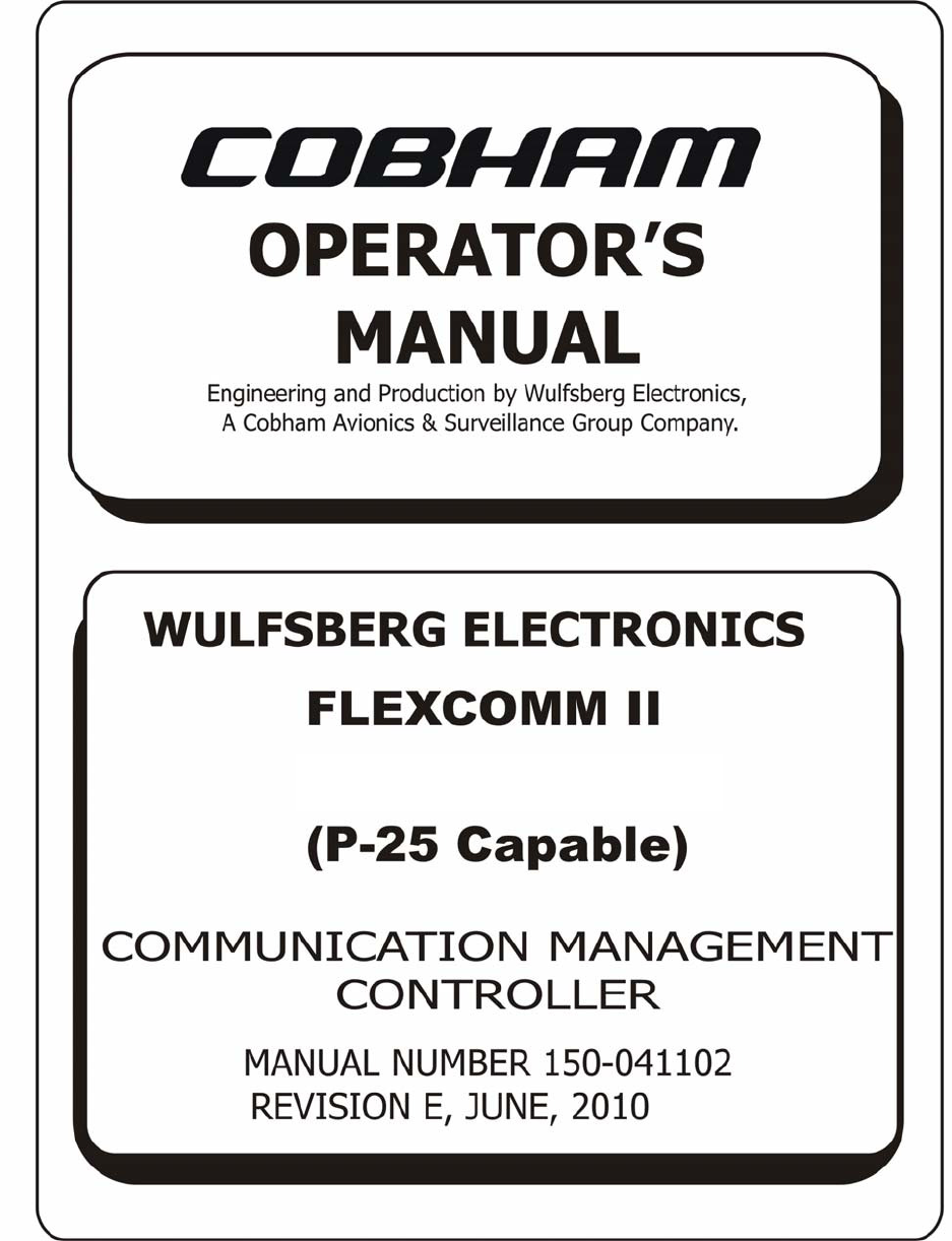
4. Configuration Availability
RT-5000 P/N options (with embedded XTS-3000 ITM modules)
PN 400-015525-XXXX -0611 -0711 -0811 -0911 -1011 -1111 -1211 -1311 -1411 -1511 -1611
138-174 -02 E -01 E E E E E E E -02 -01 -02
403-470 M M -04 M -03 M M M M M
450-520 P P P P -06 P -05 P P P
Internal
Transceiver
Module
(MHz) 764-806 T T T T T T -08 T -07 T -07 -07 - 0 8
DES. / XL / OFB Encryption X Y Y X Y Y X Y Y X Y Y X X X
D.V.P. / XL Encryption
D.V.I. / XL Encryption S S S S S S S S
SmartNet Trunking X L X L X L X L X L X L L L X X X
SmartZone Trunking O O O O O O X O X O X X X
OTAR X T T X T T X T T X T T X X X
RT-5000 P/N options (with embedded XTS-3000 ITM modules) cont’d
PN 400-015525-XXXX -1711 -1811 -1911 -2011 -2111 -2211 -2311 -2411 -2511 -2611 -2711
138-174
-01
-02
-01
-02
-01
-02
-01
-02
-01
E E
403-470
-03
-03
-04
-04
M M
450-520
-05
-05
-06
-06
-09
P P
Internal
Transceiver
Module
(MHz)
764-806
-08
T
-10
T
D.E.S. / XL / OFB Encryption X X X X X X X X X
Y Y
D.V.P. / XL Encryption X
D.V.I. / SL Encryption
S X S
SmartNet Trunking X X X X X X X X X X X X X X X X X X
L L
SmartZone Trunking X
O O
OTAR X X X X X X X X X X
T X T
Publication No. 150-041102 Page 15 of 88
Rev E C-5000 Operators Manual
FLEXCOMM I I
C-5000 ( P-25 Capable)
Operator’s Manual
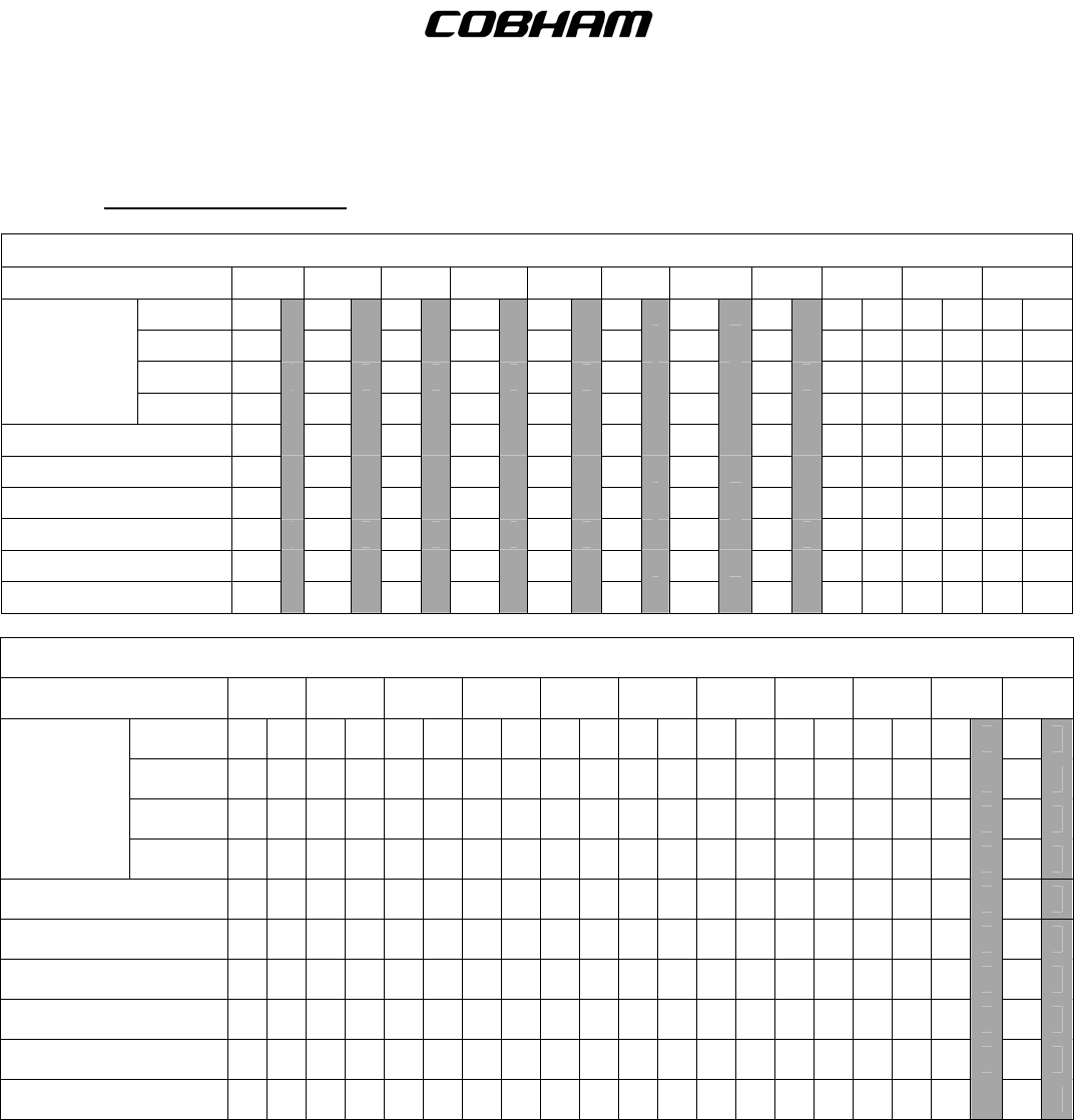
RT-5000 P/N options (with embedded XTS-3000 ITM modules) cont’d
PN 400-015525-XXXX -2811 -2911 -3011 -3111 -3211 -3311 -3411 -3511
138-174
-02
E
-12
E E E E
-16
E
-16
-16
403-470 M M M M
-15
M M
-20
450-520 P P P P P P
-18
Internal
Transceiver
Module
(MHz) 764-806 T T
-13
T
-14
T T T
A.E.S. Encryption Y Y Y Y Y X Y X X X X
D.E.S. / XL / OFB Encryption X X X X X X X X
D.V.P. / XL Encryption S X S S S S S
D.V.I. / XL Encryption L L L L L L
SmartNet Trunking O O O O O X O X X X
SmartZone Trunking T T T T X T T X
ASTRO P25 Trunking (3600 & 9600 BAUD) X X
OTAR X X X X X X X X
RT-5000 P/N options (with embedded XTS-5000 ITM modules)
PN 400-015525-
XXXX -5011 -5111 -5211 -5311 -5411 -5511 -5611 -5711 -5811 -5911 -6011
ITM Frequency 136-174 -04 -04 -04 E E E -04 E E -24 E -25 E -24
380-470 -11 M -10 M M M M M M -26
450-520 -16 P P -16 P P -23 P P P
806-870 -22 -22 T T T T T T T
A.E.S. Encryption X X X X X X X Y X Y X Y X Y Y X Y Y X X
D.E.S./XL/OFB Encryption X X X X X X X X X X X X X
D.V.P./XL Encryption S S S S X S S X S
D.V.I/ XL Encryption L L L L L L L
OTAR X X X X X X X O X O X O X O X O X O X O X X
SmartZone/Omnilink P25
Trunking (3600 & 9600 BAUD) X X X X X X X T X T X T X T X T X T X T X X
Vote Scan Mod
7
N/A Mod
7
Mod
7
Mod
7
Mod
7
N/A Mod
7 Mod
7 Mod
7 Mod
7 X
Mod
7 X X
Search and Rescue
Receivers 121.5
243.0
CH 16.0
CH 70.0
Continues.........
Publication No. 150-041102 Page 16 of 88
Rev E C-5000 Operators Manual

FLEXCOMM I I
C-5000 ( P-25 Capable)
Operator’s Manual
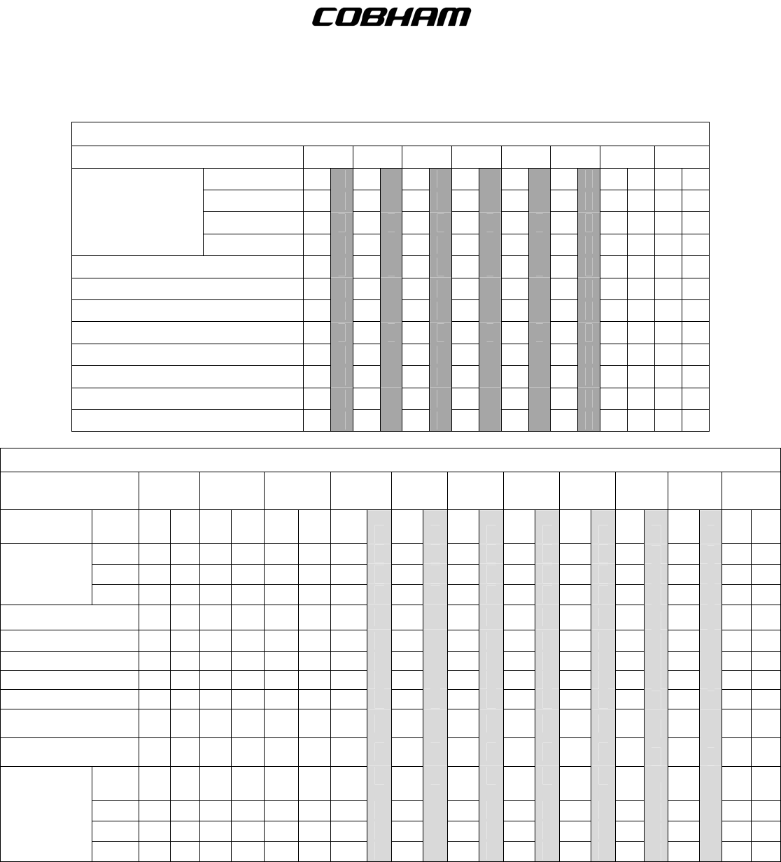
RT-5000 P/N options (with embedded XTS-5000 ITM modules) (cont’d)
PN 400-015525-XXXX -6111 -8211 -9999
ITM Frequency E
380-470 -10 -10 M
450-520 -27 P
806-870 -28 T
A.E.S. Encryption X X X X Y
D.E.S./XL/OFB Encryption X X X X
D.V.P./XL Encryption S
D.V.I/ XL Encryption L
OTAR X X X X O
SmartZone/Omnilink P25 Trunking
(3600 & 9600 BAUD) X X X X
T
Vote Scan MOD
7
MOD
7
Mod
7 N/A MOD
7
Search and Rescue
Receivers 121.5
X
243.0 X
CH 16.0 X
CH 70.0 X
Note: The ITM dash number e.g. -02, -22 represents the ITM module option installed.
Note: All P/N flavors come standard with the following features:
FM1 “Main” portion: 29.7-960 MHz FM & 29.7-400 MHz AM analog conventional capability.
FM2 “ITM” portion: Project 25 Common Air Interface (CAI); conventional FM analog;
FM digital (ASTRO).
Publication No. 150-041102 Page 17 of 88
Rev E C-5000 Operators Manual

FLEXCOMM I I
C-5000 ( P-25 Capable)
Operator’s Manual
5. Configuring the C-5000
A. Configuring the C-5000
Although Cobham highly recommends using the PC based Remote Programmer software to specify
the C-5000’s configuration, it can be specified from the front panel. The process is as follows.
(1) Ensure you are on the HOME PAGE.
(2) Press the PROG button. You will be prompted to enter a password, as follows.
E N T E R P A S S
W
ORD 2
# = . . .. <ENTER>
(3) Input the appropriate password using the keypad and press the ENTER button.
Note: Password 2 is “2222” by default.
(4) Press the MODE button until the following display page appears:
P R O G : 2 = N E X T 3 = B A C K
< E N T E R >= CFG SYSTE M
(5) Press the ENTER button. You will be prompted to enter a password, as follows:
E N T E R P A S S
W
ORD 1
# = . . .. <ENTER>
(6) Input the appropriate password and press the ENTER button.
Note: Password 1 is “1111” by default.
(7) The display will appear as follows:
S E T U P : 2 = N E X T 3 = B A C K
C 5 0 0 0 P / N = 1 220
Publication No. 150-041102 Page 18 of 88
Rev E C-5000 Operators Manual

FLEXCOMM I I
C-5000 ( P-25 Capable)
Operator’s Manual
(8) Use the cursor/value knobs to input the last four digits of your C-5000’s part number. Press
the MODE button to display the next menu page.
S E T U P : 2 = N E X T 3 = B A C K
E N T E R = SETUP RADI O # 1
(9) You can press the ENTER button to configure radio 1. Refer to the sections on configuring
RT-5000 and non-RT-5000 radios for details on these sub-menu pages. Press the MODE
button to display the next menu page.
S E T U P : 2 = N E X T 3 = B A C K
E N T E R = SETUP RADI O # 2
(10) You can press the ENTER button to configure radio 2. Refer to the sections on configuring
RT-5000 and non-RT-5000 radios for details on these sub-menu pages. Press the MODE
button to display the next menu page.
S E T U P : 2 = N E X T 3 = B A C K
E N T E R = C H G P A S S
W
OR D 1
(11) You can press the ENTER button to change the system configuration password. Refer to the
section on changing passwords for details on these sub-menu pages. Press the MODE
button to display the next menu page.
S E T U P : 2 = N E X T 3 = B A C K
E N T E R = C H G P A S S
W
OR D 2
(12) You can press the ENTER button to change the programming password. Refer to the section
on changing passwords for details on these sub-menu pages. Press the MODE button to
display the next menu page.
S E T U P : 2 = N E X T 3 = B A C K
E N T E R = SETUP MI SC.
(13) You can press the ENTER button to change miscellaneous system properties, such as
system encryption, side-tones, and de-emphasis. Refer to the section on miscellaneous
configuration options for details on these sub-menu pages. Press the MODE button to display
the next menu page.
Publication No. 150-041102 Page 19 of 88
Rev E C-5000 Operators Manual

FLEXCOMM I I
C-5000 ( P-25 Capable)
Operator’s Manual
S Y S T E M S E T U P M O D E
H O M E = E X I T 2 = R E V I E
W
(14) Press the HOME button to exit system configuration, or the MODE button to review current
settings.
B. Configuring the C-5000 to Control an RT-5000
This section covers the radio setup sub-menu pages. Refer to the section on configuring the C-5000
for details on how to reach these menu pages. This section assumes the C-5000 part number you
entered indicated an RT-5000 was present for Radio #1. We pick up at the following display page.
S E T U P : 2 = N E X T 3 = B A C K
E N T E R = SETUP RADI O # 1
(1) Press the ENTER button to begin configuring the RT-5000.
S Y S # 1 : 2 = N E X T 3 = B A C K
R T - 5 0 0 0 P / N = 5 01 1
(2) Use the cursor/value knobs to input the last four digits of your RT-5000’s part number. Press
the MODE button to display the next menu page.
Note: If the RT-5000 part number you enter is rejected, and you are sure you are entering a
valid part number, it is likely your flavor of RT-5000 was created after the C-5000
software was released. Since the C-5000 software has no knowledge of this part
number, it will reject it. Until your C-5000 software gets updated, you may enter an
“equivalent” part number. Refer to Appendix D for a complete list.
S Y S # 1 : 2 = N E X T 3 = B A C K
E N T E R = SETUP GUARD # 1
(3) This page will only display if the RT-5000 part number entered indicates a Guard receiver is
present. Pressing the ENTER button invokes the preset channel programming menu pages
for the Guard channel. Refer to the section on programming a preset channel for details since
programming a Guard channel is very similar to programming a preset channel.
Publication No. 150-041102 Page 20 of 88
Rev E C-5000 Operators Manual

FLEXCOMM I I
C-5000 ( P-25 Capable)
Operator’s Manual
S Y S # 1 : 2 = N E X T 3 = B A C K
R A D I O M O D E = 1
(4) This page will only display if the RT-5000 part number entered indicates an ITM is present.
Use the cursor/value knobs to select a value of 1 or 2. Mode 1 indicates that the ITM should
act as part of the main transceiver, i.e. the two transceivers appear to be a single unit. Mode
2 indicates that the ITM should not act as part of the main, i.e. it should behave as a Guard
receiver. Press the MODE button to display the next menu page.
S Y S # 1 : 2 = N E X T 3 = B A C K
Z O N E MODE = SIN G L E
(5) This page will only display if the RT-5000 part number entered indicates an ITM is present.
Use the cursor/value knobs to select a value of SINGLE or MULTI. SINGLE indicates that
the ITM is configured for single-zone mode, which means all channels (up to 256) are
programmed in zone 1. MULTI indicates that the ITM is configured for multi-zone mode,
which means channels are dispersed across multiple (up to 16) zones. Press the MODE
button to display the next menu page.
Note: Software versions 10 and below will not have this feature available.
I N C 2 = N E X T 3 = B A C K
D E C M A I N S Q L = 1 6 0
(6) This page allows you to set the RT-5000’s main receiver squelch level. Press the UPPER
SOFT KEY to increase the squelch level, or the LOWER SOFT KEY to decrease squelch
level. The squelch level determines the signal strength required by the RT-5000 to open its
audio gates, allowing you to hear what it is receiving. The larger the number, the stronger the
required signal. Press the MODE button to display the next menu page.
I N C 2 = N E X T 3 = B A C K
D E C G UARD SQL = 1 6 0
(7) This page allows you to set the RT-5000’s guard receiver squelch level. Press the UPPER
SOFT KEY to increase the squelch level, or the LOWER SOFT KEY to decrease squelch
level. The squelch level determines the signal strength required by the RT-5000 to open its
audio gates, allowing you to hear what it is receiving. The larger the number, the stronger the
required signal. Press the MODE button to display the next menu page.
Publication No. 150-041102 Page 21 of 88
Rev E C-5000 Operators Manual

FLEXCOMM I I
C-5000 ( P-25 Capable)
Operator’s Manual
S E T UP RAD I O # 1
H O M E = E X I T 2 = R E V I E
W
(8) Press the HOME button to exit the radio setup menu pages, or press the MODE button to
review the current settings.
C. Configuring the C-5000 to Control A Non RT-5000
This section covers the radio setup sub-menu pages. Refer to the section on configuring the C-5000
for details on how to reach these menu pages. This section assumes the C-5000 part number you
entered indicated a Flitecomm or Flexcomm I radio was present on radio #2. We pick up at the
following display page:
S E T U P : 2 = N E X T 3 = B A C K
E N T E R = SETUP RADI O # 2
(1) Press the ENTER button to begin configuring the radio.
S Y S # 2 : 2 = N E X T 3 = B A C K
R T - 30 PRESENT - N O
(2) Use the cursor/value knobs to tell the C-5000 if an RT-30 is present. Press the MODE button
to display the next menu page.
S Y S # 2 : 2 = N E X T 3 = B A C K
R T - 1 18 PRESENT - N O
(3) Use the cursor/value knobs to tell the C-5000 if an RT-118 is present. Press the MODE
button to display the next menu page.
S Y S # 2 : 2 = N E X T 3 = B A C K
R T - 1 38 PRESENT - Y E S
(4) Use the cursor/value knobs to tell the C-5000 if an RT-138 is present. Press the MODE
button to display the next menu page.
Publication No. 150-041102 Page 22 of 88
Rev E C-5000 Operators Manual

FLEXCOMM I I
C-5000 ( P-25 Capable)
Operator’s Manual
S Y S # 2 : 2 = N E X T 3 = B A C K
R T - 1 3 8 F PRESENT - N O
(5) Use the cursor/value knobs to tell the C-5000 if an RT-138F is present. Press the MODE
button to display the next menu page.
S Y S # 2 : 2 = N E X T 3 = B A C K
R T - 4 50 PRESENT - N O
(6) Use the cursor/value knobs to tell the C-5000 if an RT-450 is present. Press the MODE
button to display the next menu page.
S Y S # 2 : 2 = N E X T 3 = B A C K
R T - 4 0 6 F PRESENT - N O
(7) Use the cursor/value knobs to tell the C-5000 if an RT-406F is present. Press the MODE
button to display the next menu page.
S Y S # 2 : 2 = N E X T 3 = B A C K
R T - 9 6 0 0F PRESENT - N O
(8) Use the cursor/value knobs to tell the C-5000 if an RT-9600F is present. Press the MODE
button to display the next menu page.
S Y S # 2 : 2 = N E X T 3 = B A C K
R T - 9 6 0 0 PRESENT - N O
(9) Use the cursor/value knobs to tell the C-5000 if an RT-9600 is present. Press the MODE
button to display the next menu page.
S Y S # 2 : 2 = N E X T 3 = B A C K
R T - 7 2 0 0 PRESENT - N O
(10) Use the cursor/value knobs to tell the C-5000 if an RT-7200 is present. Press the MODE
button to display the next menu page.
Publication No. 150-041102 Page 23 of 88
Rev E C-5000 Operators Manual

FLEXCOMM I I
C-5000 ( P-25 Capable)
Operator’s Manual
S Y S # 2 : 2 = N E X T 3 = B A C K
G U A R D # 1 PRESENT - Y E S
(11) Use the cursor/value knobs to tell the C-5000 if a Guard is present. Press the MODE button
to display the next menu page.
S Y S # 2 : 2 = N E X T 3 = B A C K
E N T E R = SETUP GUARD # 1
(12) This page only appears if a guard is present. Press the ENTER button to configure the first
Guard channel. Refer to the preset channel programming section for details on the menu
pages that appear. Press the MODE button to display the next menu page.
S Y S # 2 : 2 = N E X T 3 = B A C K
G U A R D # 2 PRESENT - Y E S
(13) This page only appears if a second Guard is possible. Use the cursor/value knobs to tell the
C-5000 if a second Guard is present. Press the MODE button to display the next menu page.
S Y S # 2 : 2 = N E X T 3 = B A C K
E N T E R = SETUP GUARD # 2
(14) This page only appears if a second guard is present. Press the ENTER button to configure
the second Guard channel. Refer to the preset channel programming section for details on
the menu pages that appear. Press the MODE button to display the next menu page.
S Y S # 2 : 2 = N E X T 3 = B A C K
T O N E B OARD CT CSS - N O
(15) Use the cursor/value knobs to tell the C-5000 if an internal CTCSS tone board is
present.(Represented by a “3” in the C-5000 part number, i.e. 31300-XXXX-X333). Press the
MODE button to display the next menu page.
S Y S # 2 : 2 = N E X T 3 = B A C K
T O N E B OARD DCS - N O
Publication No. 150-041102 Page 24 of 88
Rev E C-5000 Operators Manual

FLEXCOMM I I
C-5000 ( P-25 Capable)
Operator’s Manual
(16) Use the cursor/value knobs to tell the C-5000 if an internal DCS tone board is present.
(Represented by a “3” in the C-5000 part number, i.e. 31300-XXXX-X333). Press the MODE
button to display the next menu page.
S E T UP RAD I O # 2
H O M E = E X I T 2 = R E V I E
W
(17) Press the HOME button to exit the radio setup menu pages, or press the MODE button to
review the current settings.
D. Setting Passwords
This section covers the password setup sub-menu pages. Refer to the section on configuring the C-
5000 for details on how to reach these menu pages. This section assumes we want to change
password 1. The process is the same for password 2. We pick up at the following display page.
S E T U P : 2 = N E X T 3 = B A C K
E N T E R = C H G P A S S
W
OR D 1
(1) Press the ENTER button to begin the password changing process. The display will appear as
follows:
E N T E R N E
W
PASS
W
OR D 1
# = . . .. <ENTER>
(2) Use the keypad to input the new password, and press the ENTER button.
B A C K V E R I F Y I N P U T
# = . . .. <ENTER>
(3) Use the keypad to re-input the new password, and press the ENTER button. This second
entry is for verification. If you entered an inconsistent password, your input will be erased,
and you may try again. Once you have entered the same password on both pages, it will be
changed, and the display will revert to the following:
S E T U P : 2 = N E X T 3 = B A C K
E N T E R = C H G P A S S
W
OR D 1
Publication No. 150-041102 Page 25 of 88
Rev E C-5000 Operators Manual

FLEXCOMM I I
C-5000 ( P-25 Capable)
Operator’s Manual
E. Setting Miscellaneous Configuration Options
This section covers the miscellaneous setup sub-menu pages. Refer to the section on configuring the
C-5000 for details on how to reach these menu pages. We pick up at the following display page:
S E T U P : 2 = N E X T 3 = B A C K
E N T E R = SETUP MI SC.
(1) Press the ENTER button to begin configuring miscellaneous options.
S E T U P : 2 = N E X T 3 = B A C K
D I M K E Y M O D E - M UT E
(2) This page only appears if utilizing software 11 and above. Use the cursor/value knobs to tell
the C-5000 if the DIM key should be used for the DIM function or the MUTE function. When
configured for MUTE, pressing the DIM key will mute audio from the non-active receivers.
Press the MODE button to display the next menu page.
S E T U P : 2 = N E X T 3 = B A C K
M I C MODE -SIN G L E
(3) This page only appears if using software 11 and above. Use the cursor/value knobs to tell the
C-5000 if it has one or two microphones connected to it. When configured for SINGLE, the C-
5000 will operate in single-mic mode. Press the MODE button to display the next menu page.
S E T U P : 2 = N E X T 3 = B A C K
S Y S T E M E N C R Y P T - N O
(4) Use the cursor/value knobs to tell the C-5000 if external encryption is available. This option
pertains only to a separate encryption device, i.e. one that is not part of the C-5000 or any of
the transceivers. A KY-58 device is a typical example. Press the MODE button to display the
next menu page.
S E T U P : 2 = N E X T 3 = B A C K
C - 5 0 0 0 S I D E T O N E - N O
(5) This page only appears if system encryption is available. Use the cursor/value knobs to tell
the C-5000 if it should use side-tones. Press the MODE button to display the next menu
page.
Publication No. 150-041102 Page 26 of 88
Rev E C-5000 Operators Manual

FLEXCOMM I I
C-5000 ( P-25 Capable)
Operator’s Manual
S E T U P : 2 = N E X T 3 = B A C K
C - 5 0 0 0 D E E M P H - N O
(6) This page only appears if system encryption is available. Use the cursor/value knobs to tell
the C-5000 if it should use de-emphasis. Press the MODE button to display the next menu
page.
M I SC SETUP
H O M E = E X I T 2 = R E V I E
W
(7) Press the HOME button to exit the miscellaneous configuration menu pages, or the MODE
button to review current settings.
F. Configuring the C-5000 Using a PC
Cobham highly recommends using the PC based Remote Programmer (RP) software to specify the
C-5000’s configuration. The Remote Programmer software offers several advantages over using
theC-5000’s front panel which includes:
(1) Allowing you to specify a C-5000’s configuration in less time.
(2) Enhanced error checking reduces the likelihood of specifying an incorrect configuration.
(3) A configuration can be specified once and loaded to multiple C-5000’s, saving huge amounts
of data entry time.
(4) Configurations can be saved, archived, and backed-up, reducing the likelihood of lost data.
(5) Configurations can be uploaded from the C-5000’s as well, saving data entry time on existing
configurations.
Refer to the Remote Programmer software’s user manual 150-041374 for details on how to specify C-
5000 configurations in RpWin.
G. Downloading a Configuration from RP into the C-5000
The C-5000 continuously polls the data port on the front panel for incoming data, so all the user has
to do is initiate the download from RpWin. Refer to RpWin’s user manual for details on how to initiate
a download. Once the communication channel is open, the C-5000’s display will change to the
following:
M E M O RY TRANSFER
R E C E I V I NG BL OCK= 0 0 0
Publication No. 150-041102 Page 27 of 88
Rev E C-5000 Operators Manual

FLEXCOMM I I
C-5000 ( P-25 Capable)
Operator’s Manual
The 3-digit hexadecimal number to the right of the display on the lower line will increment from 000 to
2FF while the download is in progress. When the download is complete, the C-5000 will automatically
restart.
H. Uploading a Configuration from the C-5000 into RpWin
The C-5000’s current configuration can be uploaded into the RpWin software as follows:
(1) From the HOME page, press the PROG button, and enter the appropriate password.
(2) Press the MODE button until the following display page appears:
P R O G : 2 = N E X T 3 = B A C K
< E N T E R > = R P L O A D
(3) Press the ENTER button to display the following page:
M E M O RY TRANSFER
S T A R T SENDING
(4) Ensure the serial cable is connected to both the PC and the C-5000. Ensure the RpWin
software is ready to receive data. Refer to RpWin’s user manual for details on how to prepare
RpWin to receive data. Press the LOWER SOFT button on the C-5000 to initiate the transfer.
Once the communication channel is open, the C-5000’s display will change to the following:
M E M O RY TRANSFER
S E N D I NG BLOCK= 0 0 0
(5) The 3-digit hexadecimal number to the right of the display on the lower line will increment
from 000 to 2FF while the upload is in progress. When the upload is complete, the C-5000’s
display will return to the following:
P R O G : 2 = N E X T 3 = B A C K
< E N T E R > = R P L O A D
(6) Press the HOME button to return to the HOME PAGE.
Note: You will most likely want to save the uploaded data to a disk file on the PC. Refer to
RpWin’s user manual (150-041374) for details on how to do this.
Publication No. 150-041102 Page 28 of 88
Rev E C-5000 Operators Manual

FLEXCOMM I I
C-5000 ( P-25 Capable)
Operator’s Manual
I. Entering CPS Load Mode
Digital RT-5000’s must have the ITM(s) loaded with Motorola CPS before being able to TX/RX on
digital channels. Enter into CPS Load Mode by doing the following:
(1) From the HOME page, press the PROG button, and enter the appropriate password.
(2) Press the MODE button until the following display page appears:
P R O G : 2 = N E X T 3 = B A C K
< E N T E R > = C P S L O A D
(3) Press ENTER button to enter the CPS LOAD screen:
S T A R T C P S L O A D
R A D I O = 1 I T M = V H F 1 3 8
(4) Use the cursor to select either Radio 1 or 2 (if available), and between VHF or UHF ITM
depending on RT-5000 model number:
S T A R T C P S L O A D
R A D I O = 1 I T M = U H F 8 0 0
(5) Press START to open the CPS data lines and communicate between the laptop and the RT-
5000. When finished press END, and HOME twice to return:
E N D CPS LOAD
R A D I O # 1 I N C P S M O D E
J. KVL Load
In order to load encryption keys using a KVL data loader, you must enter KVL LOAD MODE by
performing the following procedures:
(1) From the HOME page, press the PROG button, and enter the appropriate password.
(2) Press the MODE button until the following display page appears:
Publication No. 150-041102 Page 29 of 88
Rev E C-5000 Operators Manual

FLEXCOMM I I
C-5000 ( P-25 Capable)
Operator’s Manual
P R O G : 2 = N E X T 3 = B A C K
< E N T E R > = K V L L O A D
(3) Press ENTER button to enter the KVL LOAD screen:
S T A R T K V L L O A D
R A D I O = 1 I T M = V H F 1 3 8
(4) Use the cursor to select either Radio 1 or 2 (if available), and between VHF or UHF ITM
depending on RT-5000 model number:
S T A R T K V L L O A D
R A D I O = 1 I T M = U H F 8 0 0
(5) Press START to open the KVL data lines and load the encryption keys into the RT-5000.
When finished press END, and HOME twice to return:
E N D KVL LOAD
R A D I O # 1 I N K V L M O D E
NOTE: Unit power must be cycled BEFORE utilizing the radio for communications after
performing a key load.
K. KEY Erase
In order to erase loaded encryption keys, you must enter KEY ERASE MODE by performing the
following procedures:
(1) From the HOME page, press the PROG button, and enter the appropriate password.
(2) Press the MODE button until the following display page appears:
Publication No. 150-041102 Page 30 of 88
Rev E C-5000 Operators Manual

FLEXCOMM I I
C-5000 ( P-25 Capable)
Operator’s Manual
P R O G : 2 = N E X T 3 = B A C K
< E N T E R > = K E Y E R A S E
(3) Press ENTER button to enter the KEY ERASE screen:
S T A R T KEY ERASE
R A D I O = 1 I T M = V H F 1 3 8
(4) Use the cursor to select either Radio 1 or 2 (if available), and between VHF or UHF ITM
depending on RT-5000 model number:
S T A R T KEY ERASE
R A D I O = 1 I T M = U H F 8 0 0
(5) Press START to erase the encryption keys. When finished press END, and HOME twice to
return:
E N D KEY ERASE
R A D I O # 1 K E Y S E R A S E D
6. CPS Software Description and Programming
A. Before You Begin
To program the ITM(s) inside the RT-5000 the user must use a Windows based PC and Motorola’s
CPS software. Users must obtain their own copies of the software from Motorola as Cobham cannot
supply it. The programming of the ITM requires three basic steps. First, enter the information that has
to do with the setup of the way the RT-5000 communicates with the ITM. Second enter channel
information, or what Motorola calls “Personalities”, and finally assign the personalities to Zones and
Channels. It may help tremendously to enlist the help of an experienced CPS programmer.
Note: Do Not simply write a portable file into the RT-5000 because this will overwrite data that
should not be altered.
If your agency uses Motorola XTS-X000 model handhelds, the simplest way to get started is to use
an archive from a known properly programmed XTS-X000. Then transfer a single channel to the
Publication No. 150-041102 Page 31 of 88
Rev E C-5000 Operators Manual
FLEXCOMM I I
C-5000 ( P-25 Capable)
Operator’s Manual
resident archive stored in the RT-5000 ITM from the factory. Add more channels once the first one is
proven.
Alternatively, the ITM comes from the factory with all the necessary information loaded in it for basic
operation. The user only needs to load system information such as USER ID’s, personalities,
and zone/channel allocation. Once an archive for an ITM is established, it can be cloned to other
ITM’s in other RT-5000’s of the same flavor.
The CPS software only allows the programmer to see and change functions that are available with
the hardware it is trying to program. As such, not all of the screens listed will be seen for every
model of ITM.
There are (2) versions of CPS that may apply to the RT-5000 depending upon P/N as follows:
RT-5000 P/N 400-015525-0611 through -3511 uses CPS for XTS-3000 Portable radios. CPS P/N
RVN4182, which is 1 portion of a 2 disk set ordered under P/N RVN4184.
Note: There is no need for a RIB (Radio Interface Box) when using the RT-5000. The RIB is
already built into the radio.
RT-5000 P/N 400-015525-5011 and above uses CPS for XTS-5000 Portable Radios. CPS P/N
RVN4181, which is 1 portion of a 2 disk set ordered under P/N RVN4186.
Motorola CPS Ordering Information:
North American Customers: 1-800-422-4210
U.S.A. Federal Customers: 1-800-826-1913
International Customers: 1-847-538-8023
B. CPS Code PMA File Details
For a detailed description and help understanding CPS and the numerous options within you may
refer to the built in CPS help tool and tutorials. Further definition of each entry may be obtained by
pressing F1 with the entry highlighted on the screen.
Note: The following is a general guideline for programming the RT-5000 ITM’s using the CPS
software. Not all of the RT-5000 flavors will follow the same settings as outlined in this
manual due to various setting requirements for each specific flavor. Please remember
to never modify the Controls and Display and Menu Options unless instructed to do so, as
they are set at the factory per the RT-5000 flavor requirement.
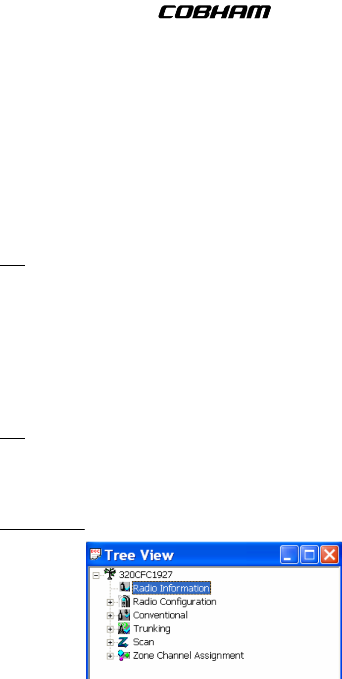
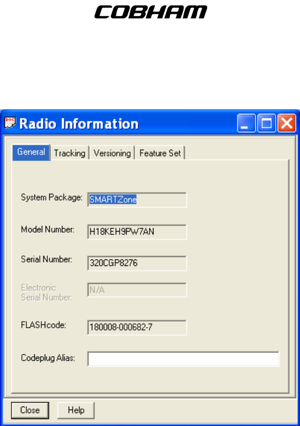
7. Radio Information – Contains key elements describing the configuration of the module.
Publication No. 150-041102 Page 32 of 88
Rev E C-5000 Operators Manual
FLEXCOMM I I
C-5000 ( P-25 Capable)
Operator’s Manual
A. General – This menu contains the model number, serial number, FLASHcode version, and an
assignable codeplug alias.
B. Tracking – Allows you to view information regarding the last programmed date, time, and source
of CPS and FLASHport.
C. Versioning – Allows you to view the latest software versions applied to the codeplug and ITM.
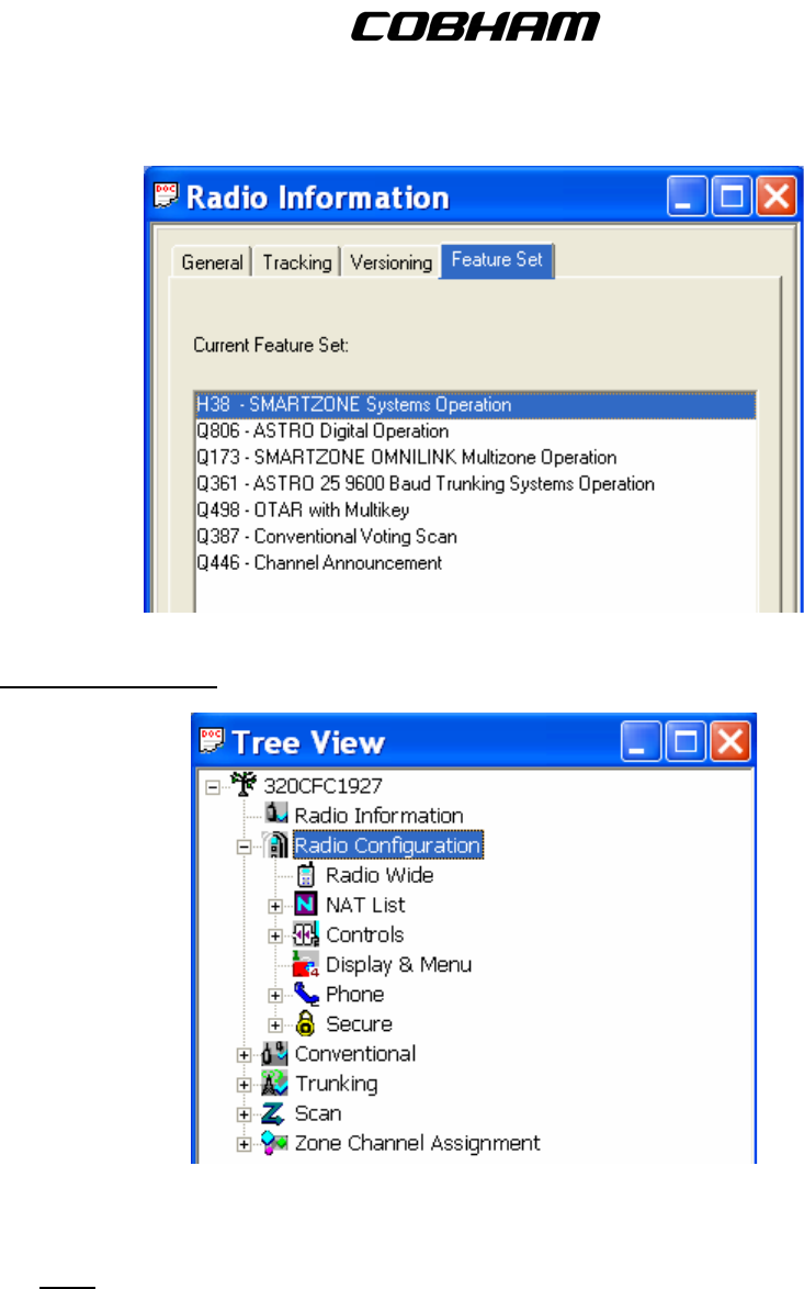
D. Feature Set – Allows you to view the feature set that is installed in the ITM.
Publication No. 150-041102 Page 33 of 88
Rev E C-5000 Operators Manual
FLEXCOMM I I
C-5000 ( P-25 Capable)
Operator’s Manual
8. Radio Configuration – Menu contains elements that affect the overall operation of the radio.
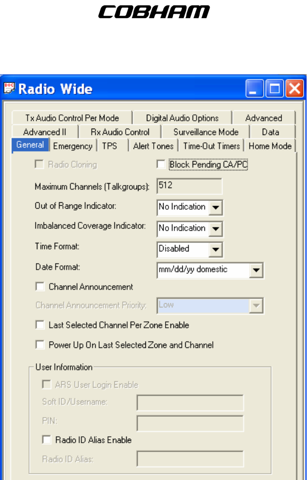
A. Radio Wide – These menus allow you to modify settings that affect the overall operation of the
radio.
Note: These are necessary to allow integration of the ITM with the C-5000/RT-5000 system.
(1) General – This menu contains general elements of the ITM.
Publication No. 150-041102 Page 34 of 88
Rev E C-5000 Operators Manual
FLEXCOMM I I
C-5000 ( P-25 Capable)
Operator’s Manual
Note: DO NOT change any of these settings from the defaults.
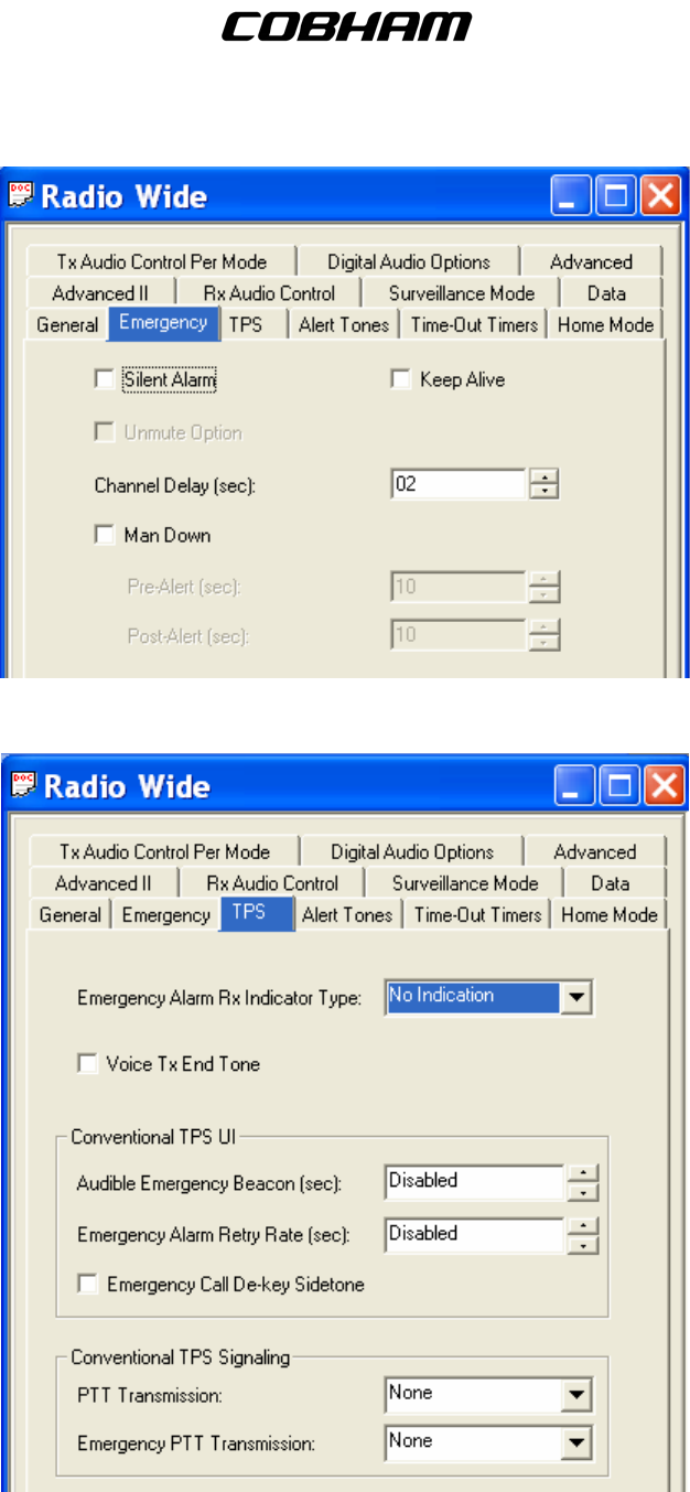
(2) Emergency –This menu is for setting up the emergency features of the ITM.
Publication No. 150-041102 Page 35 of 88
Rev E C-5000 Operators Manual
FLEXCOMM I I
C-5000 ( P-25 Capable)
Operator’s Manual
(3) TPS – This menu allows you to modify Tactical Public Safety (TPS) elements.
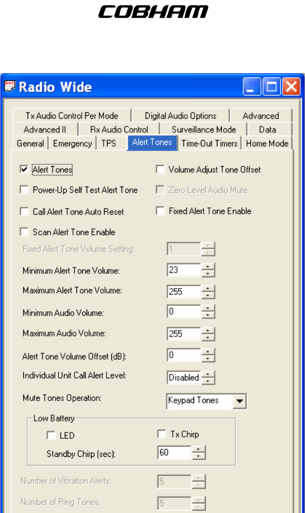
(4) Alert Tones – This menu allows you to modify alert tone elements radio wide.
Publication No. 150-041102 Page 36 of 88
Rev E C-5000 Operators Manual
FLEXCOMM I I
C-5000 ( P-25 Capable)
Operator’s Manual
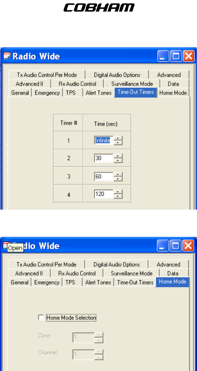
(5) Time-Out Timers – This menu allows you to modify port timing elements.
Publication No. 150-041102 Page 37 of 88
Rev E C-5000 Operators Manual
FLEXCOMM I I
C-5000 ( P-25 Capable)
Operator’s Manual
(6) Home Mode – This menu allows you to change Home Mode elements radio wide.
Note: DO NOT enable this option.
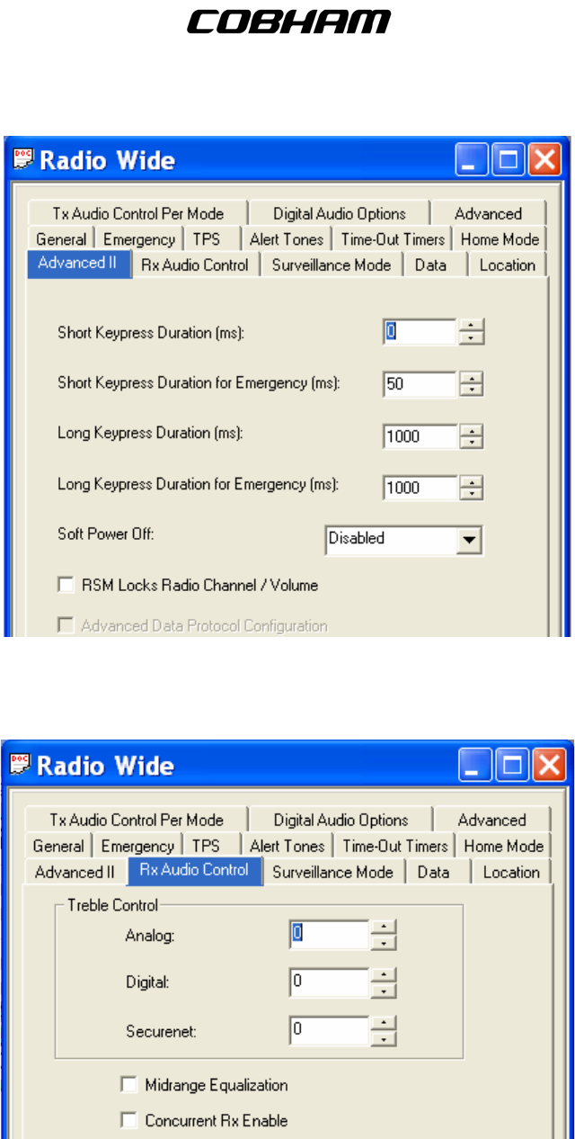
(7) Advanced II – This menu allows you to change advanced elements radio wide.
Publication No. 150-041102 Page 38 of 88
Rev E C-5000 Operators Manual
FLEXCOMM I I
C-5000 ( P-25 Capable)
Operator’s Manual
(8) RX Audio Control – This menu allows you to change received audio control elements radio
wide.
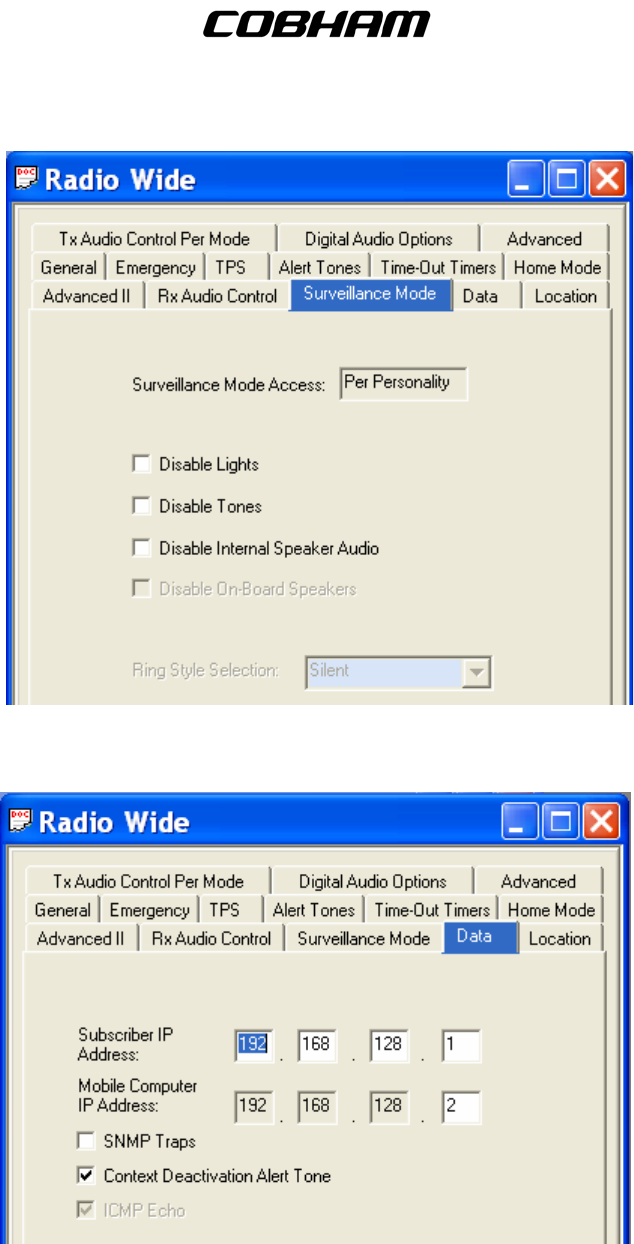
(9) Surveillance Mode – This menu allows you to change Surveillance Mode elements.
Publication No. 150-041102 Page 39 of 88
Rev E C-5000 Operators Manual
FLEXCOMM I I
C-5000 ( P-25 Capable)
Operator’s Manual
(10) Data – This menu allows you to modify the Radio Wide Data used for the Trunking Systems.
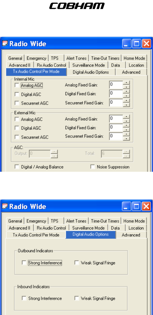
(11) TX Audio Control Per Mode – This menu allows you to chance transmit audio control
elements radio wide.
Publication No. 150-041102 Page 40 of 88
Rev E C-5000 Operators Manual
FLEXCOMM I I
C-5000 ( P-25 Capable)
Operator’s Manual
(12) Digital Audio Options – This menu allows you to enable the feedback indication of the
received audio quality.
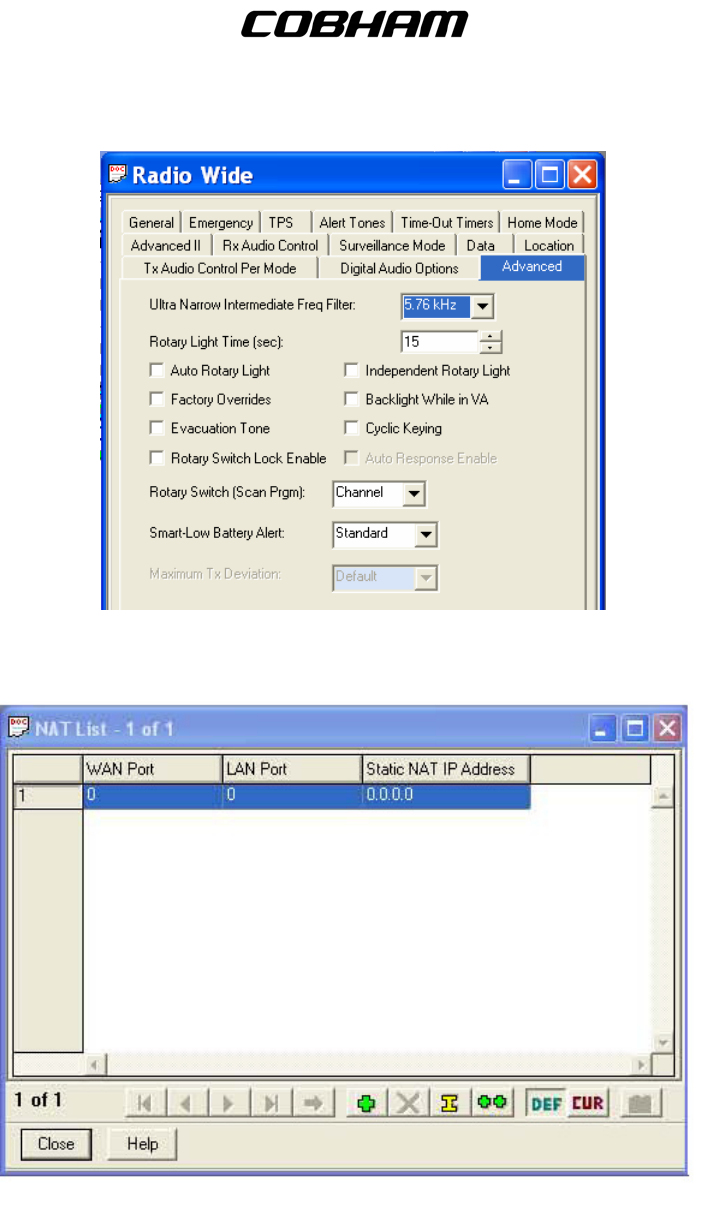
(13) Advance
d - These are necessary to allow integration of the ITM with the RT-5000 system.
Publication No. 150-041102 Page 41 of 88
Rev E C-5000 Operators Manual
FLEXCOMM I I
C-5000 ( P-25 Capable)
Operator’s Manual
B. NAT List – This allows you to configure the Network Address Translation.
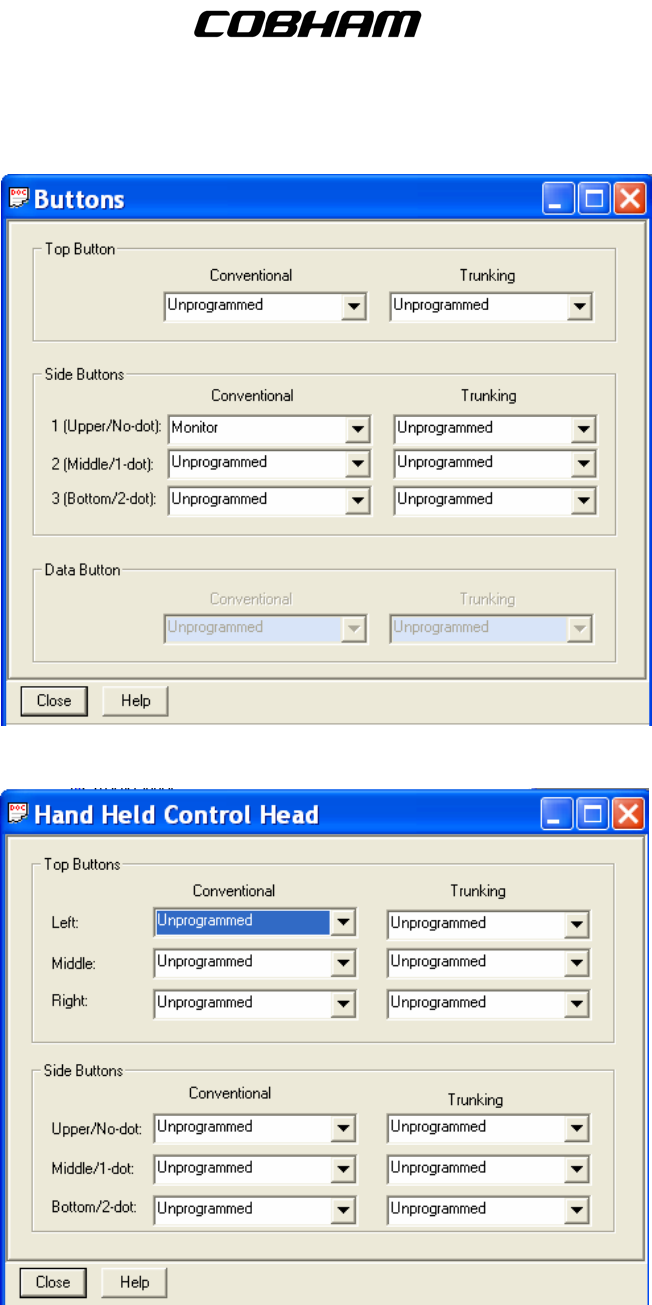
C. Controls – This contains the Display and Menu options. Settings should be as follows:
(1) Buttons – These are set at the factory level and should remain as follows:
Publication No. 150-041102 Page 42 of 88
Rev E C-5000 Operators Manual
FLEXCOMM I I
C-5000 ( P-25 Capable)
Operator’s Manual
.
(2) Hand Held Control Head - ALL entries should remain set to UNPROGRAMMED.
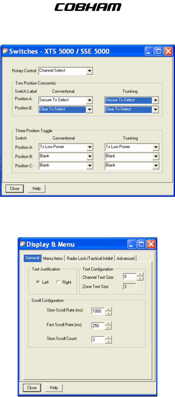
(3) Switches – Settings should be as follows:
Publication No. 150-041102 Page 43 of 88
Rev E C-5000 Operators Manual
FLEXCOMM I I
C-5000 ( P-25 Capable)
Operator’s Manual
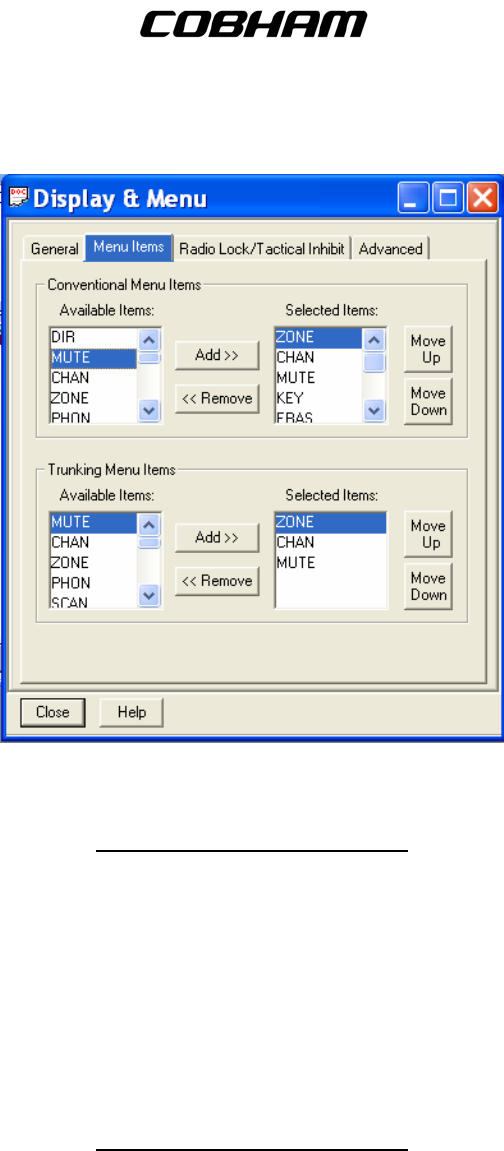
D. Display and Menu
(1) General – This menu allows you to modify basic elements of the radio’s display. Here you
can also change the zone and channel text size.
(2) Menu Items - This menu sets up some very critical items in order for the RT-5000 to
communicate with the ITM.
Publication No. 150-041102 Page 44 of 88
Rev E C-5000 Operators Manual
FLEXCOMM I I
C-5000 ( P-25 Capable)
Operator’s Manual
****VERY IMPORTANT****: THESE SETTINGS MUST BE EXACTLY AS SHOWN !!!!!
For ITM’s with encryption set up as follows:
Conv Item Trunk Item
ZONE ZONE
CHAN CHAN
MUTE MUTE
KEY
ERAS
REKY
DIR
DIR
DIR
For ITM’s without encryption set up as follows:
Conv Item Trunk Item
ZONE ZONE
CHAN CHAN
MUTE MUTE
DIR
DIR
DIR
DIR
DIR
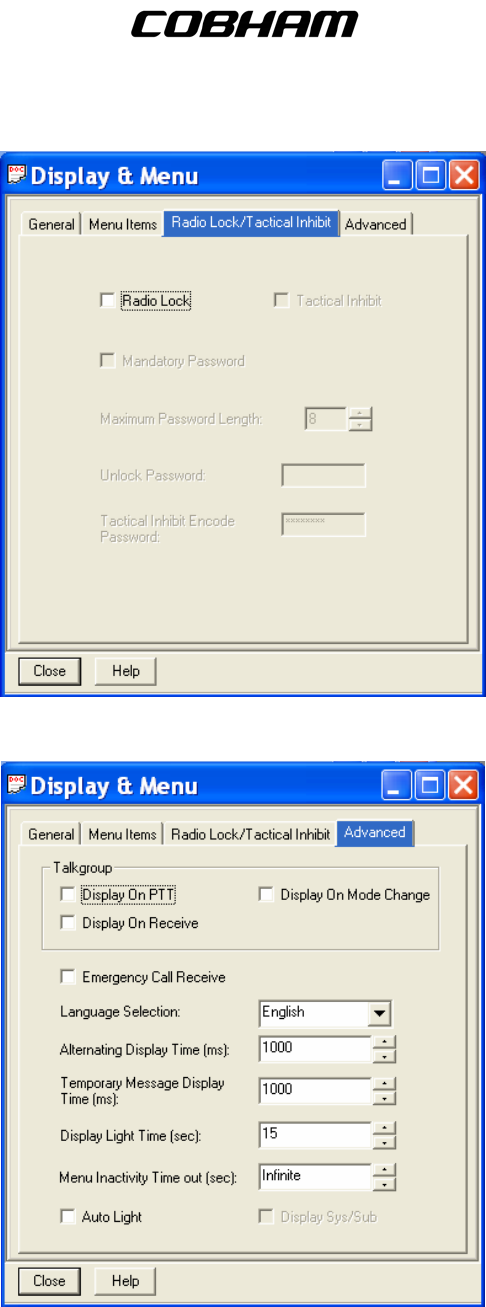
(3) Radio Lock – This menu allows you to modify the radio’s security elements.
Publication No. 150-041102 Page 45 of 88
Rev E C-5000 Operators Manual
FLEXCOMM I I
C-5000 ( P-25 Capable)
Operator’s Manual
(4) Advanced – This menu allows you to modify the radio’s display elements.
E. Phone – Contains menus to configure the system to use DTMF codes.
Publication No. 150-041102 Page 46 of 88
Rev E C-5000 Operators Manual
FLEXCOMM I I
C-5000 ( P-25 Capable)
Operator’s Manual
(1) Phone Configuration – This menu allows you to modify the radio’s Phone configuration
settings applied to Conventional and Trunking personalities.
(2) DTMF Codes – This menu allows you to configure the codes used by the radio when utilizing
a Phone System.
(3) Phone Number – This menu allows you to select the DTMF number for the Phone Number
used by the radio.
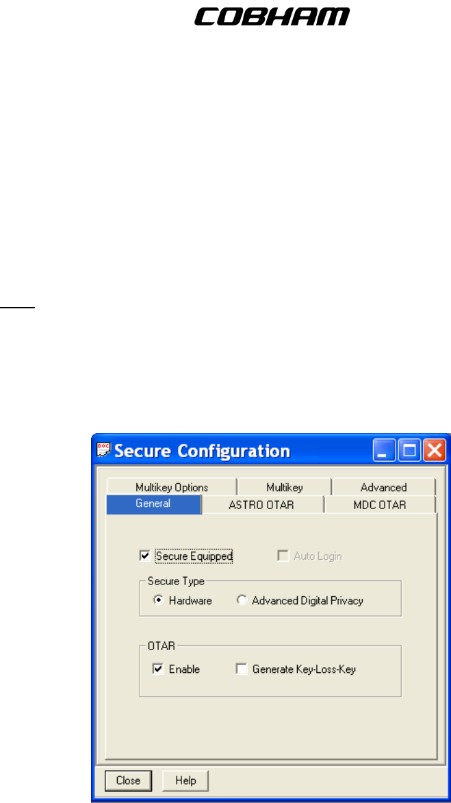
F. Secure –The settings in these menus control the overall behavior of the radio when operating in
the secure mode.
Note: Some of these settings will vary depending on the encryption system. Settings should be
as follows:
(1) Secure Configuration – Contains menus to modify secure TX and RX elements.
(a) General – This menu allows you to modify the General options that apply to the Secure
Configuration.
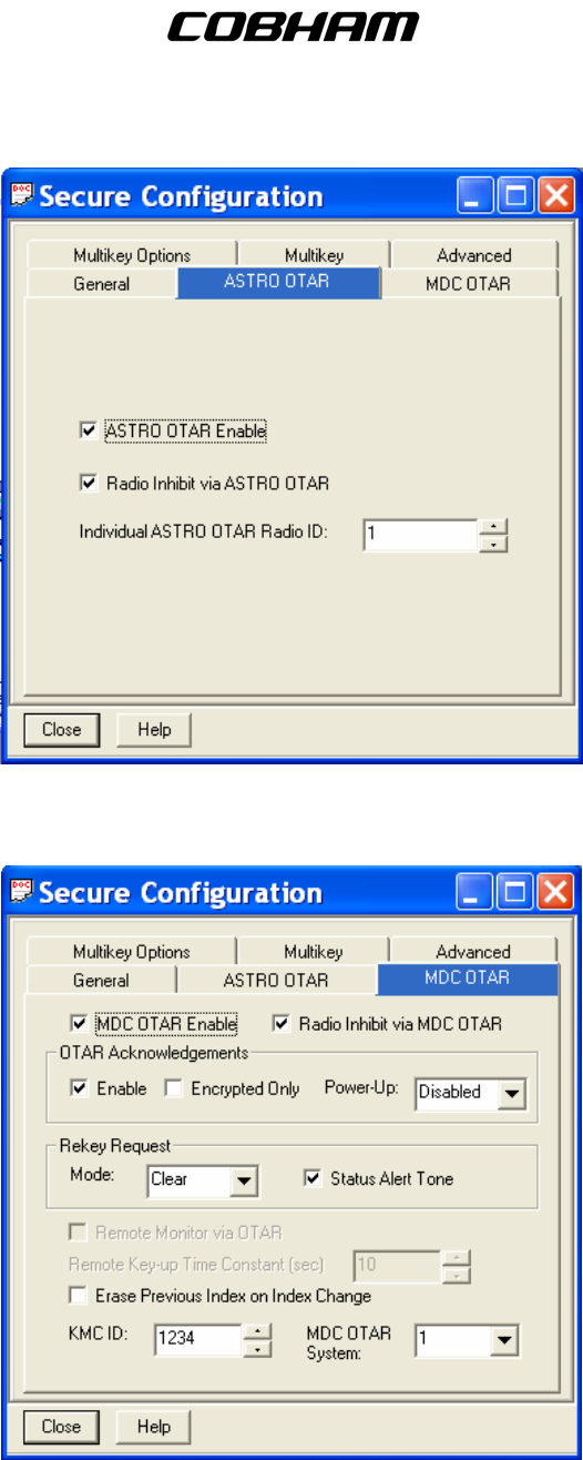
(b) ASTRO OTAR –This page controls all ASTRO (Digital) specific OTAR settings.
Publication No. 150-041102 Page 47 of 88
Rev E C-5000 Operators Manual
FLEXCOMM I I
C-5000 ( P-25 Capable)
Operator’s Manual
(c) MDC OTAR –This page controls all radio settings specifically applicable to MDC
(Analog) OTAR operations.
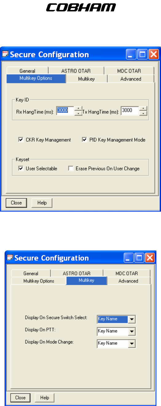
(d) Multikey Options – This screen controls the number of User Selectable Encryption Keys,
the CKR (Common Key Reference) and Key Names.
Publication No. 150-041102 Page 48 of 88
Rev E C-5000 Operators Manual
FLEXCOMM I I
C-5000 ( P-25 Capable)
Operator’s Manual
(e) Multikey –This page controls additional items necessary for the OTAR and secure
functions to operate properly. These are necessary to allow integration of the ITM
module with the RT-5000 Flexcomm system. DO NOT make changes to these unless
instructed.
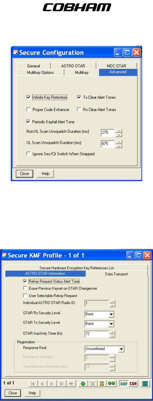
(f) Advanced – This menu allows you to modify the Advanced options that apply to the
Secure Configuration.
Publication No. 150-041102 Page 49 of 88
Rev E C-5000 Operators Manual
FLEXCOMM I I
C-5000 ( P-25 Capable)
Operator’s Manual
(2) Secure Multikey List – This allows you to modify multiply encryption keys for Secure
communication.
(3) Secure KMF Profile – This menu allows you to modify the Secure Key Management’s
elements.
(a) ASTRO OTAR Information – This menu allows you to modify ASTRO and OTAR
elements.
(b) Data Transport – This menu allows you to modify elements used in sending Key
Management Messages.
Publication No. 150-041102 Page 50 of 88
Rev E C-5000 Operators Manual
FLEXCOMM I I
C-5000 ( P-25 Capable)
Operator’s Manual
(c) Secure Hardware Encryption Key Reference List – Allows you to modify the set of
Common Key References (CKR) the Key Management Facility (KMF) can attain.
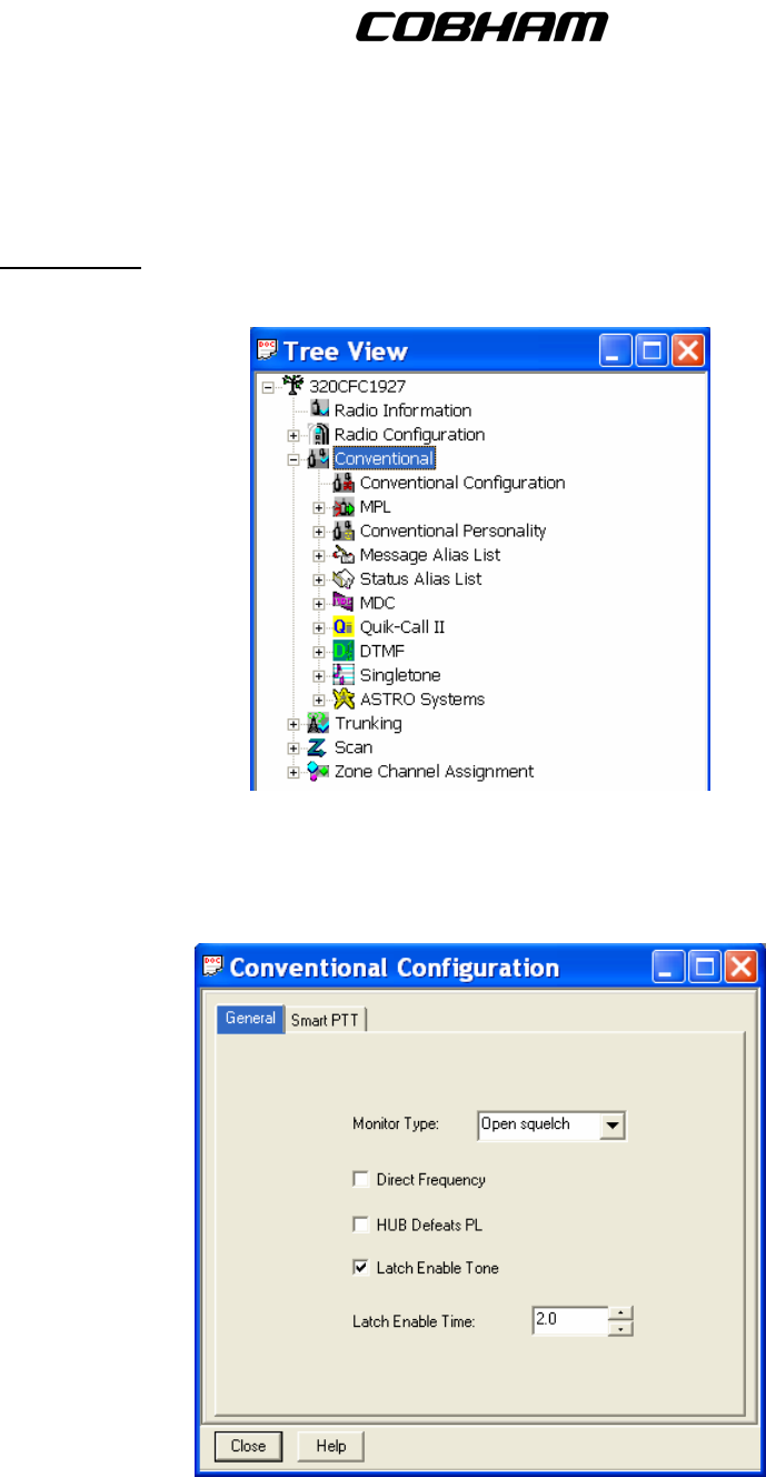
9. Conventional - All the aspects of any given channel are assigned to a personality numbered 1
through 255. These menus allow the user to modify the settings for the Conventional Personalities.
A. Conventional Configuration – These menus are used to configure the conventional
personalities.
(1) General – This menu allows general configuration of Conventional elements.
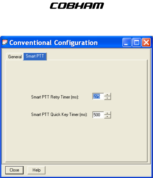
(2) Smart PTT – This menu allows you to modify Push ToTalk elements of the Conventional
channels.
Publication No. 150-041102 Page 51 of 88
Rev E C-5000 Operators Manual
FLEXCOMM I I
C-5000 ( P-25 Capable)
Operator’s Manual
B. MPL – Allows you to configure the Multiple Private Line setting.
(1) MPL Configuration – This menu allows you to modify the General MPL configuration settings.
(2) MPL List – This menu allows you to select a MPL from the current available MPL entries.
Note: DO NOT enable this option.
C. Conventional Personality – Contains the assigned personalities and the configurations for each.
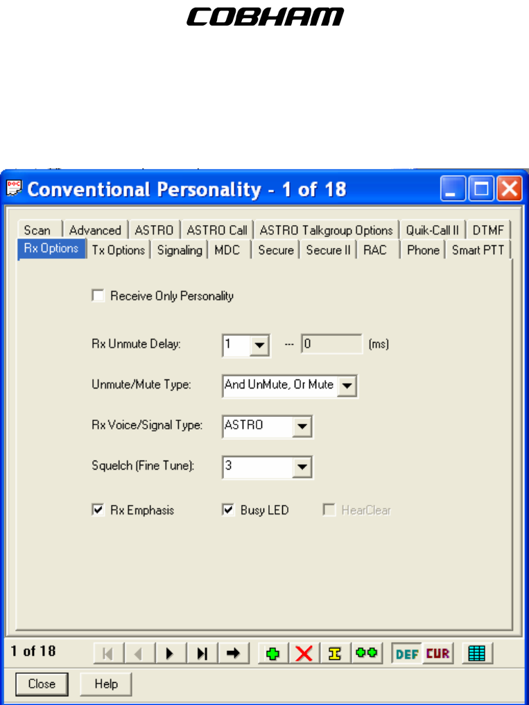
(1) RX Options – This menu allows you to modify the Conventional Personality’s RX settings.
The Receive Only Box allows the user to make the personality a Receive Only Personality.
Publication No. 150-041102 Page 52 of 88
Rev E C-5000 Operators Manual
FLEXCOMM I I
C-5000 ( P-25 Capable)
Operator’s Manual
This box is normally DISABLED. The user may also designate the RX Voice/Signal Type as
either ASTRO, Non-ASTRO, or Mixed Mode which will allow you to RX in both ASTRO and
Non-ASTRO mode. Utilize the Squelch (Fine Tune) to adjust the squelch level.
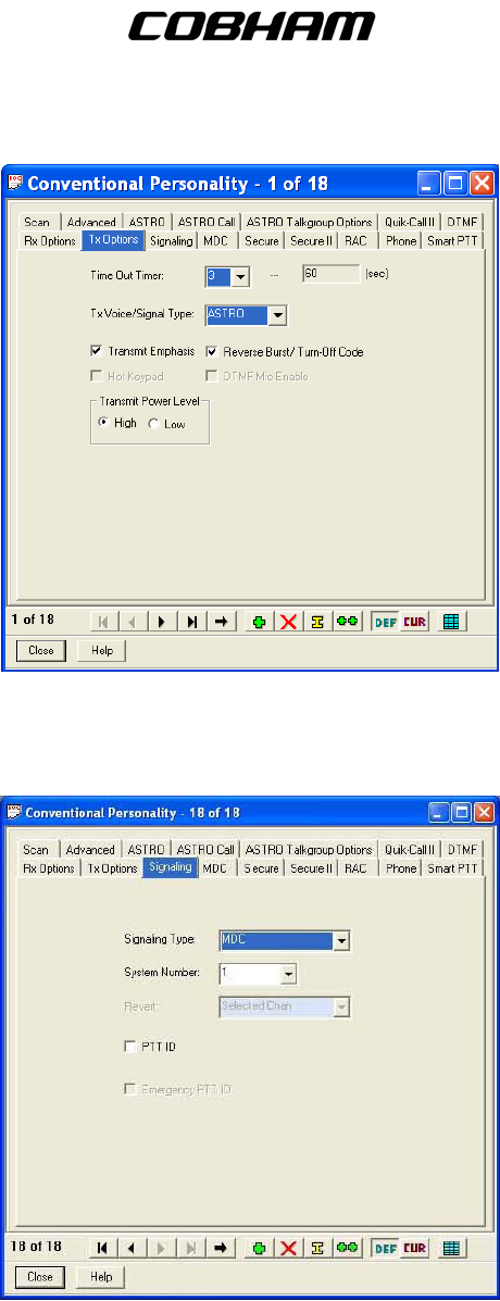
(2) TX Options – This menu allows you to modify the Conventional Personality’s TX settings.
The user may define the TX Voice/Signal Type as ASTRO or Non-ASTRO only if the RX
Voice/Signal Type was selected as Mixed Mode. The user may also select the Transmit
Power Level as either High or Low.
Publication No. 150-041102 Page 53 of 88
Rev E C-5000 Operators Manual
FLEXCOMM I I
C-5000 ( P-25 Capable)
Operator’s Manual
(3) Signaling - This menu allows you to modify the Conventional Personality’s Signaling
System. The Signaling Type may be None, MDC, Quick-Call II, or DTMF.
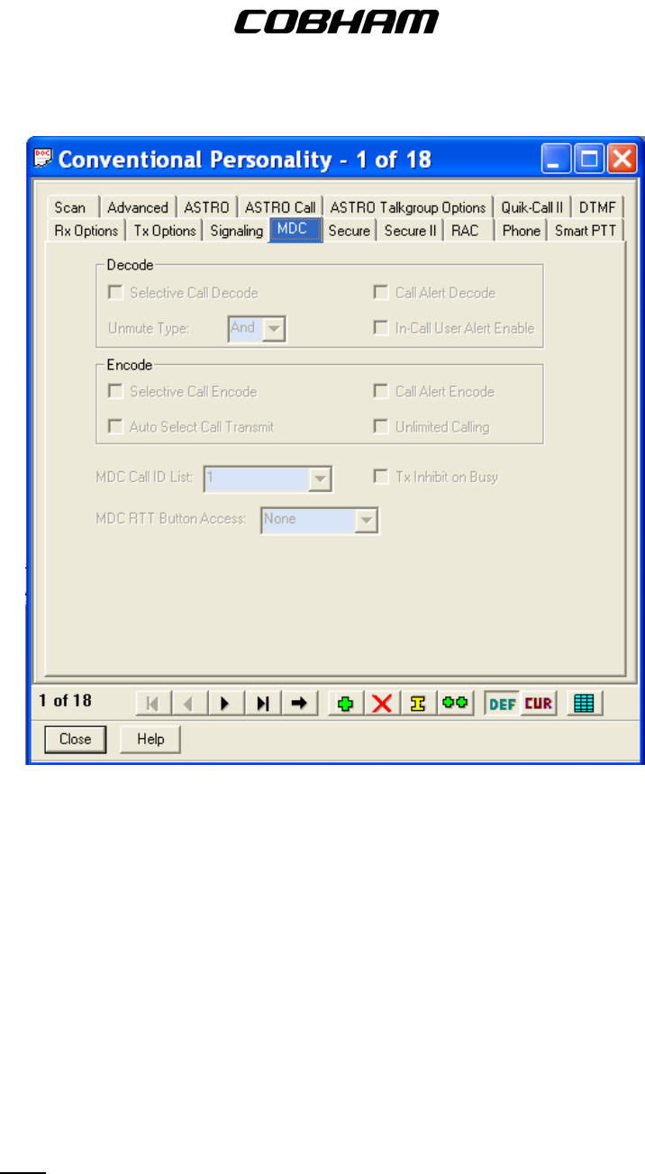
(4) MDC – This menu controls Selective Calling and Paging features of the radio, along with
control of the transmit function when other signals are present on the frequency. Please
note these options are only available if MDC is selected as the Signaling Type in the
Signaling menu. Leave all settings as shown below:
Publication No. 150-041102 Page 54 of 88
Rev E C-5000 Operators Manual
FLEXCOMM I I
C-5000 ( P-25 Capable)
Operator’s Manual
(5) Secure – This menu allow you to modify the Conventional Personality’s Secure options. The
user may select Clear or Secure in the Secure/Clear Strapping option and may select either
DES-XL, OTAR, or ASTRO OTAR.
(6) Secure II – This menu allows you to modify the Conventional Personality’s secure TX and
encoded RX operations. The user may select a key in the Voice Key Selection as well as
select Strapped in the Key Strapping option.
(7) RAC – This menu allows you to modify the Conventional Personality’s Repeater Access.
(8) Phone – This menu allow you to modify the Conventional Personality’s Phone code to use
the radio with a Phone System.
(9) Smart PTT – This feature is not enabled – Leave set to DISABLED.
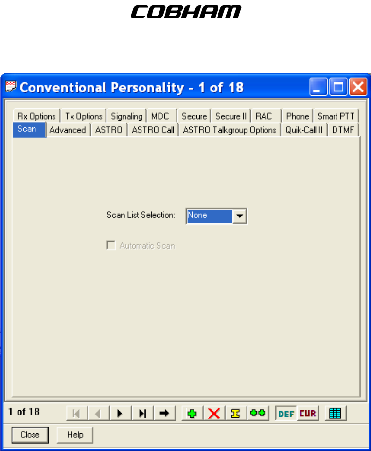
(10) Scan – This menu allows you to assign the Conventional Personalities to a Scan List. For
Vote scan operations users must select a valid scan list and ENABLE Automatic Scan.
Note: The Vote Scan feature is not available in all RT-5000 models.
Publication No. 150-041102 Page 55 of 88
Rev E C-5000 Operators Manual
FLEXCOMM I I
C-5000 ( P-25 Capable)
Operator’s Manual
(11) Advanced – This menu allows you to modify complex features of the Conventional
Personality. These options are left DISABLED.
(12) ASTRO – This menu allows you to modify the Conventional Personality’s ASTRO
parameters.
(13) ASTRO Call – This menu allows you to modify the Conventional Personality’s ASTRO
System functions.
(14) ASTRO Talkgroup Options – This menu allows you to modify the Conventional Personality’s
ASTRO System Talkgroup List functions.
(15) Quick-Call II – This menu allows you to modify the Call Alert and Selective Call parameters
for the Conventional Personality.
(16) DTMF – This menu allows you to modify the Call Alert tones for the Conventional Personality.
D. Message Alias List – This is used to configure various short messages to send via the radio.
This feature is currently not used in the FLEXCOMM System.
Publication No. 150-041102 Page 56 of 88
Rev E C-5000 Operators Manual
FLEXCOMM I I
C-5000 ( P-25 Capable)
Operator’s Manual
E. Status Alias List – This is used to configure various short status messages to send via the radio.
This feature is currently not used in the FLEXCOMM System.
F. MDC – This is used to configure the MDC operations of the radio.
(1) MDC Call List - This allows you to modify MDC call list menus.
(2) MDC Repeater ID List – This allows you to modify IDs for repeaters.
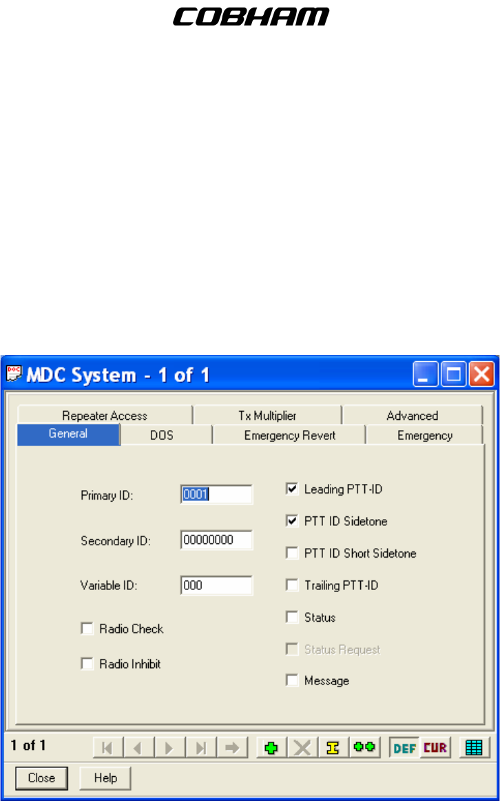
(3) MDC System – This menu controls the setup for MDC (Analog) operations. With the
exception of the Primary ID, the settings shown on this screen must remain as depicted.
The Primary ID is the Unique ID (UID) assigned to the radio, by radio serial number, when it
is first established in the radio network. No two radios may have the same UID.
(a) General - This menu allows the user to modify the General MDC system settings.
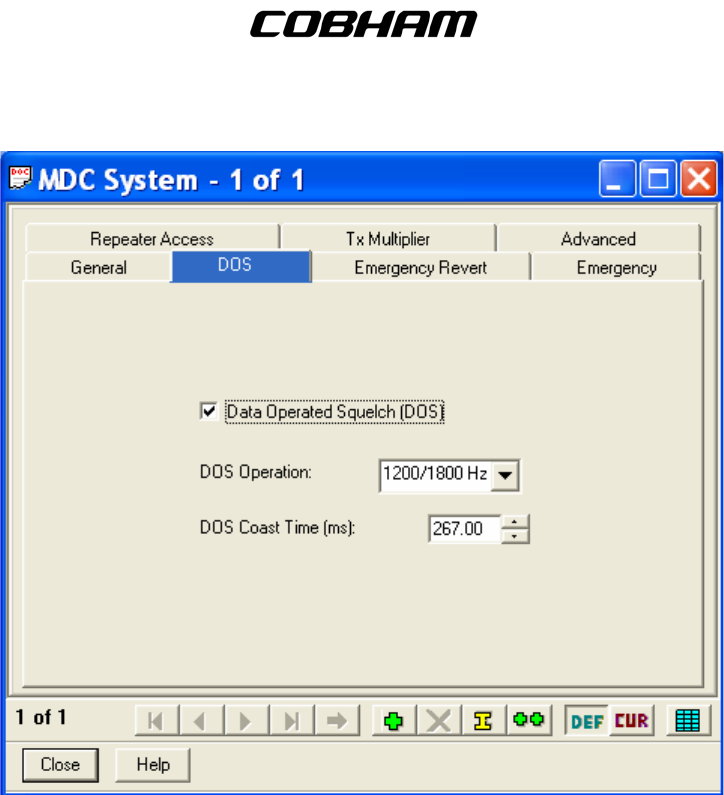
(b) DOS – This menu allows the user to modify the DOS settings for the MDC System.
Publication No. 150-041102 Page 57 of 88
Rev E C-5000 Operators Manual
FLEXCOMM I I
C-5000 ( P-25 Capable)
Operator’s Manual
(c) Emergency Revert – Allows the user to select a preset used to TX data in Emergency
Mode for the Conventional Personality. This menu is only available when Emergency
Enable is ENABLED in the Emergency Menu.
(d) Emergency – Allows the user to enable the Emergency Enable for the Conventional
Personality. Normally set to DISABLED.
(e) Repeater Access – Allows the user to enable Repeater function for the Conventional
Personality.
Pretime (ms): 200
(f) TX Multiplier – Allows the user to modify Emergency Mode key-up limits for the
Conventional Personality.
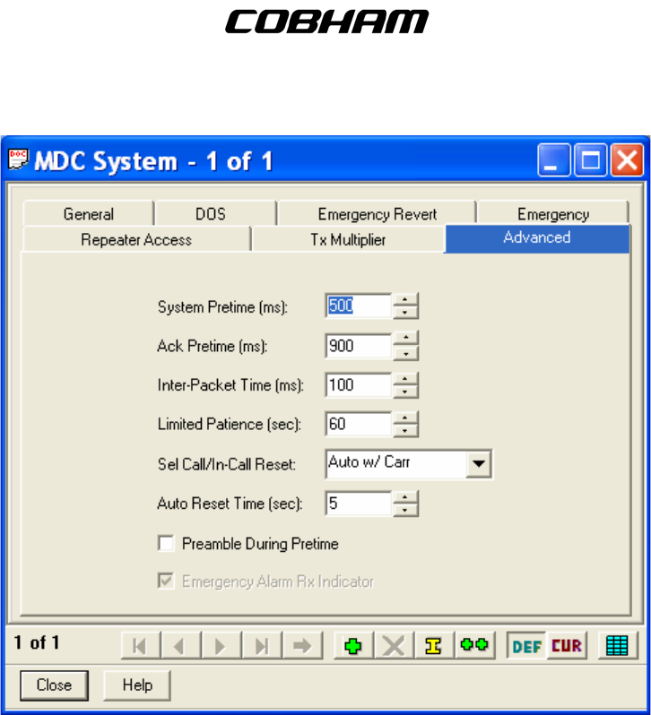
(g) Advanced – Allows the user to modify Advanced settings for the Conventional
Personality.
Publication No. 150-041102 Page 58 of 88
Rev E C-5000 Operators Manual
FLEXCOMM I I
C-5000 ( P-25 Capable)
Operator’s Manual
G. Quick-Call II – This is used to configure the Quick-Call II call alert and selective call for each
personality.
(1) Quick-Call II Call List – This allows you to select which Quick-Call II Call List to be used for
the Conventional Personalities.
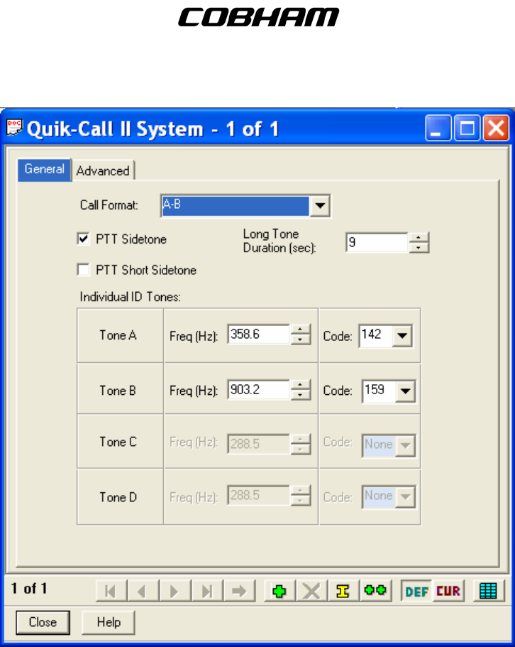
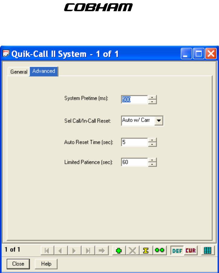
(2) Quick-Call II System – These menus allow you to modify the settings for the Quick-Call II
System.
(a) General – This menu allows you to modify the General settings of the Quick-Call II
System.
Publication No. 150-041102 Page 59 of 88
Rev E C-5000 Operators Manual
FLEXCOMM I I
C-5000 ( P-25 Capable)
Operator’s Manual
(b) Advanced - This menu allows you to modify the Advanced settings of the Quick-Call II
System.
Publication No. 150-041102 Page 60 of 88
Rev E C-5000 Operators Manual
FLEXCOMM I I
C-5000 ( P-25 Capable)
Operator’s Manual
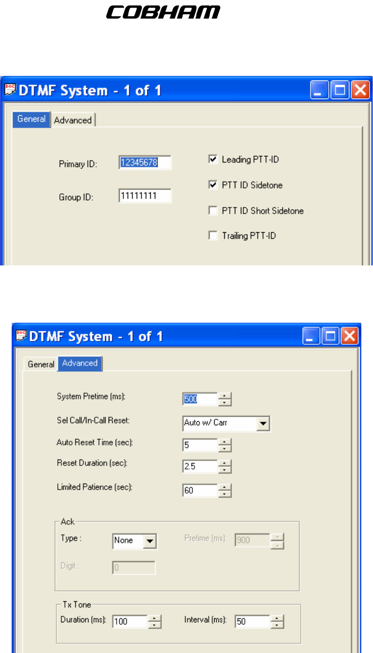
H. DTMF – This is used to configure the DTMF (Dual Tone Multiple Frequency) options.
(1) DTMF Call List – This allows you to select which DTMF Call List to be used for the
Conventional personalities.
(2) DTMF System – These menus allow you to modify the settings for the DTMF System.
(a) General – This menu allows you to modify the General settings of the DTMF System.
Publication No. 150-041102 Page 61 of 88
Rev E C-5000 Operators Manual
FLEXCOMM I I
C-5000 ( P-25 Capable)
Operator’s Manual
(b) Advanced – This menu allows you to modify the Advanced settings of the DTMF System.
I. Singletone – This is used to configure the Singletone frequency options.
Publication No. 150-041102 Page 62 of 88
Rev E C-5000 Operators Manual

FLEXCOMM I I
C-5000 ( P-25 Capable)
Operator’s Manual
(1) Singletone Frequency List – This allows you to select which Singletone Frequency is to be
used for the Conventional Personality repeater access. This is only available when the
Repeater Access Type is set to Singletone in the Conventional Personalities.
(2) Singletone System – These menus allow you to modify the settings for the Singletone
System.
PTT Sidetone: ENABLED
RAB Sidetone: ENABLED
Tone Pretime (ms): 250
Tone Duration (ms): 500
J. ASTRO Systems – This is used to configure the ASTRO system options for each personality.
(1) ASTRO Configuration – These menus allows the user to configure all aspects of ASTRO
operations for the radio.
(a) Radio Wide – This menu allows you to configure the Radio Wide ASTRO System
features:
Max TX Attempts: 4
Response Timer: 3300
Min Response Timer: 700
Max Packet Size: 512
(
b) Data – This menu allows you to modify the Data settings used for the ASTRO System.
Frame Sync Seek Period: 750
TX Short Random Range: 50
TX Long Random Range: 2000
TX Resp Random Range: 1000
TX Limited Patience: Infinite
(c) Group ID – This menu allows you to select the CAI (Common Air Interface) Group ID
number used for the ASTRO Systems.
NUM GROUP ID
1 10000000
2 10000000
3 10000000
4 10000000
5 10000000
6 10000000
7 10000000
8 10000000
(d) OTAC – This menu allows you to modify the OTAC (Over-The-Air-Channel) functions that
apply to all ASTRO Systems.
OTACS Feature: DISABLED
OTACR Feature: DISABLED
(e) OTAC Table – This menu allows you to modify the OTAC Table and assign the Zones
and Channels that utilize OTAC.
Publication No. 150-041102 Page 63 of 88
Rev E C-5000 Operators Manual
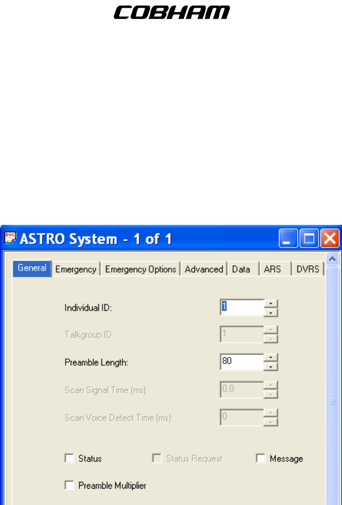
FLEXCOMM I I
C-5000 ( P-25 Capable)
Operator’s Manual
(f) Soft ID – This menu allows you to modify the Soft ID feature used whenever the PTT
button is pressed.
Soft ID Feature: ENABLED
(2) ASTRO System – These menus allow the user to modify the settings for ASTRO Digital
operations. All of the settings should remain as depicted EXCEPT the Individual ID. This is
the ASTRO ID assigned to the radio by serial number when it is first brought on line in the
radio network. It must be unique to the radio.
(a) General - This menu allows you to modify the General settings of the ASTRO System.
(b) Emergency – This menu allows you to modify the Emergency settings of the ASTRO
System.
Emergency: DISABLED
Emergency Type: Alarm Only
Acknowledge Alert Tone: Enabled
NUM REVERT ZONE REVERT CHANNEL
1 1 1
2 1 1
3 1 1
(c) Emergency Options – This menu allows you to modify the Emergency Options for the
ASTRO System.
Priority TX Inhibit: DISABLED
Publication No. 150-041102 Page 64 of 88
Rev E C-5000 Operators Manual
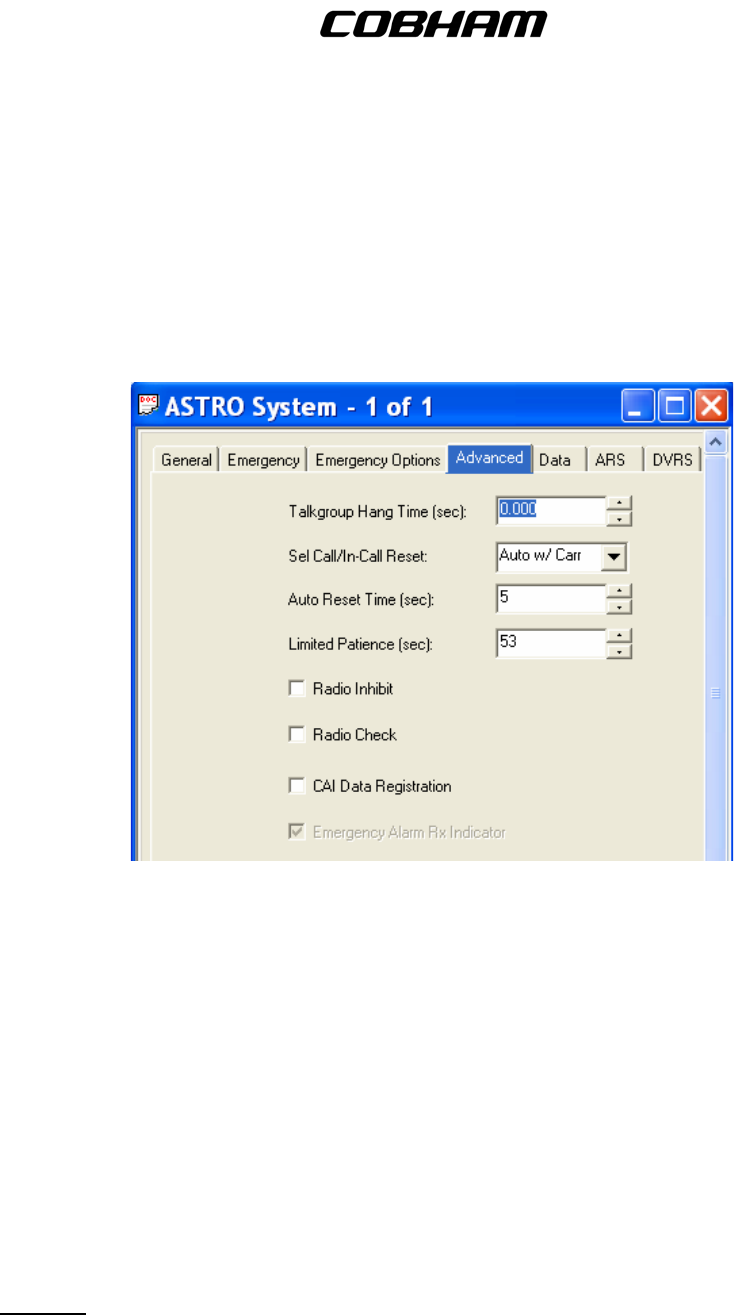
FLEXCOMM I I
C-5000 ( P-25 Capable)
Operator’s Manual
Limited Patience Time (sec): 0
Polite Retries: 5
Impolite Retries: 15
TX Multiplier: 0
Global TX Multiplier: DISABLED
Silent Override w/Mon: DISABLED
(d) Advanced – This menu allows you to modify the Advanced settings for the ASTRO
System.
(e) ARS – This menu allows you to modify the ARS (Automatic Registration Service)
settings.
Automatic Registration Service Enable: DISABLED
(f) DVRS – This menu allows you to modify the DVRS (Digital Vehicular Repeater System)
settings.
DVRS Operation Enable: DISABLED
(3) ASTRO Call List – This menu configures group and selective calling features. It is not
implemented and therefore should remain blank.
(4) ASTRO Talkgroups List –This entire menu is used to configure Conventional ASTRO mode
talkgroups, much like trunking. This feature is not supported at this time and therefore this
menu should remain empty. Any data shown on the menu is the factory default and may
remain.
10. Trunking – These menus contain elements that affect the configuration of the trunking system.
Publication No. 150-041102 Page 65 of 88
Rev E C-5000 Operators Manual
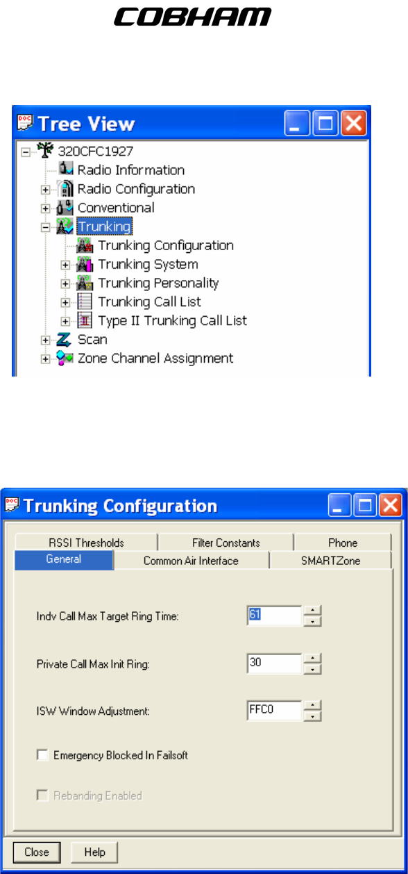
FLEXCOMM I I
C-5000 ( P-25 Capable)
Operator’s Manual
A. Trunking Configuration – This is used to configure the trunking system and all trunking
personalities.
(1) General – This menu allows you to modify the General options that apply to Trunking
Personalities.
(2) Common Air Interference – This menu allows you to change elements of the data sent
utilizing the CAI protocol.
Publication No. 150-041102 Page 66 of 88
Rev E C-5000 Operators Manual
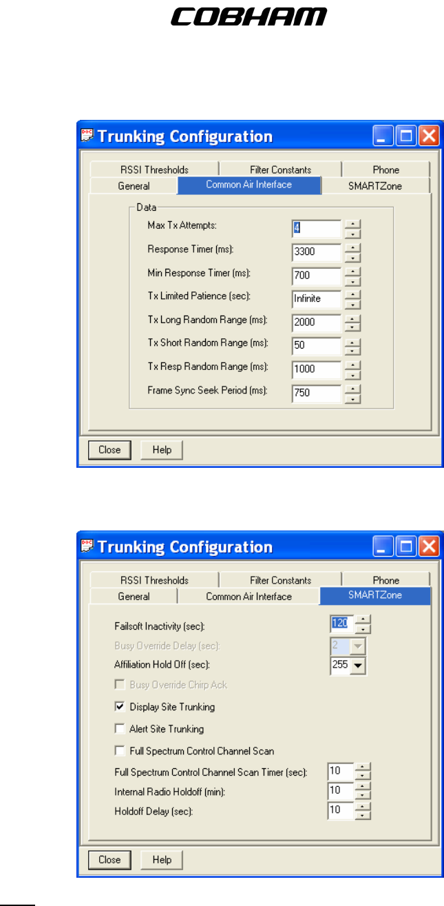
FLEXCOMM I I
C-5000 ( P-25 Capable)
Operator’s Manual
(3) SMARTZone – This menu allows you to modify elements of the SMARTZone functions that
can be utilized for all Trunking Personalities.
Note: Older Archive CPS files contained “Display Site Trunking” ENABLED. However this
must be DISABLED in order to function properly with customer trunking systems.
(4) RSSI Thersholds – This menu allows you to modify elements of the Received Signal Strength
Indication (RSSI) utilized for all Trunking Personalities.
Publication No. 150-041102 Page 67 of 88
Rev E C-5000 Operators Manual
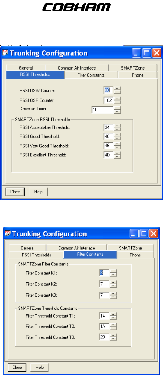
FLEXCOMM I I
C-5000 ( P-25 Capable)
Operator’s Manual
(5) Filter Constants – This menu allows you to modify Filter Constants used in conjunction with
the RSSI Thresholds that can be applied to all Trunking Personalities.
(6) Phone – This menu allows you to modify the Trunking Personality’s Phone Interconnect for
land-to-portable calls.
B. Trunking System – This is used to set-up the advanced options of the trunking system.
(1) ASTRO 25 Omnilink – This menu allows you to modify the Omnilink settings for ASTRO 25
mode.
Publication No. 150-041102 Page 68 of 88
Rev E C-5000 Operators Manual
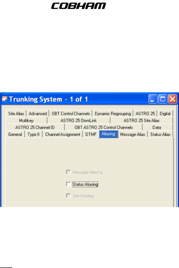
FLEXCOMM I I
C-5000 ( P-25 Capable)
Operator’s Manual
(a) General – This menu allows you to modify the General settings of the Trunking System.
(b) Type II – This menu allows you to modify the Type II Trunking Setting when Type II is
selected in the General menu.
(c) DTMF- This menu allows you to modify the DTMF settings for the Trunking System.
(d) Aliasing – This menu allows you to modify the Aliasing setting for the Trunking System.
(e) Message Alias – This menu allows you to modify the Message Aliasing settings for the
Trunking System.
(f) Status Alias – This menu allows you to modify the Status Aliasing settings for the
Trunking System.
(g) Site Alias – This menu allows you to modify the Site Aliasing settings for the Trunking
System.
Note: These fields should be set to DISABLED.
(h) Advanced – This menu allows you to modify the Advanced settings for the Trunking
System.
Publication No. 150-041102 Page 69 of 88
Rev E C-5000 Operators Manual
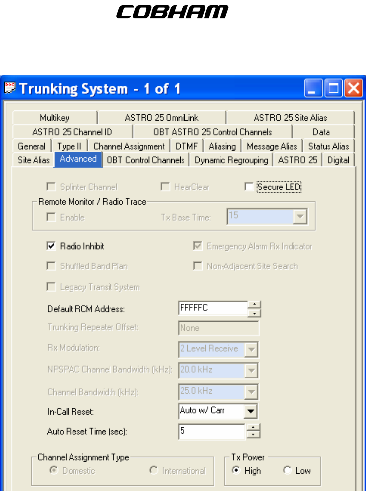
FLEXCOMM I I
C-5000 ( P-25 Capable)
Operator’s Manual
(i) ASTRO 25 Channel ID - This menu allows you to view the Channel ID settings for the
Trunking System.
(j) 700_800 ASTRO Control Channels – This menu allows you to modify the Control
Channel settings for the ASTRO 25 mode.
(k) Data – This menu allows you to modify the Data Settings for the Trunking System.
(l) ASTRO 25 Omnilink – This menu allows you to modify the Omnilink settings for ASTRO
25 mode.
(m) ASTRO 25 Site Alias – This menu allows you to modify the Site Alias settings for the
ASTRO 25 mode.
(n) 700_800 Control Channels – This menu allows you to modify the Control Channel
settings.
Publication No. 150-041102 Page 70 of 88
Rev E C-5000 Operators Manual
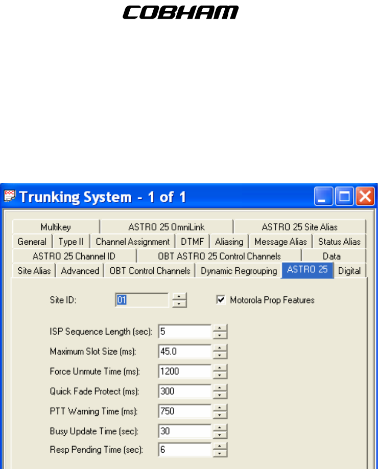
FLEXCOMM I I
C-5000 ( P-25 Capable)
Operator’s Manual
(o) Dynamic Regrouping – This menu allows you to modify the Dynamic Regrouping
settings.
Enable Dynamic Regrouping: DISABLED
(p) ASTRO 25 – This menu allows you to modify the ASTRO 25 settings for the Trunking
System.
(q) Digital – This menu allows you to modify the Digital settings used for digital
communications.
Publication No. 150-041102 Page 71 of 88
Rev E C-5000 Operators Manual
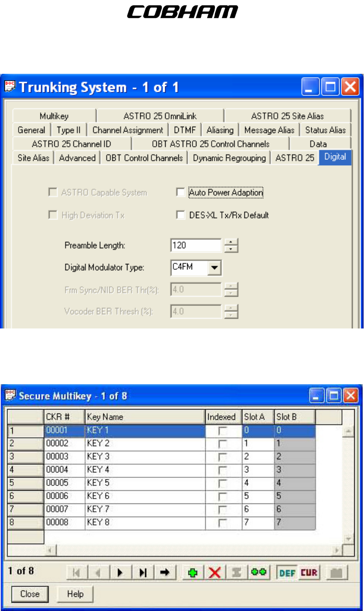
FLEXCOMM I I
C-5000 ( P-25 Capable)
Operator’s Manual
(r) Multikey- This menu allows you to assign Multikey fuctions.
C. Trunking Personality – This is used to set-up individual trunking personalities, as well as select
Type II or ASTRO 25 Trunking.
(1) General – This menu allows you to modify the General settings of the Trunking Personality.
Publication No. 150-041102 Page 72 of 88
Rev E C-5000 Operators Manual
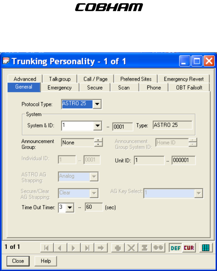
FLEXCOMM I I
C-5000 ( P-25 Capable)
Operator’s Manual
(2) Emergency - This menu allows you to modify the Emergency settings of the Trunking
Personality.
Publication No. 150-041102 Page 73 of 88
Rev E C-5000 Operators Manual
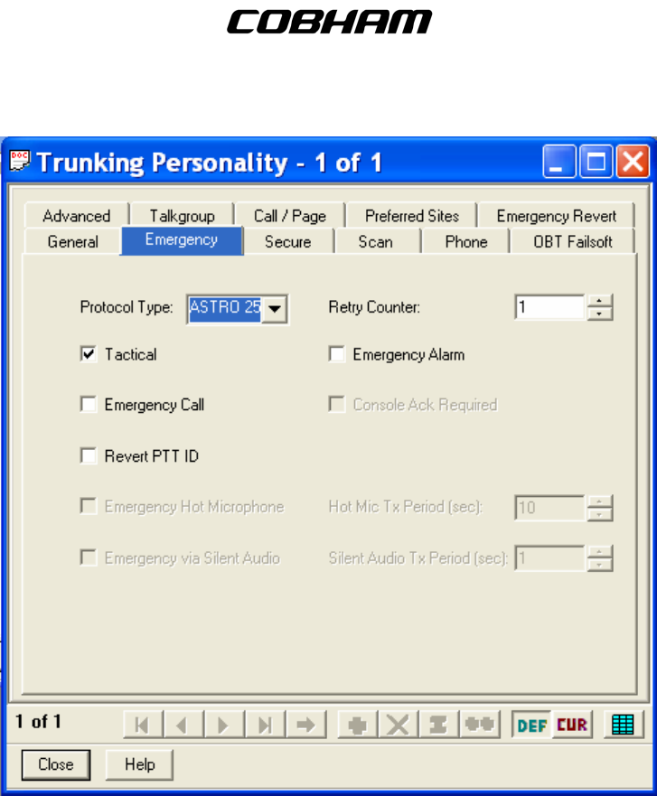
FLEXCOMM I I
C-5000 ( P-25 Capable)
Operator’s Manual
(3) Secure – This menu allows you to modify the Secure settings of the Trunking personality.
(4) Scan – This menu allows you to modify the Scan features of the Trunking Personality. Please
note that Scan is not currently available in the FLEXCOMM II System.
Scan List Selection: None
(5) Phone – This menu allows you to modify the Phone settings for the Trunking Personality.
Phone Interconnect: DISABLED
(6) 700/800 Failsoft – This menu allows you to modify the 700/800 Failsoft settings for the
Trunking Personality.
(7) Advanced – This menu allows you to modify the Advanced settings for the Trunking
Personality.
Publication No. 150-041102 Page 74 of 88
Rev E C-5000 Operators Manual
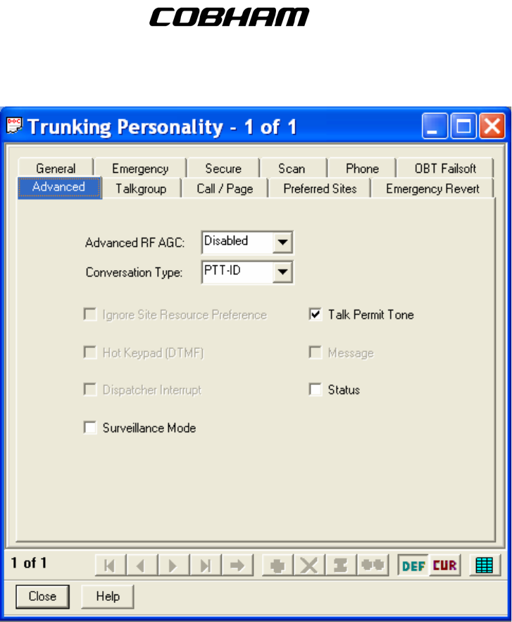
FLEXCOMM I I
C-5000 ( P-25 Capable)
Operator’s Manual
(8) Talkgroup – This menu allows you to select the Talkgroup for the Trunking Personality.
(9) Call/Page – This menu allows you to select the Call and Page Operation for the Trunking
Personality.
Publication No. 150-041102 Page 75 of 88
Rev E C-5000 Operators Manual
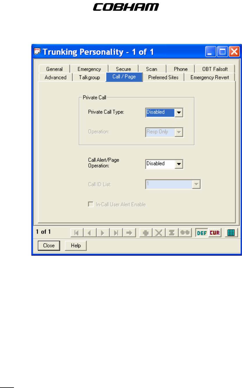
FLEXCOMM I I
C-5000 ( P-25 Capable)
Operator’s Manual
(10) Preferred Sites – This menu allows you to select the Preferred Sites for the Trunking
Personality.
(11) Emergency Revert – This menu allows you to modify and select the Emergency Revert
function for the Trunking Personality.
D. Trunking Call List – This is used to create trunking call lists.
E. Type II Trunking Call List – This is used as an advanced feature of the trunking system which
allows talkgroups to be set-up as trunking channels.
11. Scan – These menus contain elements that affect the scan mode. This feature is currently not used
in the FLEXCOMM System.
Publication No. 150-041102 Page 76 of 88
Rev E C-5000 Operators Manual
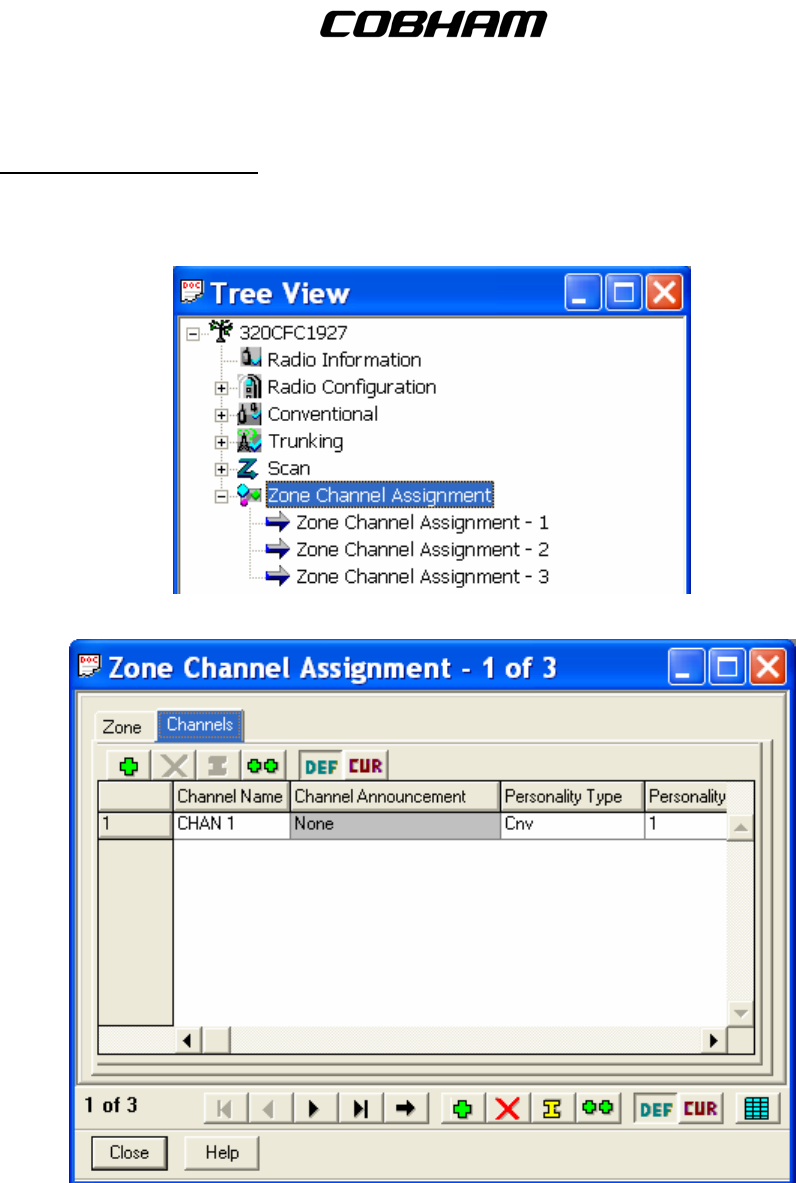
FLEXCOMM I I
C-5000 ( P-25 Capable)
Operator’s Manual
12. Zone Channel Assignment – These menus are used to assign any of the possible 255 Personalities
to a specific zone and channel, as well as enter the TX and RX frequencies, and assign the
Personality Type as either Conventional (Cnv) or Trunking (Trk). Please follow the CPS programming
notes outlined in Section 3 of this manual.
Publication No. 150-041102 Page 77 of 88
Rev E C-5000 Operators Manual

FLEXCOMM I I
C-5000 ( P-25 Capable)
Operator’s Manual
This page intentionally left blank.
Appendix A – CTCSS (PL) Tone Codes
Publication No. 150-041102 Page 78 of 88
Rev E C-5000 Operators Manual

FLEXCOMM I I
C-5000 ( P-25 Capable)
Operator’s Manual
C-5000
TONE
CODE
TONE
FREQ (HZ)
EIA
TONE
CODE
C-5000
TONE
CODE
TONE
FREQ (HZ)
EIA
TONE
CODE
01 67.0 XZ 35 179.9 6B
02 71.9 XA 36 186.2 7Z
03 74.4 WA 37 192.8 7A
04 77.0 XB 38 203.5 M1
05 79.7 SP 39 N/A N/A
06 82.5 YZ 40 N/A N/A
07 85.4 YA 41 210.7 M2
08 88.5 YB 42 218.1 M3
09 N/A N/A 43 225.7 M4
10 N/A N/A 44 233.6 M5
11 91.5 ZZ 45 241.8 M6
12 94.8 ZA 46 250.3 M7
13 97.4 ZB 47 229.1 9Z
14 100.0 1Z 48 150.0
15 103.5 1A 49 N/A N/A
16 107.2 1B 50 N/A N/A
17 110.9 2Z 51 69.3 WZ
18 114.8 2A 52 159.8
19 N/A N/A 53 165.5
20 N/A N/A 54 171.3
21 118.8 2B 55 177.3
22 123.0 3Z 56 183.5
23 127.3 3A 57 189.9
24 131.8 3B 58 196.6
25 136.5 4Z 59 N/A N/A
26 141.3 4A 60 N/A N/A
27 146.2 4B 61 199.5
28 151.4 5Z 62 206.5 8Z
29 N/A N/A 63 254.1 0Z
30 N/A N/A 64 Reserved
31 156.7 5A 65 Reserved
32 162.2 5B 66 Reserved
33 167.9 6Z 67 Reserved
34 173.8 6A 68 Reserved
Publication No. 150-041102 Page 79 of 88
Rev E C-5000 Operators Manual

FLEXCOMM I I
C-5000 ( P-25 Capable)
Operator’s Manual
This page intentionally left blank.
Publication No. 150-041102 Page 80 of 88
Rev E C-5000 Operators Manual

FLEXCOMM I I
C-5000 ( P-25 Capable)
Operator’s Manual
Appendix B – Mode 2 Operation
Overview
The C-5000 has the capability to control the RT-5000 in such a way that the user can monitor both the
main and the Guard (ITM) channel at the same time. This mode of operation is more difficult to use than
MODE 1.
The Home Page
The only visible difference in the HOME PAGE from Mode 1 operation is in the Main/Guard status fields.
The illustration below depicts the HOME PAGE for a system comprised of two digital RT-5000 radios.
Both radios are configured to operate in Mode 2. The Main transceiver is the active transceiver on radio
1. The digital transceiver (Guard) is the active transceiver on radio 2. The active transceiver is the one
that will transmit when the push-to-talk switch is depressed.
1 1 1 2 3 LUKEAFB T
W
R 1
2 2
. . 1 T A C T I C A L - 0 0 1
Guard Status Indicators
Main Status Indicators
Main/Guard Status Fields – These fields display symbols indicating the current status of all the
available transceivers in the system. The symbols are as follows.
. – Indicates a radio is available, but not enabled.
► – Indicates a radio is transmitting.
1 – Indicates Main/Guard 1 is available and enabled, but not active.
2 – Indicates Main/Guard 2 is available and enabled, but not active.
1 – Indicates Main/Guard 1 is available, enabled, and active.
2 – Indicates Main/Guard 2 is available, enabled, and active.
1 – Indicates Main/Guard 1 is receiving.
2 – Indicates Main/Guard 2 is receiving.
Publication No. 150-041102 Page 81 of 88
Rev E C-5000 Operators Manual

FLEXCOMM I I
C-5000 ( P-25 Capable)
Operator’s Manual
Setting the Active Transceiver
You can toggle the active transceiver for a radio between Main and Guard by pressing the soft keys. The
UPPER SOFT KEY toggles the active transceiver for radio 1. The LOWER SOFT KEY toggles the active
transceiver for radio 2. The following sequence of illustrations demonstrates this process for radio 1.
The Main transceiver is currently active.
1 1 1 2 3 LUKEAFB T
W
R 1
2 2
. . 1 T A C T I C A L - 0 0 1
Pressing the UPPER SOFT KEY makes the digital transceiver (Guard) active.
1 1 . 1 5 T A C T I C A L - 0 1 5
2 2
. . 1 T A C T I C A L - 0 0 1
Pressing the UPPER SOFT KEY again makes the Main transceiver active.
1 1 1 2 3 LUKEAFB T
W
R 1
2 2
. . 1 T A C T I C A L - 0 0 1
Selecting Preset Channels
Selecting preset channels in Mode 2 is conceptually the same as in Mode 1. If an MTM Guard receiver is
active, the user can only select preset channels programmed for an ITM, and the main transceiver will
only allow you to select channels programmed for a main transceiver. A ramification of this is that you
cannot select the manual channel while the Guard receiver is active.
Publication No. 150-041102 Page 82 of 88
Rev E C-5000 Operators Manual

FLEXCOMM I I
C-5000 ( P-25 Capable)
Operator’s Manual
Appendix C – Single Microphone Operation
Overview
Starting with software modification 11 (SWID 11), the C-5000 has the ability to control both radios with a
single microphone/headset. This feature, hereafter called single-mic mode, is useful for installations
where audio panel space is limited, or it is otherwise impractical to dedicate two ports to the C-5000.
The main features of single-mic mode are as follows:
Audio from all enabled sources are routed to the primary headset.
The operator can dynamically select which transceiver will be used for transmit.
Supports both Mode 1 and Mode 2 operation.
Configuring Single-Mic Mode
You can configure the C-5000’s microphone mode using either the Cobham Remote Programmer
software or from the C-5000’s front panel. To set the option using the Remote Programmer software,
simply select Single or Dual from the Mic Mode combo box, located on the Hardware Configuration
screen. To set the option from the C-5000’s front panel, simply select SINGLE or DUAL from the option
list on the MIC MODE configuration page. This page, depicted below, is located under the SETUP MISC.
sub-menu of the CFG SYSTEM menu.
S E T U P : 2=NEXT 3=B A C K
M I C MODE -SI N G L E
The Home Page
The main visible difference in single-mic mode is the addition of the active RT indicator, displayed as an
unfilled triangle. The active RT indicator shows which RT will be used for transmit. The illustration below
depicts the HOME PAGE for a system comprised of two digital RT-5000 radios. Both radios are
configured to operate in Mode 2. The Main transceiver of radio 1 is the both the active transceiver for
radio 1 and the active RT for the entire system. The digital transceiver (Guard) is the active transceiver
on radio 2.
1 1 2 3 LUKEAFB T W R 1
2 2
. . 1 TACTICAL- 0 0 1
Guard Status Indicators
Main Status Indicators
Publication No. 150-041102 Page 83 of 88
Rev E C-5000 Operators Manual
FLEXCOMM I I
C-5000 ( P-25 Capable)
Operator’s Manual
Setting the Active RT
You can change the active RT by pressing the soft keys. If radio 1 does not already contain the active
RT, pressing the UPPER SOFT key will make radio 1’s active transceiver the active RT. If radio 1 already
contains the active RT, pressing the UPPER SOFT key toggles the active RT between radio 1’s Main and
Guard. The LOWER SOFT key performs the same operations for radio 2. The following sequence of
illustrations demonstrates changing the active RT using the soft keys.
The Guard transceiver of radio 2 is currently the active RT.
1 1 1 2 3 LUKEAFB T W R 1
2
. . 1 TACTICAL- 0 0 1
Pressing the UPPER SOFT key makes the Main transceiver of radio 1 the active RT.
1 1 2 3 LUKEAFB T W R 1
2 2
. . 1 TACTICAL- 0 0 1
Pressing the UPPER SOFT key again makes the Guard transceiver of radio 1 the active RT.
1 . 1 5 TACTICAL- 0 1 5
2 2
. . 1 TACTICAL- 0 0 1
Pressing the UPPER SOFT key again makes the Main transceiver of radio 1 the active RT.
1 1 2 3 LUKEAFB T W R 1
2 2
. . 1 TACTICAL- 0 0 1
Pressing the LOWER SOFT key makes the Guard transceiver of radio 2 the active RT.
1 1 1 2 3 LUKEAFB T W R 1
2
. . 1 TACTICAL- 0 0 1
Pressing the LOWER SOFT key again makes the Main transceiver of radio 2 the active RT.
1 1 1 2 3 LUKEAFB T W R 1
2
. . 1 TACTICAL- 0 0 1
Publication No. 150-041102 Page 84 of 88
Rev E C-5000 Operators Manual
FLEXCOMM I I
C-5000 ( P-25 Capable)
Operator’s Manual
Muting Inactive Receivers
The C-5000 can be configured such that the DIM key invokes the MUTE function rather than the DIM
function. When MUTE is active, the audio from all non-active transceivers will be muted. Muted
transceivers are indicated by an ‘M’ character in their status fields. See depiction below.
M
. 1 5 T A C T I C A L - 0 1 5
M .
. . 1 T A C T I C A L - 0 0 1
You can configure the DIM key for the MUTE function using either the Cobham Remote Programmer
software or from the C-5000’s front panel. To set the option using the Remote Programmer software,
simply select DIM or MUTE from the DIM Key Mode combo box, located on the Hardware Configuration
screen. To set the option from the C-5000’s front panel, simply select DIM or MUTE from the option list
on the DIM KEY MODE configuration page. This page, depicted below, is located under the SETUP
MISC. sub-menu of the CFG SYSTEM menu.
S E T U P : 2=NEXT 3=B A C K
D I M K E Y MODE -MUT E
Publication No. 150-041102 Page 85 of 88
Rev E C-5000 Operators Manual

FLEXCOMM I I
C-5000 ( P-25 Capable)
Operator’s Manual
This page intentionally left blank.
Publication No. 150-041102 Page 86 of 88
Rev E C-5000 Operators Manual

FLEXCOMM I I
C-5000 ( P-25 Capable)
Operator’s Manual
Appendix D – Equivalent Part Numbers
Because RT-5000’s and C-5000’s are maintained as separate products, there can be circumstances
when a new flavor (part number) of RT-5000 is released, but the C-5000 is not yet aware of its existence.
This problem manifests itself as rejected part numbers in the C-5000 configuration pages for RT-5000
radios. Should this occur, the work around is to enter an RT-5000 part number that will make the C-5000
function properly for the intended radio. As far as the C-5000 is concerned, only the module and
encryption types are significant.
Should your RT-5000 part number be rejected by the C-5000, find an RT-5000 part number (last 4 digits)
in the table that has the equivalent part number to the RT-5000 you are trying to configure. Enter the
equivalent part number into the C-5000 configuration pages, and your RT-5000 should function properly.
Standard RT-5000 Alternative RT-5000 Part Numbers
-0101 -0101
-0201 -0201
-0301 -0301
-0401 -0401
-0501 -0501
-0611 -0611
-0711 -0711
-0811 -0811
-0911 -0911
-1011 -1011
-1111 -1111
-1211 -1211
-1311 -1311
-1411 -1411
-1511 -1511
-1611 -1611
-1711 -1711
-1811 -1811
-1911 -1911
-2011 -2011
-2111 -2111
-2211 -2211
-2311 -2311
-2411 -2411
-2511 -2511
-2611 -1011
-2711 -1211
-2811 -0611
-2911 -0611
-3011 -1211
-3111 -1311
-3211 -0811
-3311 -0611
-3411 -2111
-3511 -2411
-5011 -1611
-5111 -2411
-5211 -2011
-5311 -1211
continues..........
Publication No. 150-041102 Page 87 of 88
Rev E C-5000 Operators Manual

FLEXCOMM I I
C-5000 ( P-25 Capable)
Operator’s Manual
Publication No. 150-041102 Page 88 of 88
Rev E C-5000 Operators Manual
Appendix D – Equivalent Part Numbers (cont’d)
-5411 -0811
-5511 -1011
-5611 -0611
-5711 -2611
-5811 -0611
-5911 -0611
-6011 -2411
-6111 -6111