Wulfsberg Electronics Division RT-5000P-11 29.7 to 960 MHz Tactical Airborne Transceiver User Manual REV
Wulfsberg Electronics Division 29.7 to 960 MHz Tactical Airborne Transceiver REV
UserManual.wiki
>
Wulfsberg Electronics Division
>
RT 5000P 11 User Manual
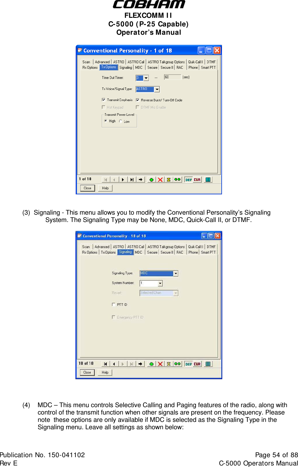
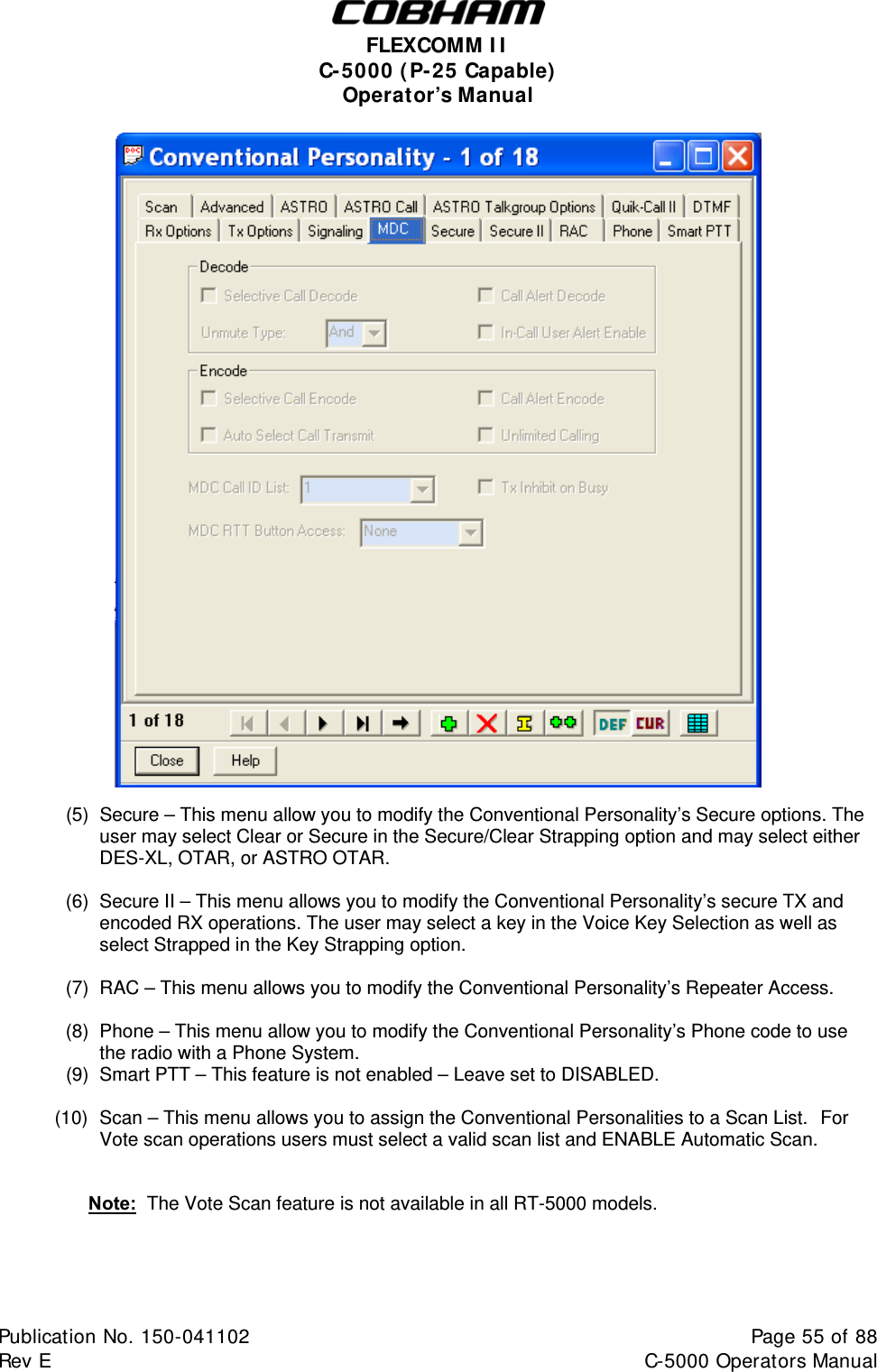
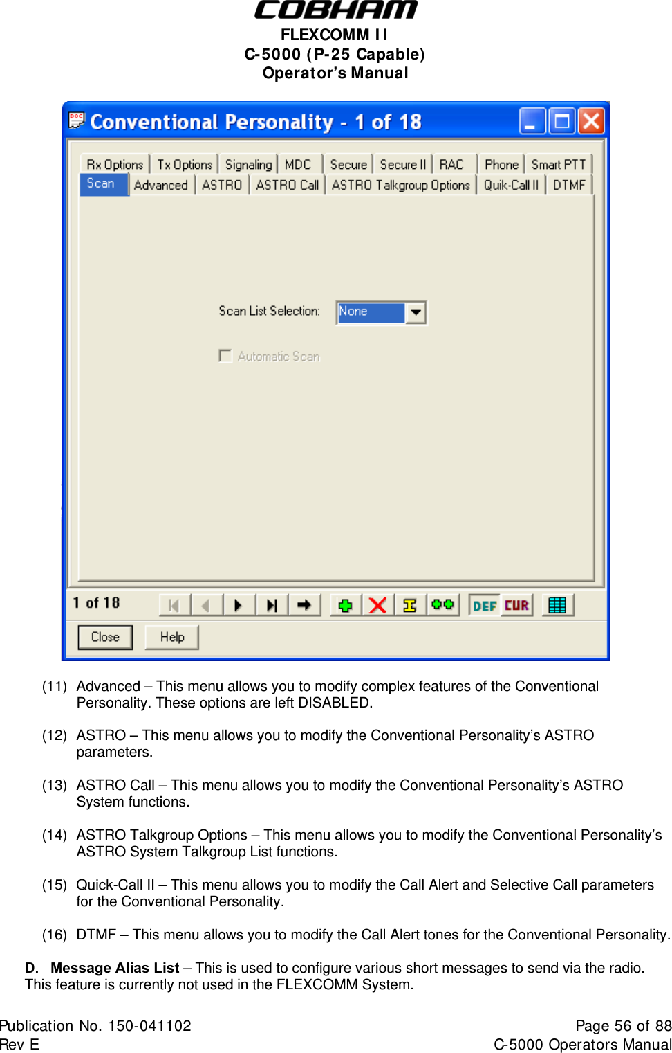
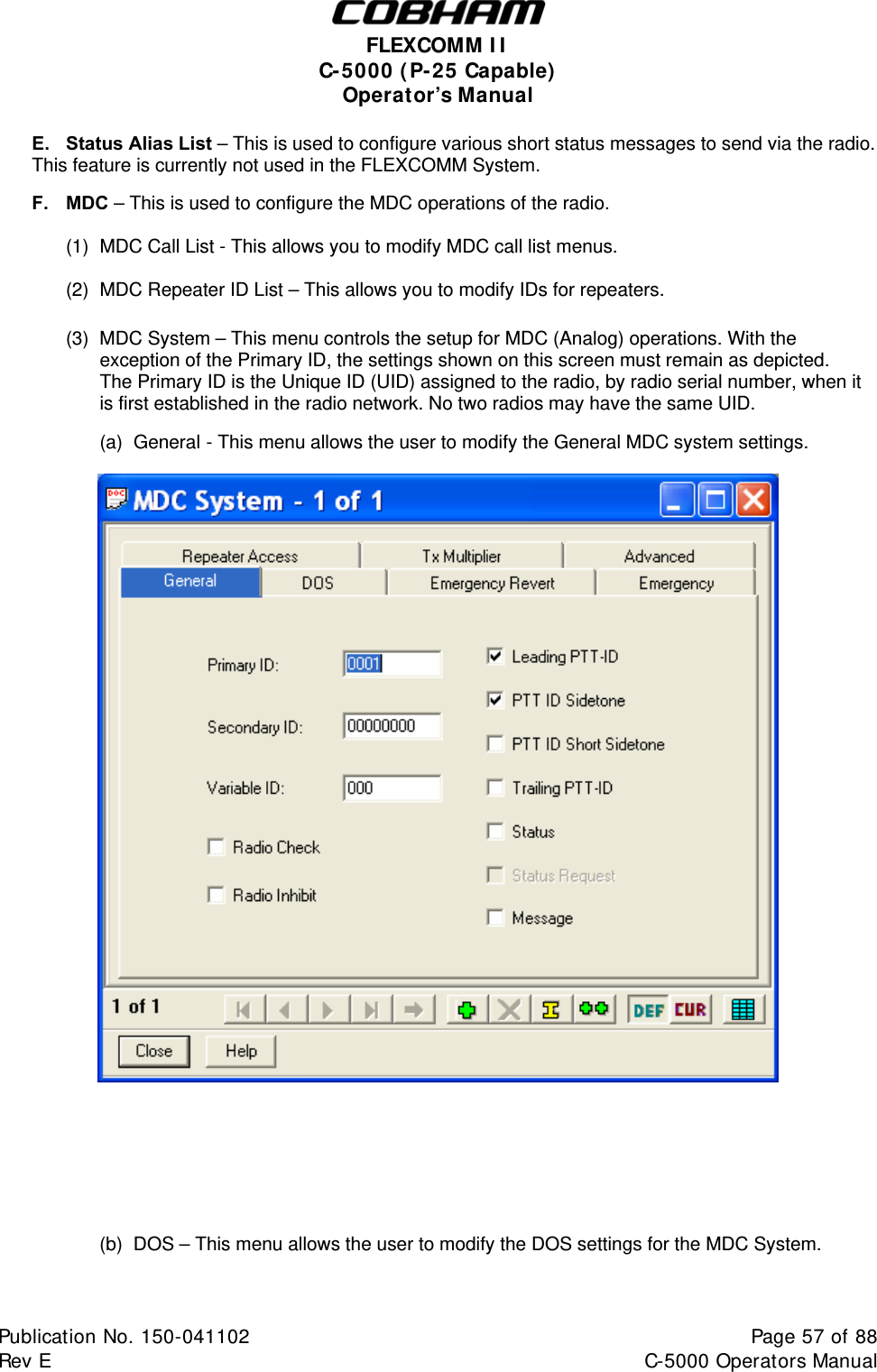
User's Manual
Navigation menu
Upload a User Manual
Namespaces
Wiki Guide
HTML
PDF
Info
Views
User Manual
Discussion / Help
Navigation