Wulfsberg Electronics Division VC-401B VHF ATC Communication Transceiver for aircraft ins User Manual pilot guide
Wulfsberg Electronics Division VHF ATC Communication Transceiver for aircraft ins pilot guide
UserManual.wiki
>
Wulfsberg Electronics Division
>
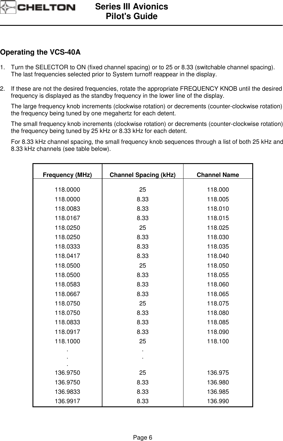
VC 401B User Manual
pilot guide
Navigation menu
Upload a User Manual
Namespaces
Wiki Guide
HTML
PDF
Info
Views
User Manual
Discussion / Help
Navigation