Wyse Technology WT8440 Windows-Based Terminal User Manual
Wyse Technology Windows-Based Terminal Users Manual
UserManual.wiki
>
Wyse Technology
>
WT8440 User Manual
>
User Manual
Contents
1.
User Manual
2.
Special Accessories Instruction
3.
Revised User Manual
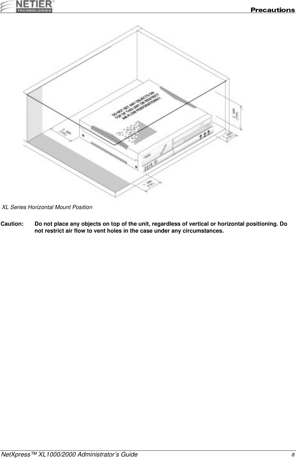
User Manual
Navigation menu
Upload a User Manual
Namespaces
Wiki Guide
HTML
PDF
Info
Views
User Manual
Discussion / Help
Navigation
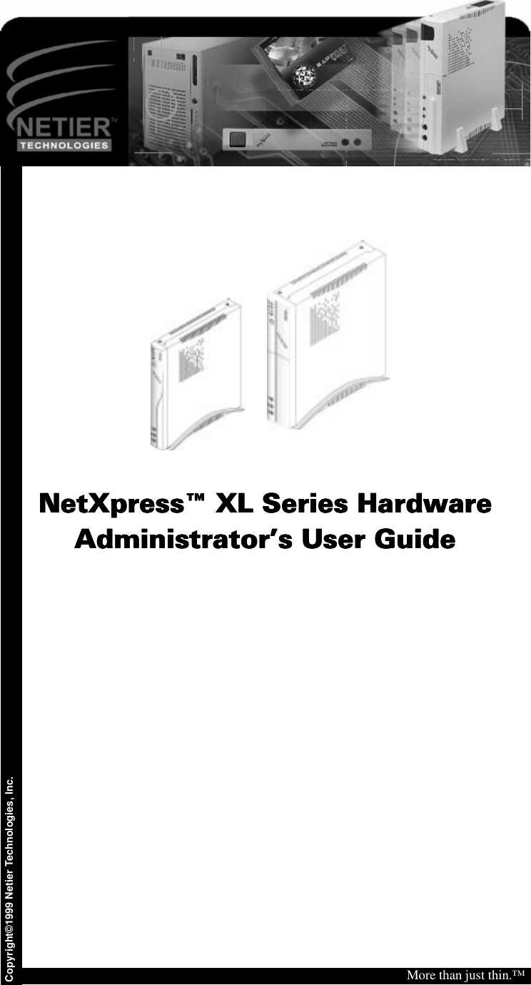
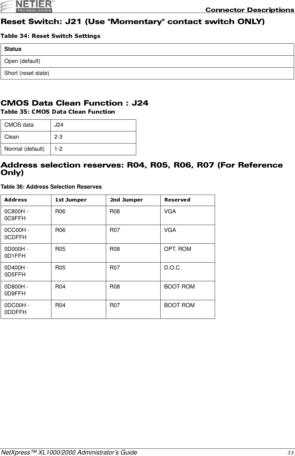
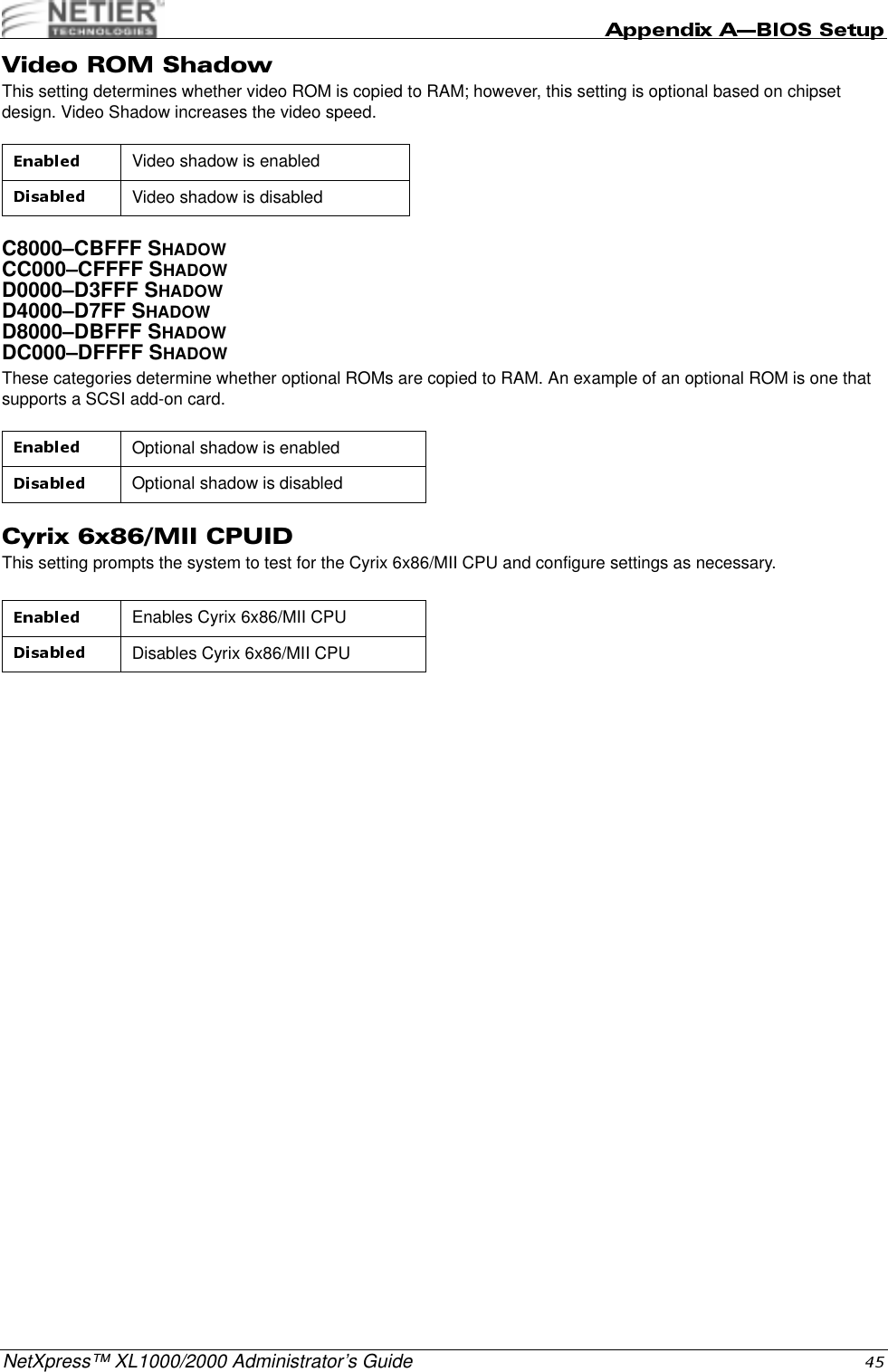
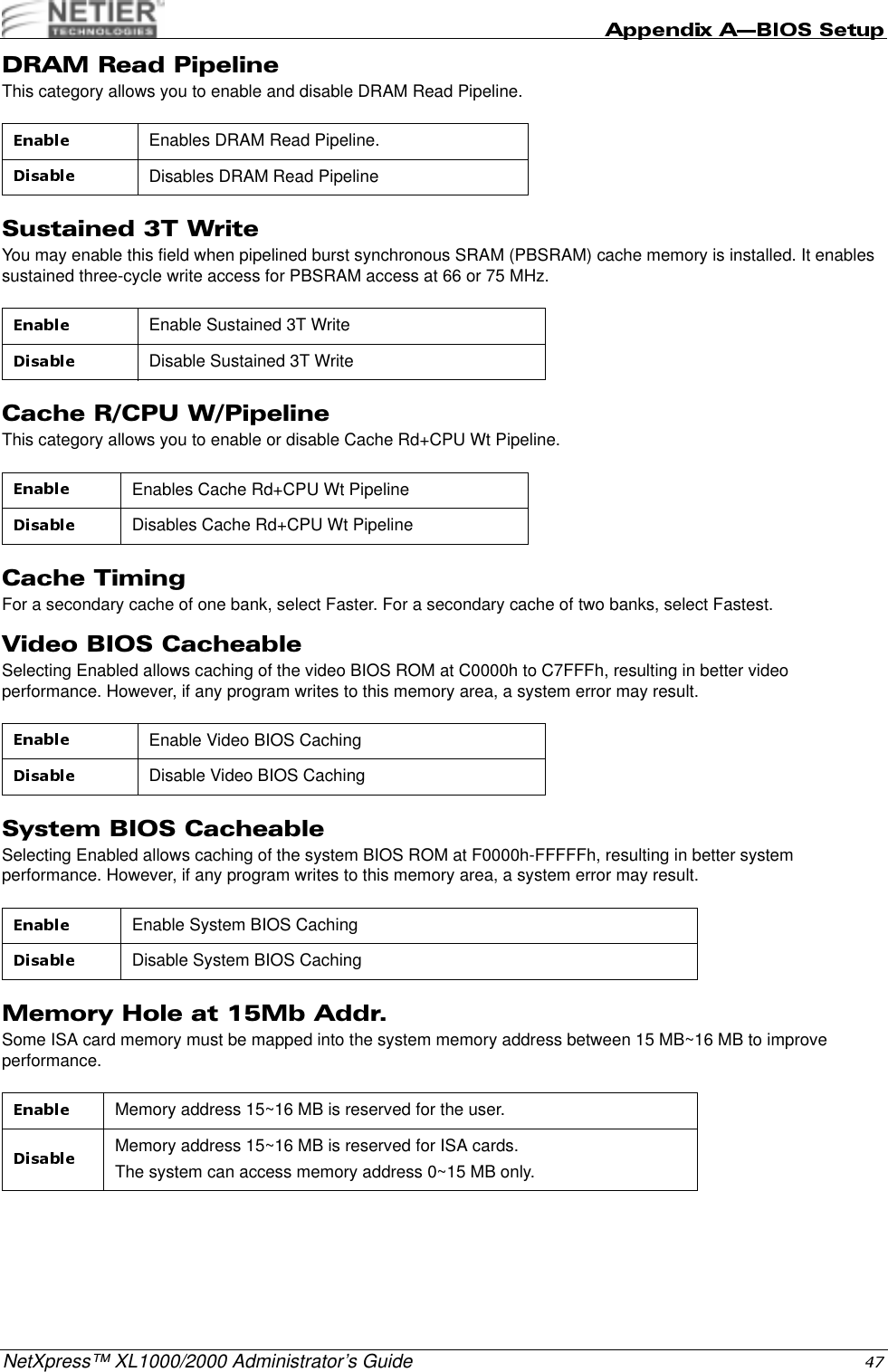
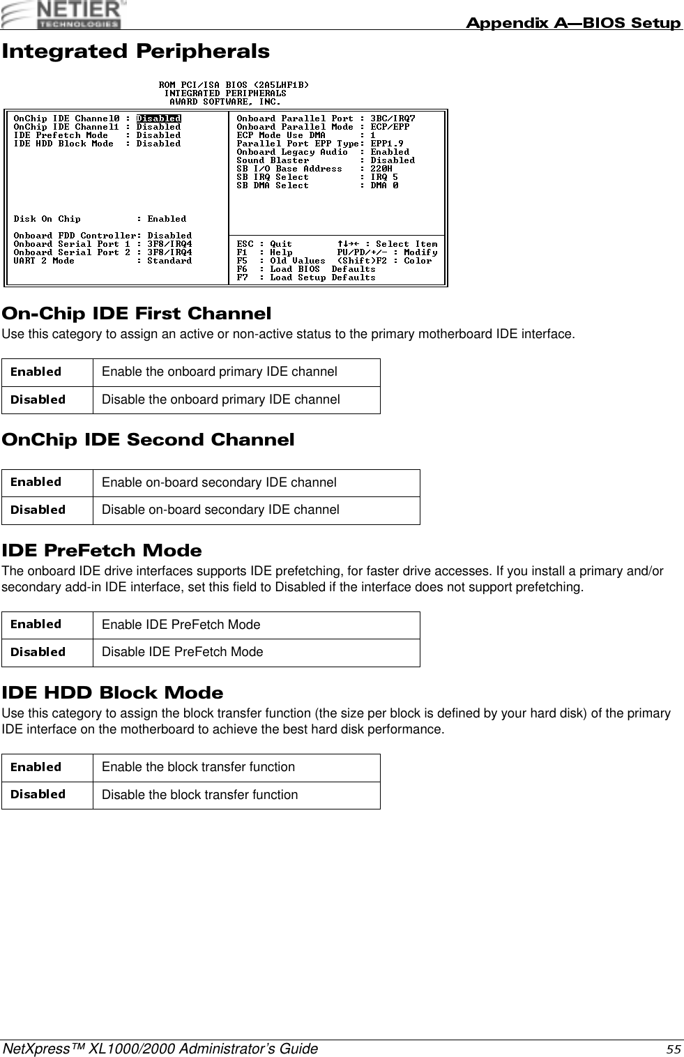
![NetXpress™ XL1000/2000 Administrator’s GuideThese specifications are subject to change without notice. !"1 x Mini-DIN connector for PS/2 mouseCPU temperature monitoringCPU core, system power voltage detectionRealtek RTL-8139B(F)100Base-TX/10Base-T Ethernet with PCI master interfaceSupport for Wake On LANSupport for Pre-boot eXecution Environment (PXE) functionM-Systems DOC2000 socket x 1 (32-pin DIP JEDEC standard)M-Systems DIM2000 socket x 1 (144-pin SoDIMM future option) Compact Flash daughter card w/ejector (option)Switching voltage regulator on-board for full range processor voltage requirements.Operating Temperature range:Non-operating temperature range:32 °F~104 °F (0 °C~40 °C) [With heat sink and fan]-14 °F~140 °F (-10 °C~60 °C)Board Physical W x D x H (overall) = 230mm (9-1/8") x 207mm (8-1/8") x 1.3mm (0.051")CPU ZIF Socket-7/Super Socket-7 supportMain Memory 2 x 168-pin DIMM socketsL2 Cache 512KB on-boardFlash File System 1 x 32-pin DIP JEDEC standard socket144-pin SoDIMM (future option)Compact Flash 1 x IDE compact flash ejector header (optional)- Selectable as master or slave driveExpansion Bus 1 x PCI/ISA Riser card support(XL 2000)Primary IDE header 1 x 44-pin 1mm pitch headerSerial port 1 x 9-pin D-SUB RS232 FIFO (16550 compatible) Serial port connectorParallel port 1 x 25-pin D-SUB Parallel port (SPP/EPP/ECP) connectorUSB ports 2 x USB connectors/stackedSVGA port 1 x 15-pin High Density D-SUB Audio ports 1 Microphone Input1 Stereo Audio Output1 Stereo Audio InputKeyboard port 1 PS/2 style keyboard portMouse port 1 PS/2 style mouse portPower 1 (8-pin) DC power input supporting external ATX power supplyPower Switch 1 Momentary "Soft" power switch. Bezel mounted ON/OFF/SUSPEND](https://usermanual.wiki/Wyse-Technology/WT8440.User-Manual/User-Guide-165067-Page-17.png)
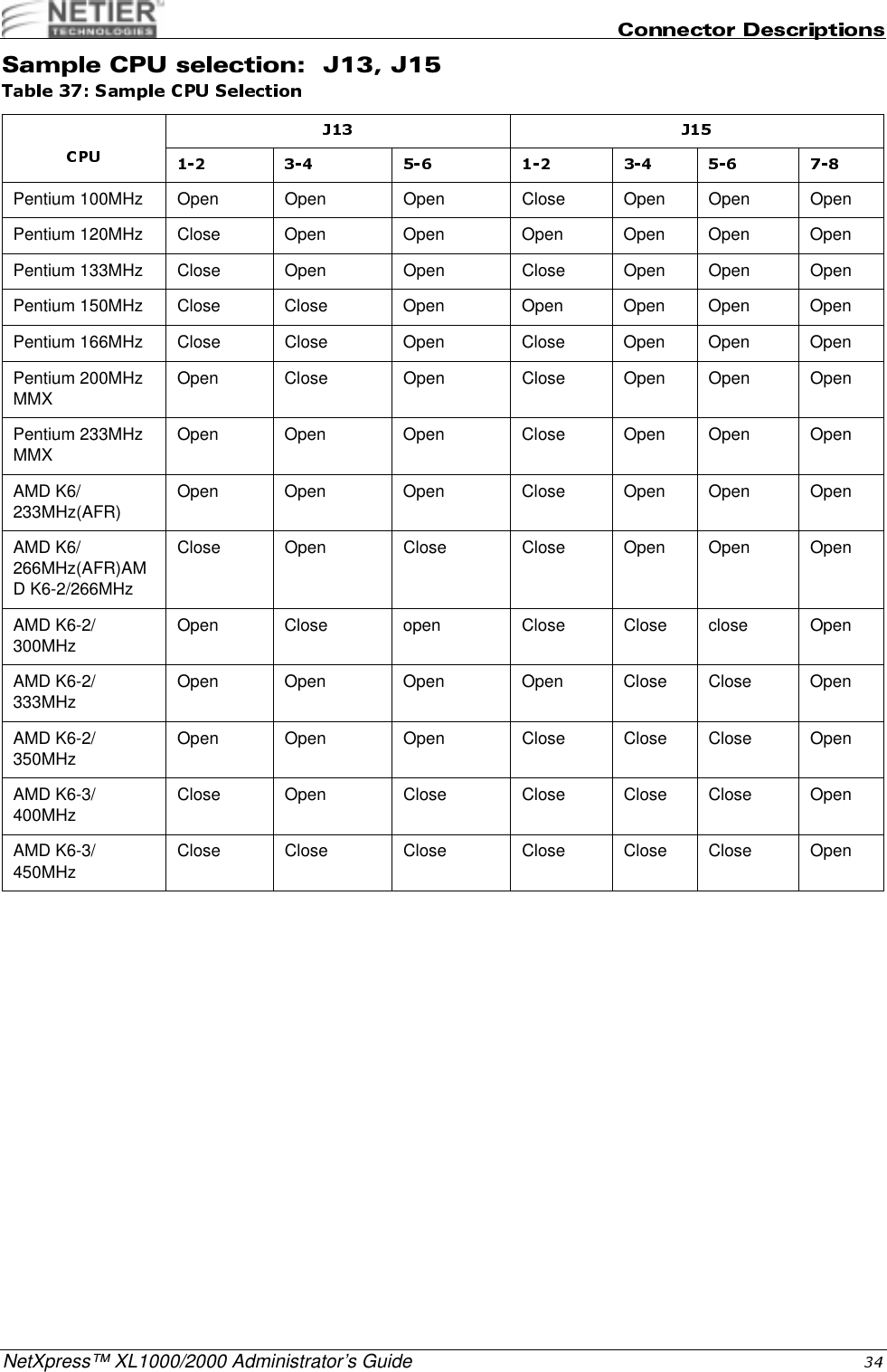
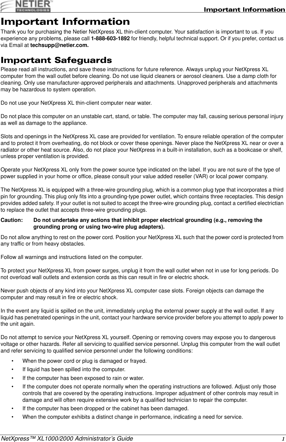
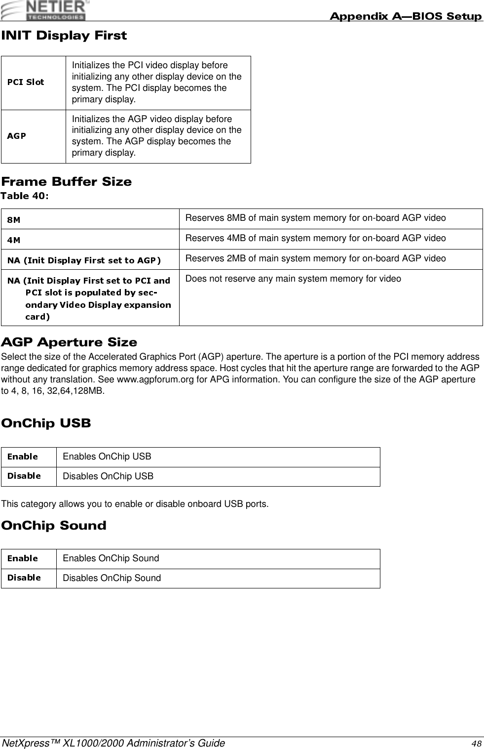
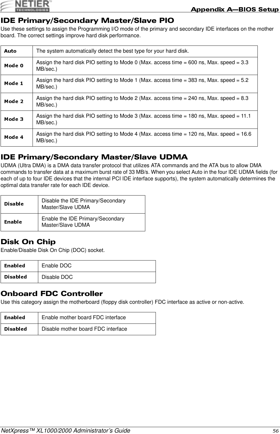
![NetXpress™ XL1000/2000 Administrator’s Guide.A description of the selected (highlighted) setup function appears on the bottom of the screen.&Press F1 to display a small pop-up help window that describes the setup control key functions and possible uses for each key. Press F1 or Esc to exit the Help window.F2/[Shift]+F2 Change color from a total of 16 colors.F2 to select color forward, [Shift] F2 to select color backwardF3 ReservedF4 ReservedF5 Restore the previous CMOS value from CMOS; only for Option Page Setup MenuF6 Load the default CMOS value from the BIOS default table; only for Option Page Setup MenuF7 Load the Setup default; only for Option Page Setup MenuF8 ReservedF9 ReservedF10 Save all CMOS changes; only for Main Menu](https://usermanual.wiki/Wyse-Technology/WT8440.User-Manual/User-Guide-165067-Page-38.png)
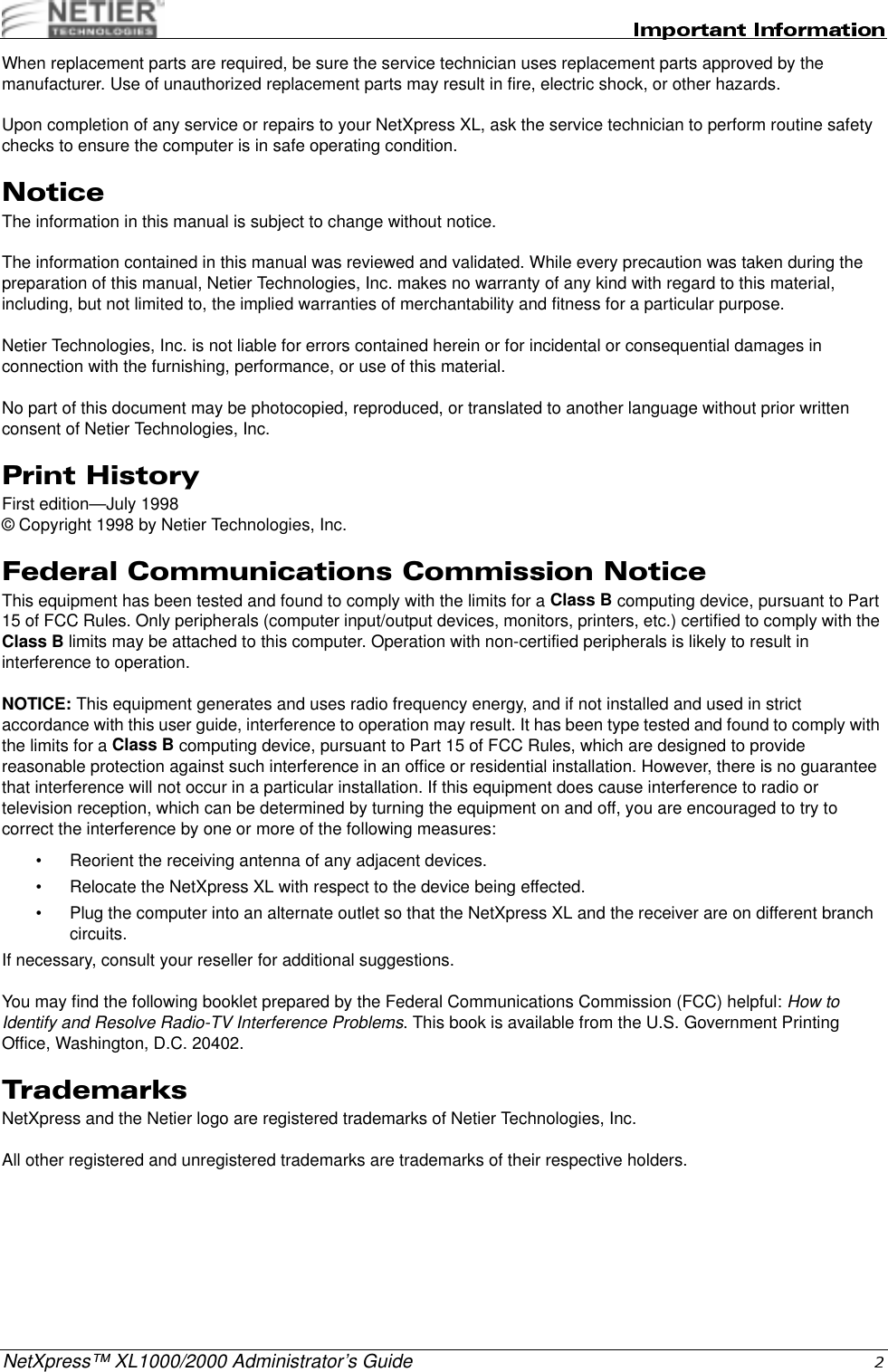
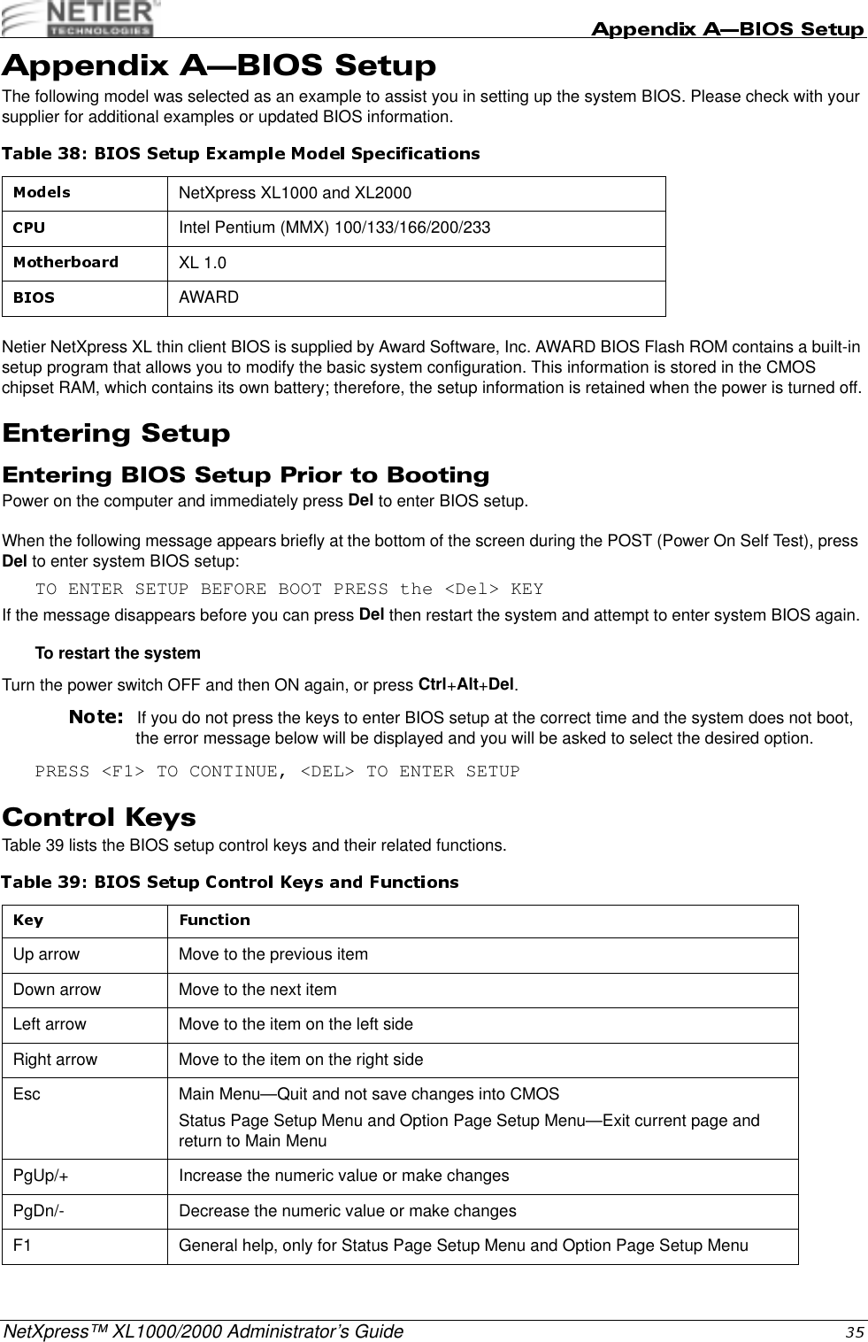
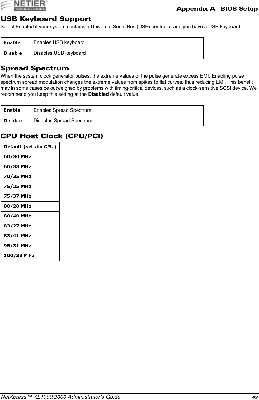
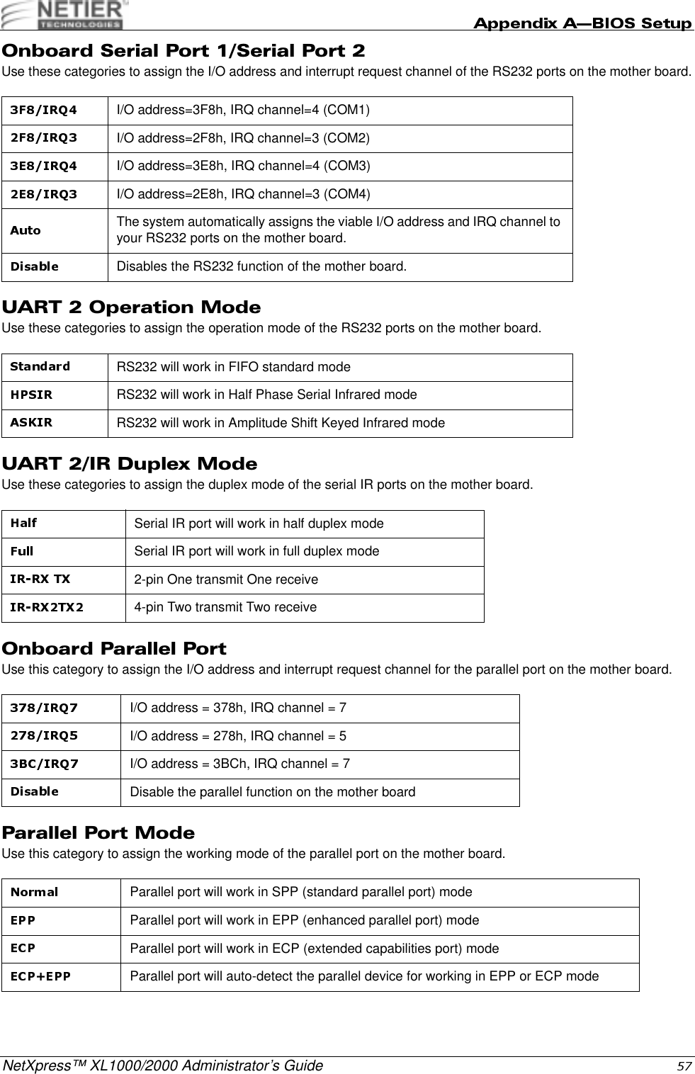
![NetXpress™ XL1000/2000 Administrator’s GuideUse the IDE HDD Auto Detection function to automatically detect and configure hard disk parameters. See “IDE HDD Auto Detection” on page 59 for details.<009"This function is the hard disk low level format utility. See “Hard Disk Low Level Format Utility” on page 62 for details."!>Choose this function to save CMOS value changes and exit setup.!>3"Choose this function to abandon all CMOS value changes and exit setup.#$#The items in the Standard CMOS Setup Menu are divided into 11 categories. Each category includes zero, one, or more than one setup item. Use the arrow keys to highlight the item, and then press PgUp (PU) or PgDn (PD) to select the desired for each item.0The date format is <day>, <date>, <month>, <year>. Press [F3] to display the calendar.All Netier Net press thin-client computers are Year 2000 compliant.(The time format is <hour> <minute> <second>. The time is calculated based on 24-hour military time. For example, 1 p.m. is 13:00:00 hours.The day of week, from Sun to Sat, is determined by the BIOS and is read onlyThe date, from 1 to 31 (or the maximum allowed in the month), can be keyed in using the numerical key padThe month, January through DecemberThe year, depending on the current year.](https://usermanual.wiki/Wyse-Technology/WT8440.User-Manual/User-Guide-165067-Page-40.png)
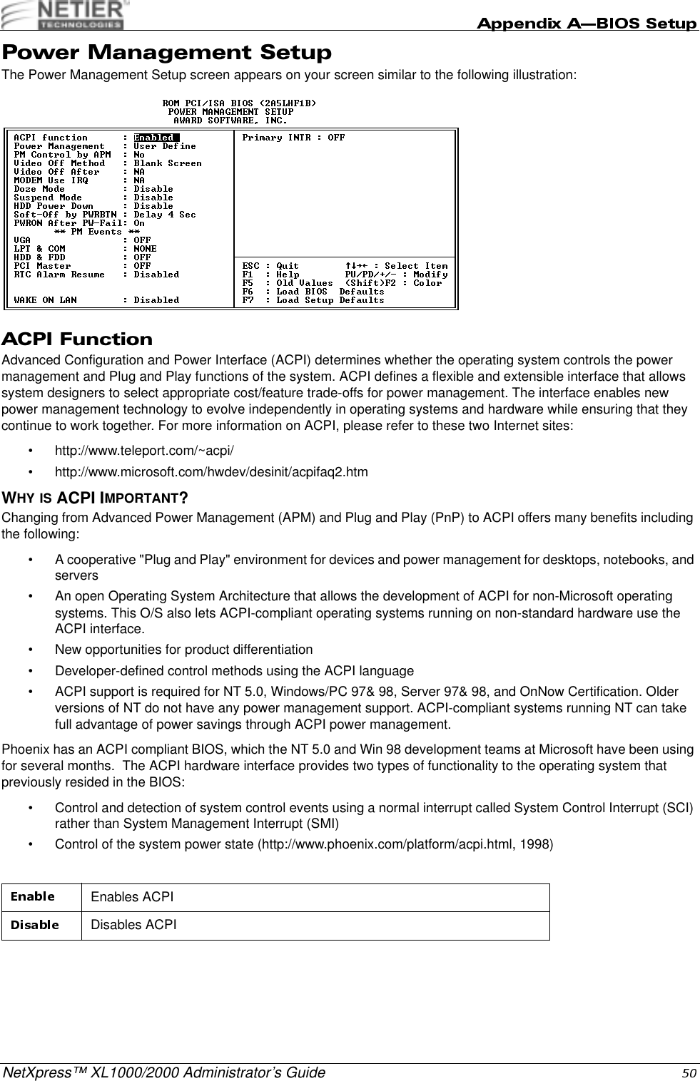
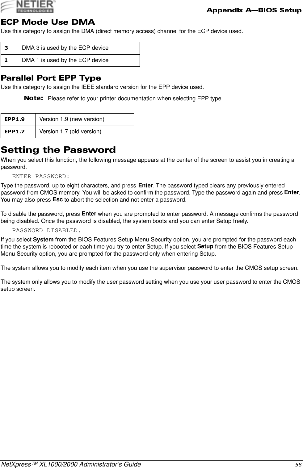
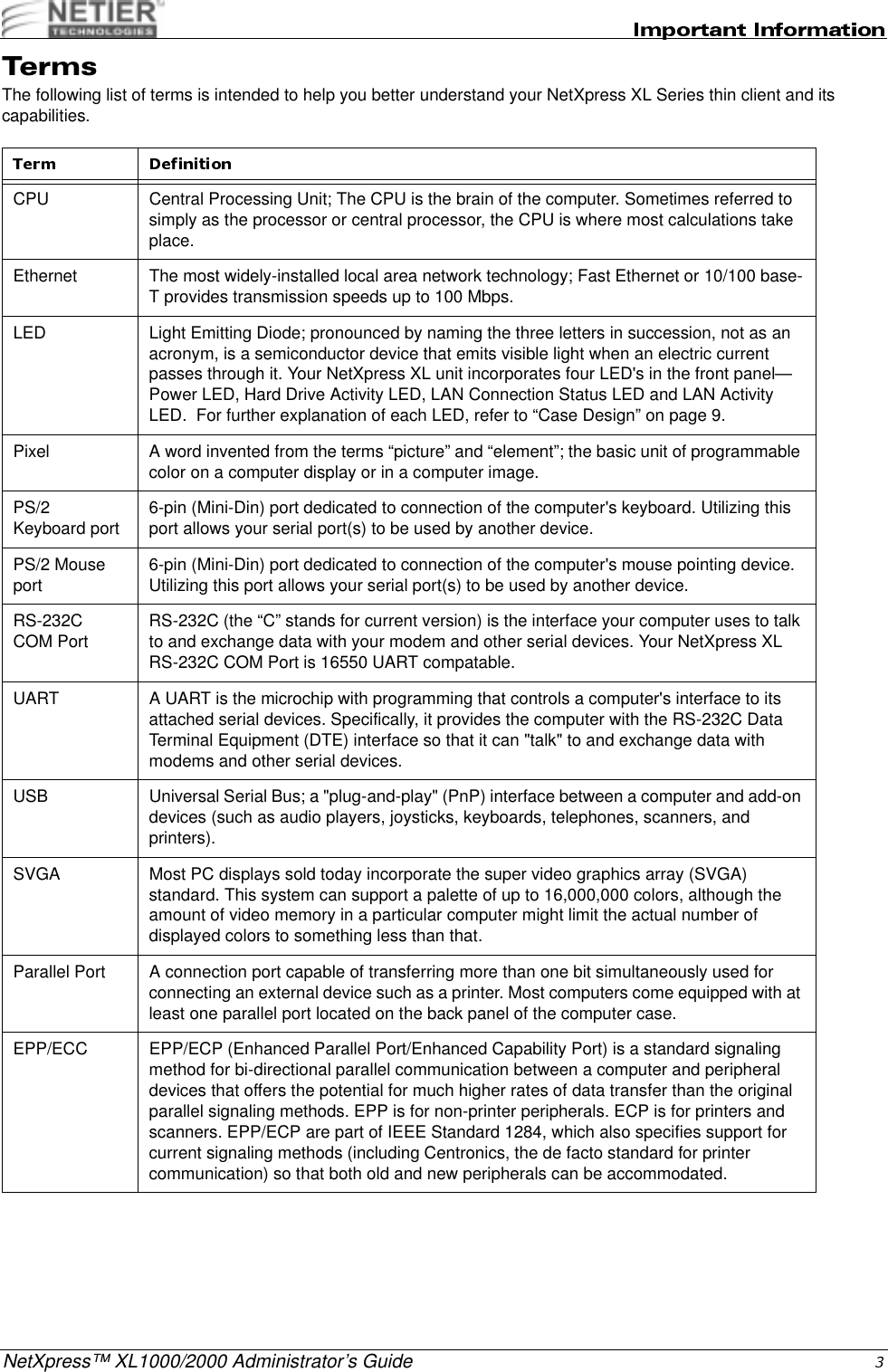
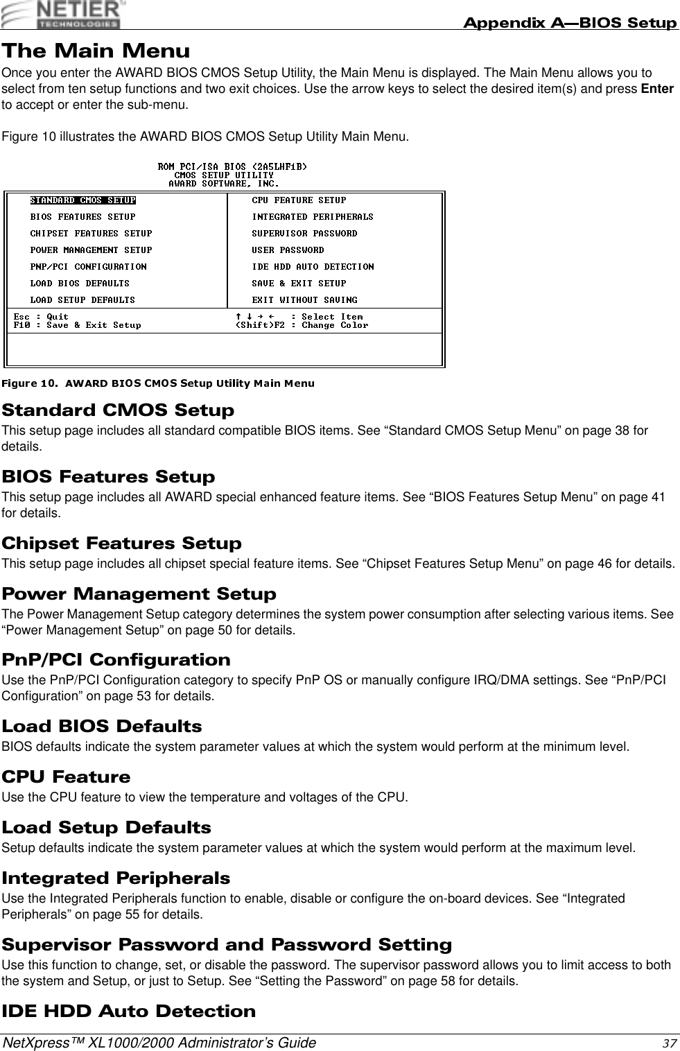
![NetXpress™ XL1000/2000 Administrator’s GuideF 049.DFORMATBefore TrueFFS can access a flash media, the media must be formatted, just as a floppy disk must be formatted before use. Formatting initializes the media and writes a new and empty DOS file system to the media. When formatting is complete, the media contains only a root directory.The Flash Disk is fully tested and formatted before the product is shipped, but it can be formatted more than once. Each time it is formatted, all data on the media is destroyed. When reformatting, the boot-image is retained by default.The DFORMAT syntax is:Usage: DFORMAT {drive-letter/WIN:segment} [/SIZE:size] [/USE:nnn] [/LABEL:label] [/DOSVER:n] [/SPARE:n] [/Y]The DFORMAT options are:Example 1: DFORMAT C:Formats the Flash Disk used as Drive C.Example 2: DFORMAT /WIN:D000Formats the Flash Disk located at memory address hex D000. If any other hard disk is present in the system, the Flash Disk is identified as drive D:CONFIGURING THE DISKONCHIP AS A BOOTABLE DISKThe Flash Disk fully supports the BOOT capability. For the Flash Disk to be bootable, it should be DOS formatted as bootable, like any floppy or hard disk required to be bootable.Example 1: SYS D:Changes the disk into a bootable medium, assuming the Flash Disk is disk D:.driver-letter DOS driver letter of the TrueFFS drive./WIN:Segment Memory address in which the DiskOnChip is located. Use either this flag or the driver-letter flag./SIZE:size The size of the flash media to be formatted (including the install partition). By default the entire media is formatted by DFORMAT. This option limits the formatted size./USE:nnn Percentage of available space on the flash media to be used for file storage. nnn can be any number from 1 to 100. Default is 99 (99%).The value of this option may affect the write performance of TrueFFS./DOSVER:dos-major-version Format for a target system running the specified DOS version. The default is the current DOS version (the one on which DFORMAT is executed). For example, /DOSVER:3 formats for DOS 3.X. Valid values are 1 to 6./SPARE:n Number of spare units. Default is 1. A value 0 selects a WORM (Write Once Read Many)./Y Do not pause for confirmation before beginning to format.](https://usermanual.wiki/Wyse-Technology/WT8440.User-Manual/User-Guide-165067-Page-69.png)
![NetXpress™ XL1000/2000 Administrator’s Guide0.0#(!I.04,9In case a firmware update is required, M-Systems will deliver a new .EXB file, which should be written into the firmware portion of the Flash media within the Flash Disk, Use the DUPDATE utility to write the .EXB file into the Flash media firmware portion.DUPDATE requires the DiskOnChip be preprogrammed with the previous firmware file, which is the default as the Flash Disk is shipped fully tested and programmed.The DUPDATE syntax is:DUPDATE [drive-letter/WIN:Segment] /S:BootImage /FIRSTExample 1: DUPDATE C:/S:DOC105.EXBProgram the firmware, which is supplied in DOC105.EXB file, into the DiskOnChip located as drive C:.Example 2: DUPDATE /WIN:D000 /S:DOC105.EXBProgram the firmware, which is supplied in DOC105.EXB file, into the DiskOnChip located at memory address hex D000. The DiskOnChip will be the last drive in the system (e.g., D: if one magnetic hard drive is already configured).Example 3: DUPDATE /WIN:D000 /S:DOC105.EXB /FIRSTProgram the firmware, which is supplied in DOC105.EXB file, into the DiskOnChip located at memory address hex D000. The DiskOnChip will be the first drive (C:) if a hard disk is available in the system.0;The DINFO Information utility provides background information regarding the DiskOnChip 2000 and the environment in which it operates. DINFO reports include:• TrueFFS drive letters• Installed software and its version compliance.• The size of the Flash media.The DINFO syntax is: DINFOExample: DINFOSearches the system for DiskOnChip.driver-letter TrueFFS drive DOS driver letter./WIN:Segment Memory address in which the DiskOnChip is located. Use either this parameter or the drive letter. The segment should be specified in Hex (e.g. /win:d000)./S:BootImage The boot image file of the new firmware to be written to the Flash Disk. Usually the file type is .EXB./FIRST Use this flag to program the DiskOnChip to be the first disk if more disks are installed in the system. This flag has no effect if the DiskOnChip is the only disk in the system.The /S parameter must be supplied when /FIRST flag is used.](https://usermanual.wiki/Wyse-Technology/WT8440.User-Manual/User-Guide-165067-Page-70.png)