Wyse Technology WT8440 Windows-Based Terminal User Manual
Wyse Technology Windows-Based Terminal Users Manual
Contents
- 1. User Manual
- 2. Special Accessories Instruction
- 3. Revised User Manual
User Manual

Home > Products > Winterm Thin Clients > Winterm 8000 Series Quick Reference
Products
Winterm Thin
Clients
General Purpose
Terminals
Software
Success Stories
White Papers
Download
Firmware
Find a Reseller
Winterm Evaluation
Winterm Virtual
Tour
Netier Products
Winterm 8000 Series Technical Reference Guides
Winterm Model 8360SE and 8230LE NTE-based Terminal Quick Reference Guide Version 4.3
PDF (446 KB)
Model 8360SE Quick Reference Guide Application Notes
PDF (18 KB)
Model 8440XL Hardware Administrator's Guide
Refer to sections and details relating to the XL2000 terminal for information applicable to the WT8440XL.
PDF (1.41 MB)
Citrix Device Services (CDS)
Citrix Device Services (CDS) provides basic ICA connectivity of Windows-based terminals and other ICA devices to Microsoft Windows NT Server 4.0, Terminal Server
Edition.
The CDS product provides participating ICA Windows-based terminals or fixed function device with an integrated ICA client the ability to: Log into TSE over an Ethernet LAN or
WAN TCP/IP connection ,establish an application session, map local COM ports, map local printers, easily upgrade to Citrix MetaFrame 1.8 or above
For a additional information about CDS, please click here.
Warranty Registration
Winterm 8000 Peripherals
Winterm Upgrades and Accessories
Wyse Rapport 3.0
centrally manage and upgrade all Winterm 3000 and 8000 series terminals
Microsoft Windows® 2000 Terminal Services Licensing Issues a Hotfix
Microsoft Windows® 2000 Terminal Services licensing has issued a hotfix to
help reduce the administrative overhead in managing TS license tokens.
have a Winterm thin client, click here to get the download and more
information from Microsoft
Need technical assistance? Complete our Support Request Form
Wyse Technology - Products - Winterm 8000 Series Technical Reference Guides http://www.wyse.com/products/winterm/quickstart/8000.htm
Copyright©1999 Netier Technologies, Inc.
More than just thin.™

NetXpress™ XL1000/2000 Administrator’s Guide
Thank you for purchasing the Netier NetXpress XL thin-client computer. Your satisfaction is important to us. If you
experience any problems, please call 1-888-603-1892 for friendly, helpful technical support. Or if you prefer, contact us
via Email at techsupp@netier.com.
Please read all instructions, and save these instructions for future reference. Always unplug your NetXpress XL
computer from the wall outlet before cleaning. Do not use liquid cleaners or aerosol cleaners. Use a damp cloth for
cleaning. Only use manufacturer-approved peripherals and attachments. Unapproved peripherals and attachments
may be hazardous to system operation.
Do not use your NetXpress XL thin-client computer near water.
Do not place this computer on an unstable cart, stand, or table. The computer may fall, causing serious personal injury
as well as damage to the appliance.
Slots and openings in the NetXpress XL case are provided for ventilation. To ensure reliable operation of the computer
and to protect it from overheating, do not block or cover these openings. Never place the NetXpress XL near or over a
radiator or other heat source. Also, do not place your NetXpress in a built-in installation, such as a bookcase or shelf,
unless proper ventilation is provided.
Operate your NetXpress XL only from the power source type indicated on the label. If you are not sure of the type of
power supplied in your home or office, please consult your value added reseller (VAR) or local power company.
The NetXpress XL is equipped with a three-wire grounding plug, which is a common plug type that incorporates a third
pin for grounding. This plug only fits into a grounding-type power outlet, which contains three receptacles. This design
provides added safety. If your outlet is not suited to accept the three-wire grounding plug, contact a certified electrictian
to replace the outlet that accepts three-wire grounding plugs.
Caution: Do not undertake any actions that inhibit proper electrical grounding (e.g., removing the
grounding prong or using two-wire plug adapters).
Do not allow anything to rest on the power cord. Position your NetXpress XL such that the power cord is protected from
any traffic or from heavy obstacles.
Follow all warnings and instructions listed on the computer.
To protect your NetXpress XL from power surges, unplug it from the wall outlet when not in use for long periods. Do
not overload wall outlets and extension cords as this can result in fire or electric shock.
Never push objects of any kind into your NetXpress XL computer case slots. Foreign objects can damage the
computer and may result in fire or electric shock.
In the event any liquid is spilled on the unit, immediately unplug the external power supply at the wall outlet. If any
liquid has penetrated openings in the unit, contact your hardware service provider before you attempt to apply power to
the unit again.
Do not attempt to service your NetXpress XL yourself. Opening or removing covers may expose you to dangerous
voltage or other hazards. Refer all servicing to qualified service personnel. Unplug this computer from the wall outlet
and refer servicing to qualified service personnel under the following conditions:
• When the power cord or plug is damaged or frayed.
• If liquid has been spilled into the computer.
• If the computer has been exposed to rain or water.
• If the computer does not operate normally when the operating instructions are followed. Adjust only those
controls that are covered by the operating instructions. Improper adjustment of other controls may result in
damage and will often require extensive work by a qualified technician to repair the computer.
• If the computer has been dropped or the cabinet has been damaged.
• When the computer exhibits a distinct change in performance, indicating a need for service.

NetXpress™ XL1000/2000 Administrator’s Guide
When replacement parts are required, be sure the service technician uses replacement parts approved by the
manufacturer. Use of unauthorized replacement parts may result in fire, electric shock, or other hazards.
Upon completion of any service or repairs to your NetXpress XL, ask the service technician to perform routine safety
checks to ensure the computer is in safe operating condition.
The information in this manual is subject to change without notice.
The information contained in this manual was reviewed and validated. While every precaution was taken during the
preparation of this manual, Netier Technologies, Inc. makes no warranty of any kind with regard to this material,
including, but not limited to, the implied warranties of merchantability and fitness for a particular purpose.
Netier Technologies, Inc. is not liable for errors contained herein or for incidental or consequential damages in
connection with the furnishing, performance, or use of this material.
No part of this document may be photocopied, reproduced, or translated to another language without prior written
consent of Netier Technologies, Inc.
First edition—July 1998
© Copyright 1998 by Netier Technologies, Inc.
This equipment has been tested and found to comply with the limits for a Class B computing device, pursuant to Part
15 of FCC Rules. Only peripherals (computer input/output devices, monitors, printers, etc.) certified to comply with the
Class B limits may be attached to this computer. Operation with non-certified peripherals is likely to result in
interference to operation.
NOTICE: This equipment generates and uses radio frequency energy, and if not installed and used in strict
accordance with this user guide, interference to operation may result. It has been type tested and found to comply with
the limits for a Class B computing device, pursuant to Part 15 of FCC Rules, which are designed to provide
reasonable protection against such interference in an office or residential installation. However, there is no guarantee
that interference will not occur in a particular installation. If this equipment does cause interference to radio or
television reception, which can be determined by turning the equipment on and off, you are encouraged to try to
correct the interference by one or more of the following measures:
• Reorient the receiving antenna of any adjacent devices.
• Relocate the NetXpress XL with respect to the device being effected.
• Plug the computer into an alternate outlet so that the NetXpress XL and the receiver are on different branch
circuits.
If necessary, consult your reseller for additional suggestions.
You may find the following booklet prepared by the Federal Communications Commission (FCC) helpful:
How to
Identify and Resolve Radio-TV Interference Problems
. This book is available from the U.S. Government Printing
Office, Washington, D.C. 20402.
NetXpress and the Netier logo are registered trademarks of Netier Technologies, Inc.
All other registered and unregistered trademarks are trademarks of their respective holders.

NetXpress™ XL1000/2000 Administrator’s Guide
The following list of terms is intended to help you better understand your NetXpress XL Series thin client and its
capabilities.
CPU Central Processing Unit; The CPU is the brain of the computer. Sometimes referred to
simply as the processor or central processor, the CPU is where most calculations take
place.
Ethernet The most widely-installed local area network technology; Fast Ethernet or 10/100 base-
T provides transmission speeds up to 100 Mbps.
LED Light Emitting Diode; pronounced by naming the three letters in succession, not as an
acronym, is a semiconductor device that emits visible light when an electric current
passes through it. Your NetXpress XL unit incorporates four LED's in the front panel—
Power LED, Hard Drive Activity LED, LAN Connection Status LED and LAN Activity
LED. For further explanation of each LED, refer to “Case Design” on page 9.
Pixel A word invented from the terms “picture” and “element”; the basic unit of programmable
color on a computer display or in a computer image.
PS/2
Keyboard port 6-pin (Mini-Din) port dedicated to connection of the computer's keyboard. Utilizing this
port allows your serial port(s) to be used by another device.
PS/2 Mouse
port 6-pin (Mini-Din) port dedicated to connection of the computer's mouse pointing device.
Utilizing this port allows your serial port(s) to be used by another device.
RS-232C
COM Port RS-232C (the “C” stands for current version) is the interface your computer uses to talk
to and exchange data with your modem and other serial devices. Your NetXpress XL
RS-232C COM Port is 16550 UART compatable.
UART A UART is the microchip with programming that controls a computer's interface to its
attached serial devices. Specifically, it provides the computer with the RS-232C Data
Terminal Equipment (DTE) interface so that it can "talk" to and exchange data with
modems and other serial devices.
USB Universal Serial Bus; a "plug-and-play" (PnP) interface between a computer and add-on
devices (such as audio players, joysticks, keyboards, telephones, scanners, and
printers).
SVGA Most PC displays sold today incorporate the super video graphics array (SVGA)
standard. This system can support a palette of up to 16,000,000 colors, although the
amount of video memory in a particular computer might limit the actual number of
displayed colors to something less than that.
Parallel Port A connection port capable of transferring more than one bit simultaneously used for
connecting an external device such as a printer. Most computers come equipped with at
least one parallel port located on the back panel of the computer case.
EPP/ECC EPP/ECP (Enhanced Parallel Port/Enhanced Capability Port) is a standard signaling
method for bi-directional parallel communication between a computer and peripheral
devices that offers the potential for much higher rates of data transfer than the original
parallel signaling methods. EPP is for non-printer peripherals. ECP is for printers and
scanners. EPP/ECP are part of IEEE Standard 1284, which also specifies support for
current signaling methods (including Centronics, the de facto standard for printer
communication) so that both old and new peripherals can be accommodated.

NetXpress™ XL1000/2000 Administrator’s Guide
The XL Series thin clients are manufactured using Integrated Scalable System Architecture™ (ISSA), which allows
upgrading of system components to meet almost any computing requirement.
Both the XL1000 and XL2000 thin clients include the following standard features:
• Trident CBi7 North bridge controller with integrated AGP video
• VIA VT82C686A South bridge controller with integrated SoundBlaster Pro Comp Audio
• Supports Socket-7/Super Socket-7 Processors
• 60~100 MHz FSB With Synchronous and Pseudo-synchronous Mode.
• Supports up to 600MHz, 64bit, Pentium-class CPU with MMX technology
• 512K Built-in L2 cache
• (2) 168-pin DIMM sockets support up to 128MB of FP, EDO, & PC-100 SDRAM.
• Integrated Super I/O, Includes FDC, LPT, COM 1, & USB 1& 2
• Integrated AGP 64-bit 2D/3D Graphics Accelerator.
• Integrated H/W Soundblaster Pro/Direct Sound AC ’97 2.0 compliant Audio.
• 100/10 Base-T Ethernet LAN w/WakeOnLan (WOL) & Pre boot eXecution Environment (PXE) functions.
• On-board hardware monitoring ADM/ACPI.
• M-Systems DiskOnChip flash storage device support.
• Compact Flash storage device option.
• Internal Hard Disk Drive option (up to 10GB).
• Internal Floppy Disk Drive option.
• PS/2 mouse port
• PS/2 keyboard port
• Serial port (COM1)
• Parallel port (LPT1)
• Universal Serial Bus (USB) ports (USB1 & USB2)
• Mic, line-in, and line-out ports
• SVGA port
• External ATX power supply (50-Watt)
In addition to the features above, the XL2000 is also equipped with the following items:
• 1 x ISA/PCI riser card (supports qualified industry expansion cards including: modems, token ring, ISDN,
video conferencing, multiple serial port, wireless LAN, etc,.)
The following optional items are available for use in the XL2000:
• 24X CD-ROM drive with a slim form factor

NetXpress™ XL1000/2000 Administrator’s Guide
The NetXpress XL Series thin client consists of the following components:
• P5 Motherboard
• PS/2 Keyboard
• PS/2 Mouse
• 50-Watt ATX external power supply
• Thin-client case with the following dimensions:
XL1000 case dimensions (W x H x D): 9.5 x 1.3 x 8.6 in.
24 x 3.5 x 22 cm
XL2000 case dimensions (W x H x D): 9.5 x 1.9 x 8.6 in.
24 x 5.0 x 22 cm

NetXpress™ XL1000/2000 Administrator’s Guide
This section is written to protect both you and the system. Please read this section carefully to maximize system
service life.
The operating voltage for the switching power should cover the range of 90 VAC~265 VAC or the system may be
damaged.
Caution: Use only the external switching power adapter unit that came with your NetXpress XL unit. Using
a different switching power adapter may cause system damage.
!
Place your NetXpress XL on a solid, level surface. Allow enough room for the rear panels to ensure easy access to I/O
ports.
Avoid installing the system in an extremely hot or cold environment. Consult the following information for suitable
operating and non-operating temperature ranges.
Operating temperature range: 32 °F~104 °F (0 °C~40 °C)
Non-operating temperature range: -14 °F~140 °F (-10 °C~60 °C)
Lowest operating ambient temperature: 32 °F (0 °C)
With CPU heat sink and fan:
Operating temperature range: 32 °F~85 °F (0 °C~29 °C)
Non-operating temperature range: -14 °F~140 °F (-10 °C~60 °C)
Lowest operating ambient temperature: 32 °F (0 °C)
Avoid moving the system rapidly from a hot place to a cold place or vice versa. Otherwise, damage can result from
condensation forming inside the system. Keep the system away from damp air, water, and dust.
Operating ambient humidity: 0%~80% (non-condensing)
Non-operating relative humidity: 0%~80% (non-condensing)
Do not locate the system in places with strong vibrations. Strong vibrations may cause serious damage to the internal
hard disk. To avoid interference with other electronic equipment, do not locate the system directly adjacent to a radio,
television, or other communication system.
Caution: Avoid placing liquids near the system.
100 VAC~240 VAC 90 VAC~264 VAC 50/60 Hz
NetXpress™ XL1000/2000 Administrator’s Guide
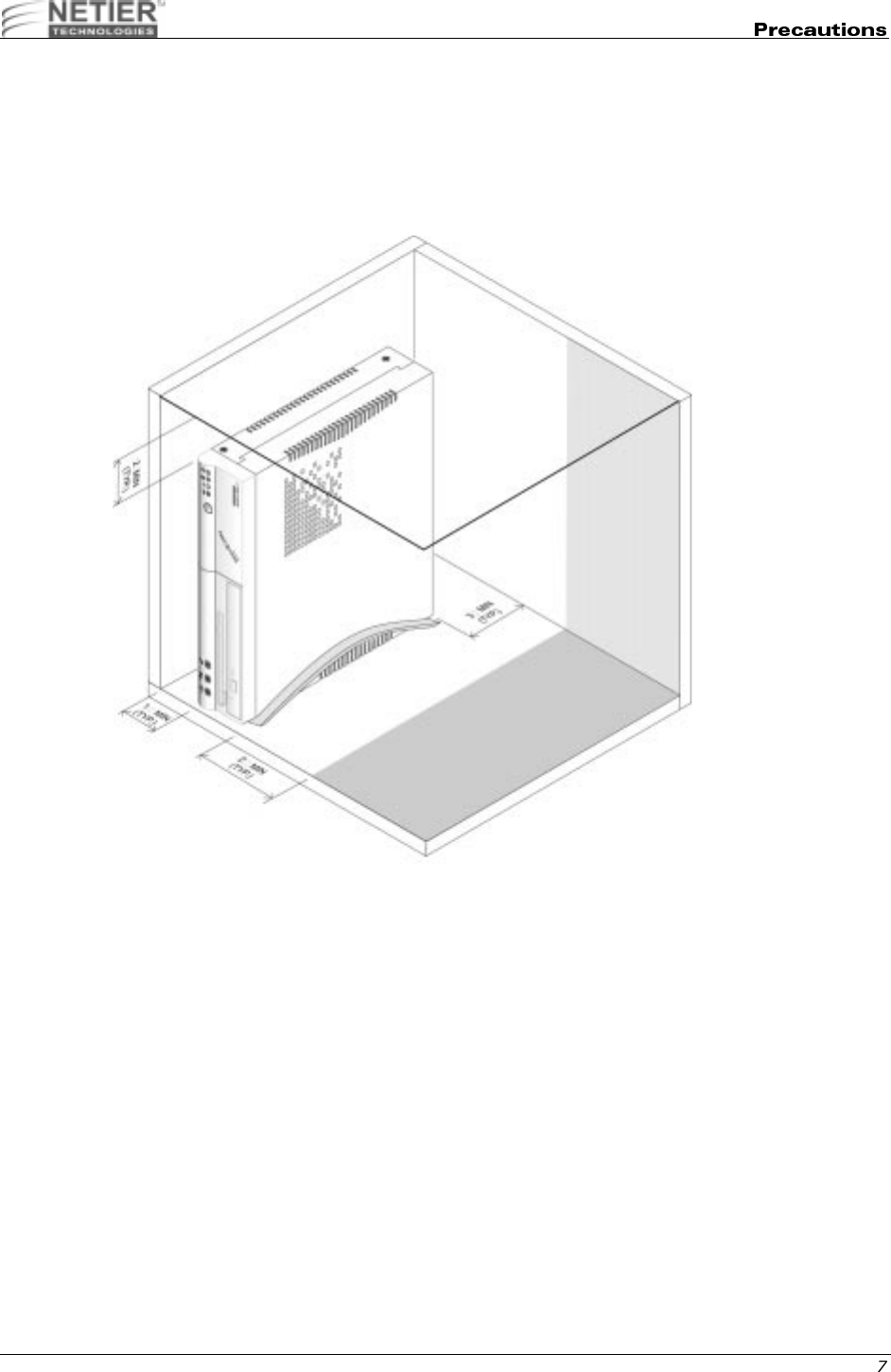
It is recommended you do not place objects directly on top of the NetXpress XL thin client as this may overheat the unit
and may cause permanent damage, which may void your warranty. Please follow the recommended postioning
diagrams below.
Refer to the illustrations on the following pages for recommended positioning.
XL Series Vertical Mount Position
NetXpress™ XL1000/2000 Administrator’s Guide
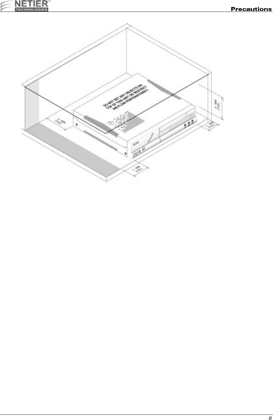
Caution: Do not place any objects on top of the unit, regardless of vertical or horizontal positioning. Do
not restrict air flow to vent holes in the case under any circumstances.
XL Series Horizontal Mount Position
NetXpress™ XL1000/2000 Administrator’s Guide
"
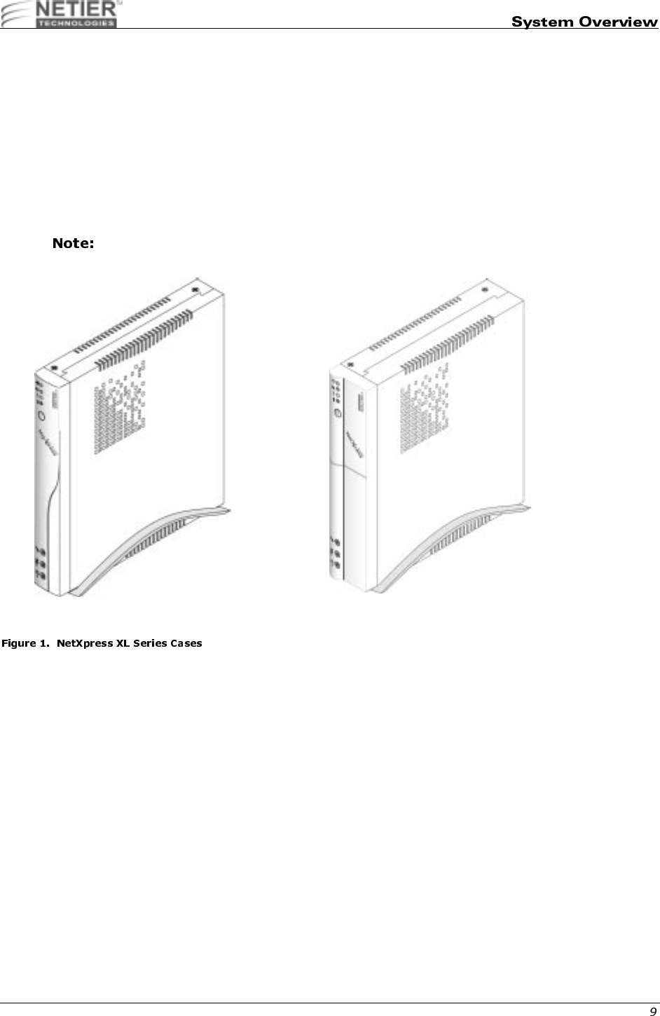
The NetXpress XL case encloses the motherboard and other important system components. The heart of the system
is the XL motherboard, which contains the CPU, RAM, BIOS, and LAN adapter.
Caution: The XL Series cases are fitted with ventilation holes to facilitate heat dissipation. Do not obstruct
the ventilation holes under any circumstances or the device could become inoperative.
Both the XL1000 and XL2000 can support optional floppy, hard disk drive and compact flash module. However, the
XL2000 provides additional support for a CD-ROM drive as well as an expansion slot for a PCI/ISA adapter. Please
consult your sales representatives for supported combinations of these options.
If the compact flash module is incorporated in the XL2000 the PCI/ISA riser card cannont be used.
XL1000 Case XL2000 Case
NetXpress™ XL1000/2000 Administrator’s Guide
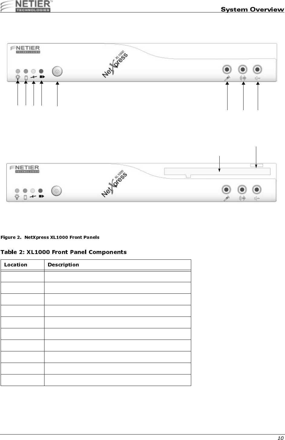
Figure 2 illustrates the NetXpress XL1000 front panels.
1 Power LED (blinking denotes suspend mode)
2 HDD/DiskOnChip Activity LED
3 LAN Connection LED
4 LAN Activity LED
5 Power On/Off
6 Microphone jack
7 Audio Line In
8 Speaker Out
9 Floppy Disk Drive (Optional)
10 Floppy diskette ejection button (if equipped)
XL1000 Without 3.5-in. Floppy Disk Drive
123456 7 8
9
10
XL1000 With 3.5-in. Floppy Disk Drive
NetXpress™ XL1000/2000 Administrator’s Guide
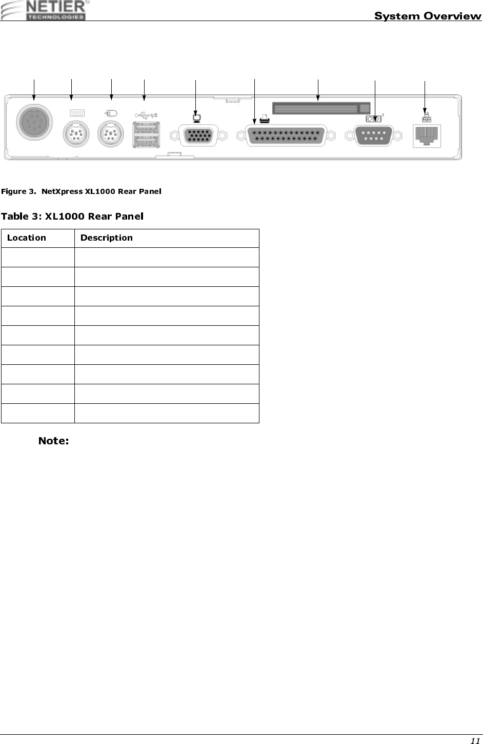
Figure 3 illustrates The NetXpress XL1000 rear panel.
Full use of all ports is dependent upon the operating system selected and the presence of proper
drivers.
0 External ATX power supply input
1 PS/2 Keyboard Port
2 PS/2 Mouse Port
3 USB Ports
4 VGA Port
5 Parallel Port
6 Compact Flash Module (optional)
7 Serial Port
8 Ethernet RJ45 connector
345
2
1
06
XL1000 Rear Panel
78
NetXpress™ XL1000/2000 Administrator’s Guide
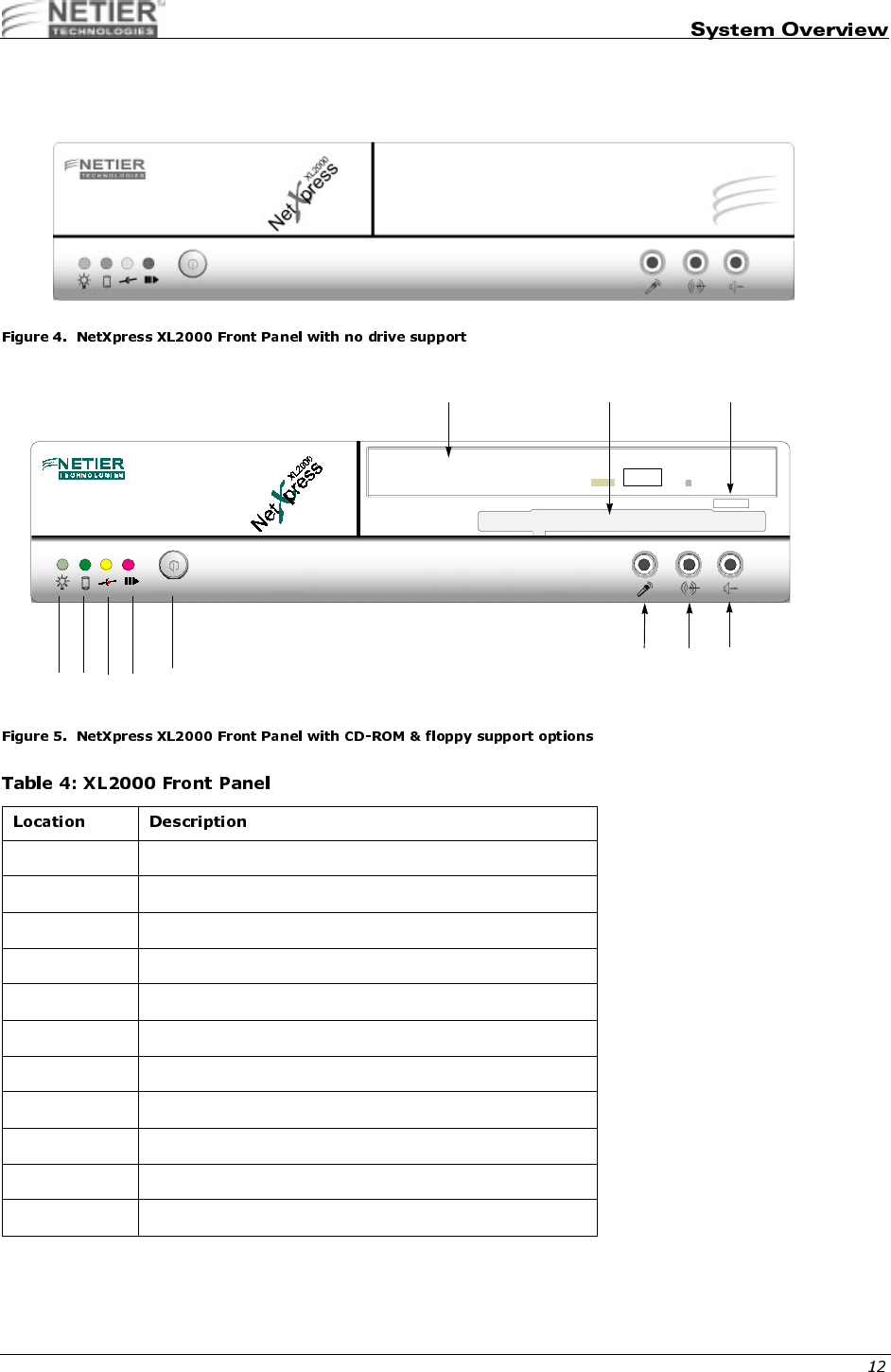
Figure 4 and Figure 5 illustrate the NetXpress XL2000 front panel.
1 Power LED (blinking denotes suspend mode)
2 HDD/DiskOnChip Activity LED
3 LAN Connection LED
4 LAN Activity LED
5 Power On/Off
6 CD-ROM drive (optional)
7 Floppy disk drive (optional)
8 Floppy diskette eject button (if equipped)
9Mic
10 Line In
11 Speaker Out
9
6 7 8
10
5
1234
11
NetXpress™ XL1000/2000 Administrator’s Guide
Caution: When connecting or disconnecting components or equipment, ensure the computer and related
equipment are turned off and your computer is disconnected from the power source. Plugging or
unplugging any item when the computer is receiving power can cause power surges and damage
your computer.
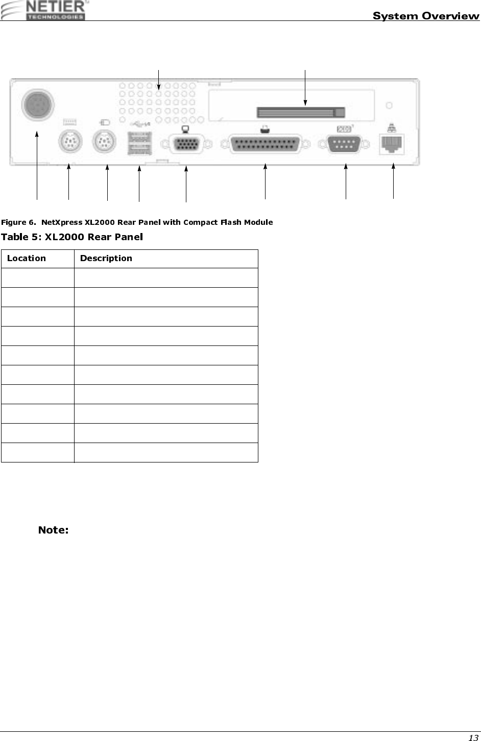
Full use of all ports is dependent upon the operating system selected and the presence of the proper
drivers.
0 External ATX power supply input
1 PS/2 Keyboard Port
2 PS/2 Mouse Port
3 USB Ports
4 VGA Port
5 Parallel Port
6 Serial Port
7 Ethernet RJ45 connector
8 Compact Flash Module (Optional)
9 System Ventilation (fan option available)
012356
9 8
47

NetXpress™ XL1000/2000 Administrator’s Guide
The following section details technical data for the NetXpress XL1000 and XL2000 thin-client computers.
"
NetXpress XL Series thin-client access devices are powered by the P5 Motherboard. The table below lists P5
motherboard specifications:
ZIF Socket for Socket-7/Super-7 processors
Supports Pentium class processors up to 600MHz as available.
Trident CBi7 North bridge controller with integrated AGP video
VIA VT82C686A South bridge controller with integrated
SoundBlaster Pro Audio
2Mbit Award Flash BIOS, supports P&P APM1.2
BIOS quick booting
CMOS recall selection
Support for Wake On LAN
Support for Pre boot eXecution Environment (PXE) function
Optional customer splash screen from BIOS booting screen
512KB PB-SRAM on-board, using 64KX64 chip
Two DIMM sockets, supporting 8MB to 128MB, each 16/32/64MB
EDO, FP, PC/100 SDRAM memory modules (currently available)
Advanced memory ECC/EC function
Enhanced IDE interface x 1, supports 2-IDE devices, UltraDMA33
master mode PCI-EIDE
60~100MHz operation with synchronous or pseudo-synchronous
mode
PCI-2.2 compliant
32-bit 3.3v with 5v tolerant inputs
Integrated AGP 64-bit single cycle 2D/3D graphics accelerator
Supports 2~8MB of Frame Buffer
Extended screen resolution up to 1600x1200
Direct-X 6 and OpenGL ICD API
Integrated 24-bit 230MHz true color DAC
VMI to MPEG-1/MPEG-2 and video decoder
Real time DVD MPEG-2 and AC-3 playback
Integrated hardware SoundBlaster Pro/Direct Sound AC '97
compliant digital audio controller with PCI master interface
Hardware assisted FM synthesis
Standard v1.0/v2.0 codec I/F for single or cascaded AC '97
codecs
Universal Serial Bus ports x 2
USB v1.1 and Intel Universal HCI v1.1 compatible
1 x Mini-DIN connector for PS/2 keyboard

NetXpress™ XL1000/2000 Administrator’s Guide
These specifications are subject to change without notice.
!"
1 x Mini-DIN connector for PS/2 mouse
CPU temperature monitoring
CPU core, system power voltage detection
Realtek RTL-8139B(F)
100Base-TX/10Base-T Ethernet with PCI master interface
Support for Wake On LAN
Support for Pre-boot eXecution Environment (PXE) function
M-Systems DOC2000 socket x 1 (32-pin DIP JEDEC standard)
M-Systems DIM2000 socket x 1 (144-pin SoDIMM future option)
Compact Flash daughter card w/ejector (option)
Switching voltage regulator on-board for full range processor
voltage requirements.
Operating Temperature range:
Non-operating temperature range:
32 °F~104 °F (0 °C~40 °C) [With heat sink and fan]
-14 °F~140 °F (-10 °C~60 °C)
Board Physical W x D x H (overall) = 230mm (9-1/8") x 207mm (8-1/8") x 1.3mm (0.051")
CPU ZIF Socket-7/Super Socket-7 support
Main Memory 2 x 168-pin DIMM sockets
L2 Cache 512KB on-board
Flash File System 1 x 32-pin DIP JEDEC standard socket
144-pin SoDIMM (future option)
Compact Flash 1 x IDE compact flash ejector header (optional)- Selectable as master or
slave drive
Expansion Bus 1 x PCI/ISA Riser card support(XL 2000)
Primary IDE header 1 x 44-pin 1mm pitch header
Serial port 1 x 9-pin D-SUB RS232 FIFO (16550 compatible) Serial port connector
Parallel port 1 x 25-pin D-SUB Parallel port (SPP/EPP/ECP) connector
USB ports 2 x USB connectors/stacked
SVGA port 1 x 15-pin High Density D-SUB
Audio ports 1 Microphone Input
1 Stereo Audio Output
1 Stereo Audio Input
Keyboard port 1 PS/2 style keyboard port
Mouse port 1 PS/2 style mouse port
Power 1 (8-pin) DC power input supporting external ATX power supply
Power Switch 1 Momentary "Soft" power switch. Bezel mounted ON/OFF/SUSPEND

NetXpress™ XL1000/2000 Administrator’s Guide
Certifications Power Module - UL / C-UL / CE / TUV / CSA
Case - FCC / CE
XL1000 W x D x H (overall) = 240mm (9-1/2") x 220mm (8-9/16") x 35mm (1-3/16")
XL2000 W x D x H (overall) = 240mm (9-1/2") x 220mm (8-9/16") x 50mm (1-15/
16")
Power Supply External 50w AC Auto switching - Supports ATX function power connection

NetXpress™ XL1000/2000 Administrator’s Guide
#
SYSTEM MEMORY CONFIGURATION
The core chipset of the NetXpress XL Series accepts 16/32/64/128/256MB FP, EDO, PC-100, or PC-66 SDRAM
Modules as available.
Any memory modules used in the NetXpress SL Series need to conform to the proper
specifications. Please contact your reseller or Netier Technical support for more information.
CACHE RAM CONFIGURATION
Table 6 lists the L2 cache RAM configuration.
VGA MEMORY CONFIGURATION
Video memory is reserved from the main system memory via BIOS control settings. Optional memory settings include
2/4/8MB.
512 KB 64 K x 64 Pipeline 1 U12
NetXpress™ XL1000/2000 Administrator’s Guide
Use the following jumper setting configurations to configure specific CPU’s and enable, disable, or change system
functions.
Please refer to Figure 7 on page 17 for all jumper locations.
#$"%&'(
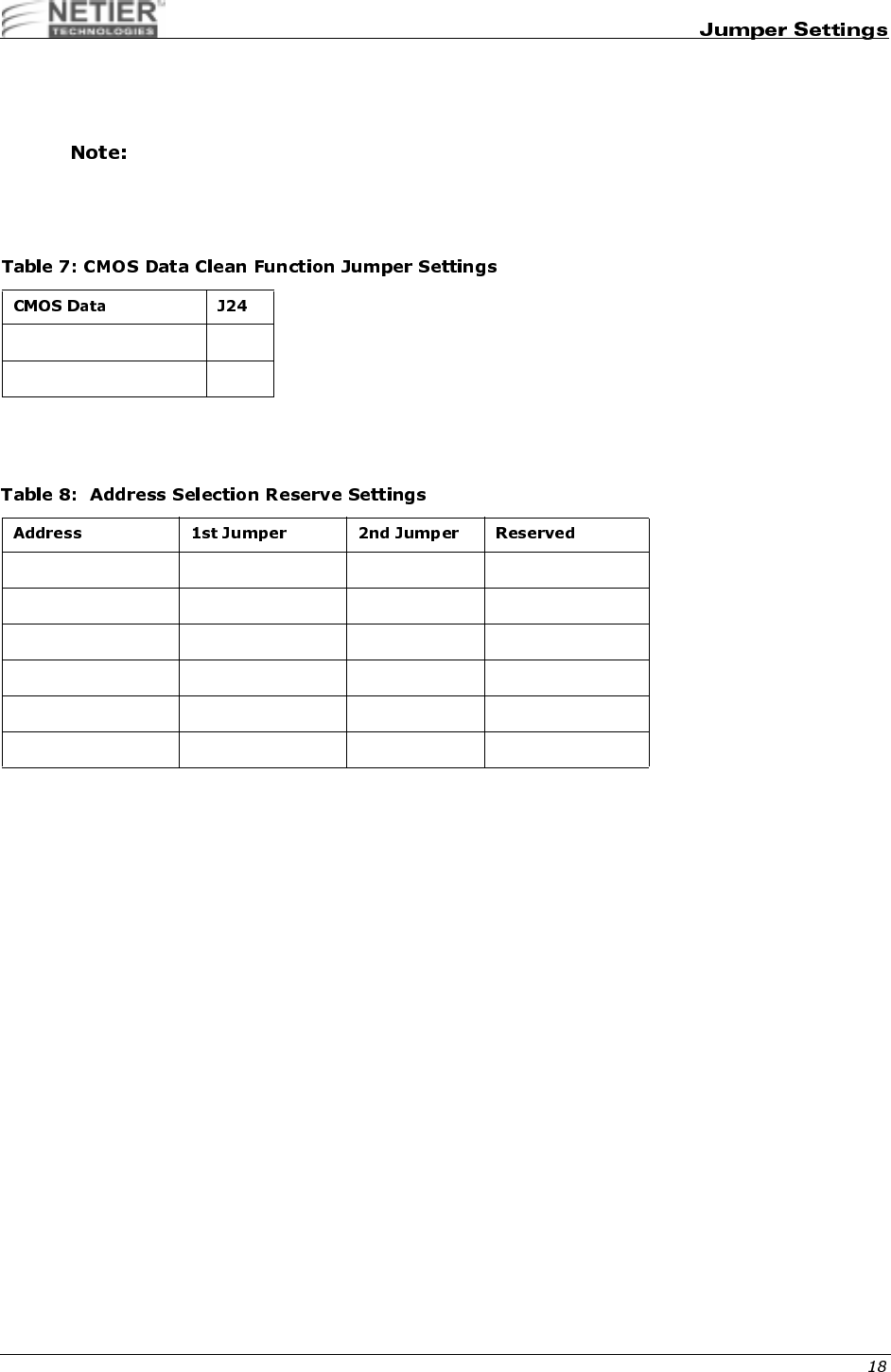
Table 7 lists the CMOS data clean function jumper settings.
#"$
Address selection reserve settings.
Clean 2-3
Normal (default) 1-2
0C800H - 0C9FFH R06 R08 VGA
0CC00H - 0CDFFH R06 R07 VGA
0D000H - 0D1FFH R05 R08 OPT. ROM
0D400H - 0D5FFH R05 R07 D.O.C.
0D800H - 0D9FFH R04 R08 BOOT ROM
0DC00H - 0DDFFH R04 R07 BOOT ROM
NetXpress™ XL1000/2000 Administrator’s Guide
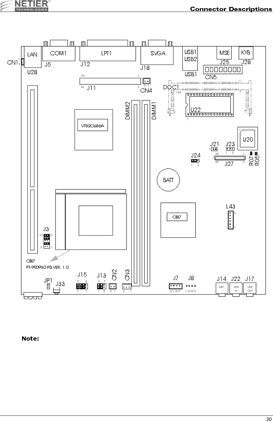
The following information describes the pin numbers and assignments for the XL 1.0 Motherboard connectors.
#%&'()*+,-$./
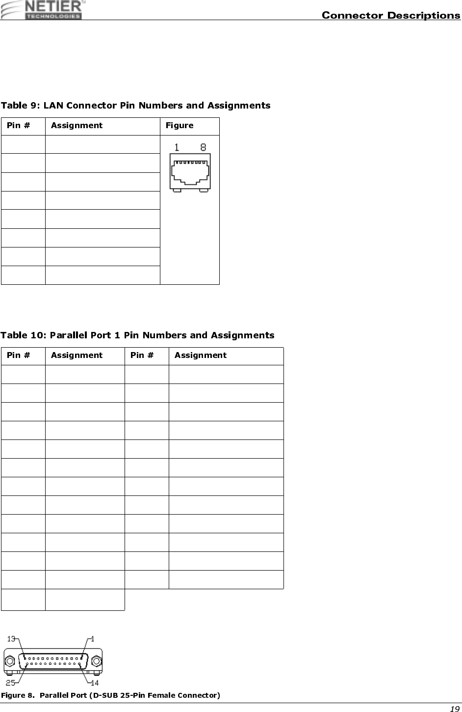
The following table lists the LAN connector pin numbers and assignments.
%0'.+',-$)
Table 10 lists the parallel port connector pin numbers and assignments. See Figure 8 on page 19 for more information.
1 Transmit output (+)
2 Transmit output (-)
3 Receive input (+)
4NC
5NC
6 Receive input (-)
7NC
8NC
1 Strobe (-) 14 Auto feed (-)
2 Data bit 0 15 Error (-)
3 Data bit 1 16 INIT (-)
4 Data bit 2 17 SLCT IN (-)
5 Data bit 3 18 Signal Ground
6 Data bit 4 19 Signal Ground
7 Data bit 5 20 Signal Ground
8 Data bit 6 21 Signal Ground
9 Data bit 7 22 Signal Ground
10 ACK (-) 23 Signal Ground
11 Busy 24 Signal Ground
12 Paper empty 25 Signal Ground
13 SLCT
NetXpress™ XL1000/2000 Administrator’s Guide
1,%0'.2',-$)+
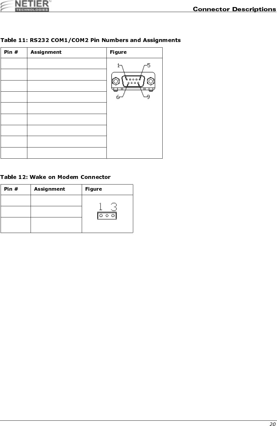
Table 11 lists the RS232 COM1pin numbers and assignments.
34,%'1-$)1
1 Data carrier detect
2 Receive data
3 Transmit data
4 Data Terminal ready
5 Signal Ground
6 Data set ready
7 Request to send
8 Clear to send
9 Ring indicator
1 +5Vcc Standby
2 Ground
3 Ring-In (R1)
NetXpress™ XL1000/2000 Administrator’s Guide
56#%0'.+',-$)/
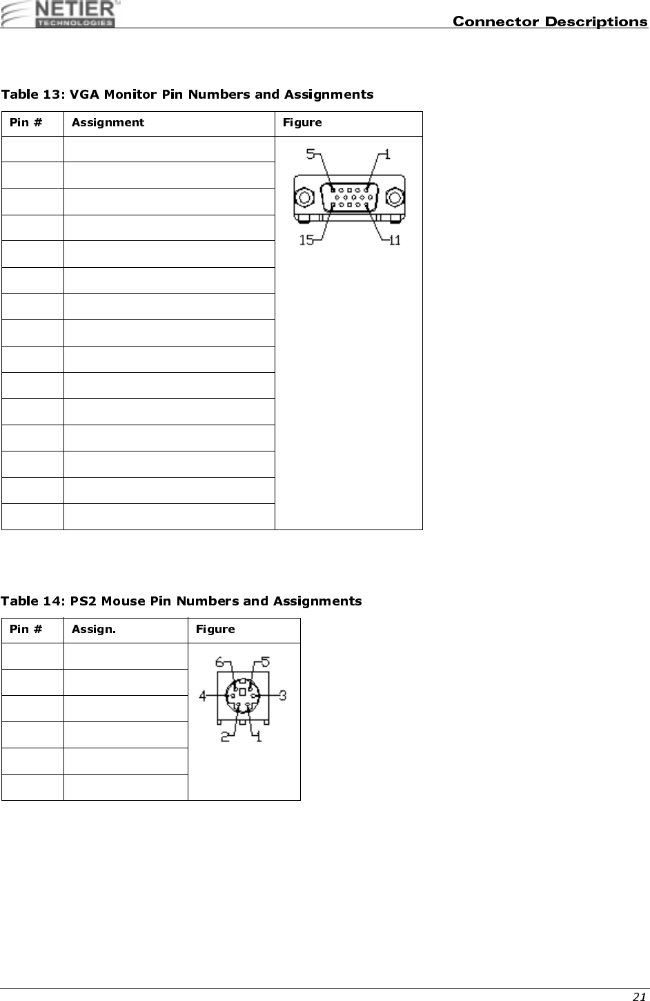
Table 13 lists VGA monitor pin numbers and assignments.
%07'-$)+
Table 14 lists PS2 mouse pin numbers and assignments.
1 Red signal
2 Green signal
3 Blue signal
4NC
5 Ground
6 Red ground
7 Green ground
8 Blue ground
9 VCCF
10 Ground
11 NC
12 MID1
13 H sync.
14 V sync.
15 MID3
1 Mouse data
2NC
3 Ground
4+5 V
5 Mouse clock
6NC
NetXpress™ XL1000/2000 Administrator’s Guide
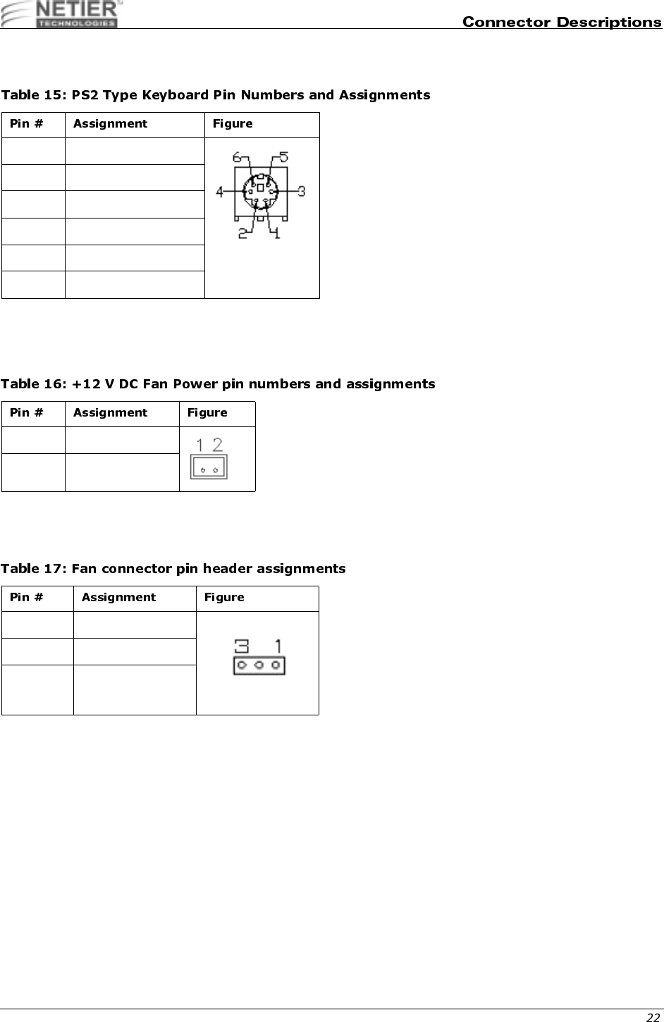
KEYBOARD (PC AT STANDARD OR PS2 TYPE): J28
Table 15 and Table 16 list pin numbers and assignments for PS2 keyboards.
Table 16 lists +12 V DC fan power pin numbers and assignments
850,9$,:,*
%'1-$,1
Table 17 list the fan connector pin header assignments.
1 Keyboard data
2Mouse Data
3 Ground
4+5 V
5 Keyboard clock
6 Mouse Clock
1 Ground
2+12 V
1 Ground
2CPUFN
3CPUFAN1
NetXpress™ XL1000/2000 Administrator’s Guide
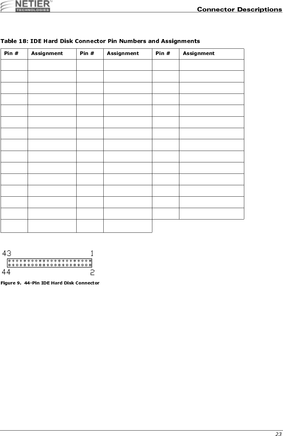
;0!<04,%'**'-$)
Table 18 lists IDE hard disk connector pin numbers and assignments.
1 Reset 16 Data bit 14 31 IRQ 14
2 Ground 17 Data bit 0 32 NC
3 Data bit 7 18 Data bit 15 33 Disk address 1
4 Data bit 8 19 Ground 34 NC
5 Data bit 6 20 NC 35 Disk address 0
6 Data bit 9 21 IDE DRQ 36 Disk address 2
7 Data bit 5 22 Ground 37 Disk chip select 0
8 Data bit 10 23 Disk Write 38 Disk chip select 1
9 Data bit 4 24 Ground 39 Disk LED
10 Data bit 11 25 Disk read 40 Ground
11 Data bit 3 26 Ground 41 +5 V
12 Data bit 12 27 Disk ready 42 +5 V
13 Data bit 2 28 NC 43 Ground
14 Data bit 13 29 IDE DACK 44 NC
15 Data bit 1 30 Ground
NetXpress™ XL1000/2000 Administrator’s Guide
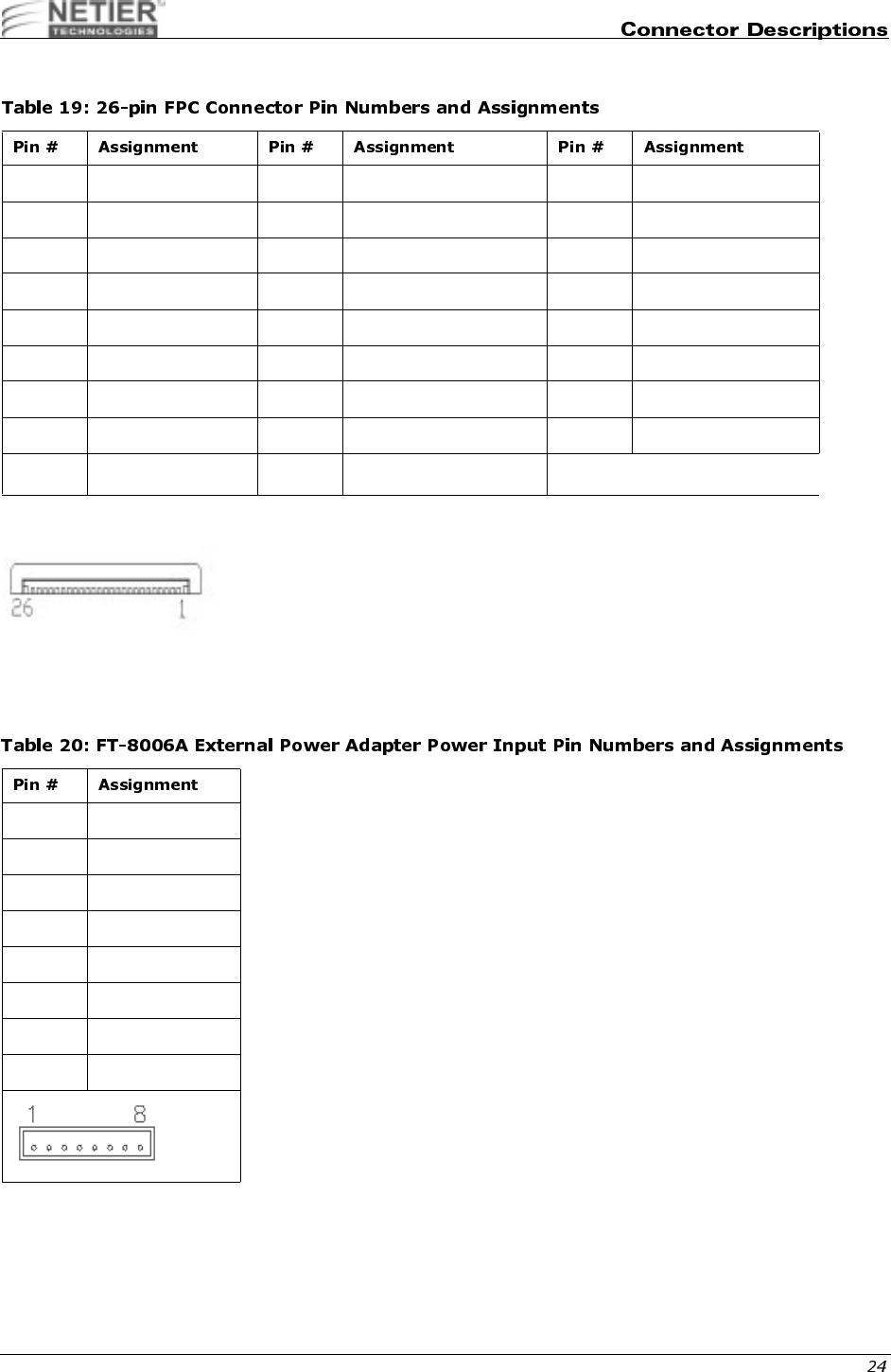
7',, #$)=
9;('/7#!>#(9#%'
/'-$,+
Table 20 lists the FT-8006A external power adapter pin numbers and assignments.
1 Vcc 10 Motor on 0 19 Ground
2 Index 11 NC 20 Track 00
3 Vcc 12 Data direction 21 Ground
4 Driver select 2 13 Density select 22 Write protected
5 Vcc 14 Step motor active 23 Ground
6 Disk change 15 NC 24 Read data
7 NC 16 Write data 25 Ground
8 NC 17 Ground 26 Head select
9 NC 18 Write gate
1 +5V IN
2 +5V IN
3+12V IN
4 Ground
5-12V IN
6 Power On signal
7 +5V Standby
8 Ground
NetXpress™ XL1000/2000 Administrator’s Guide
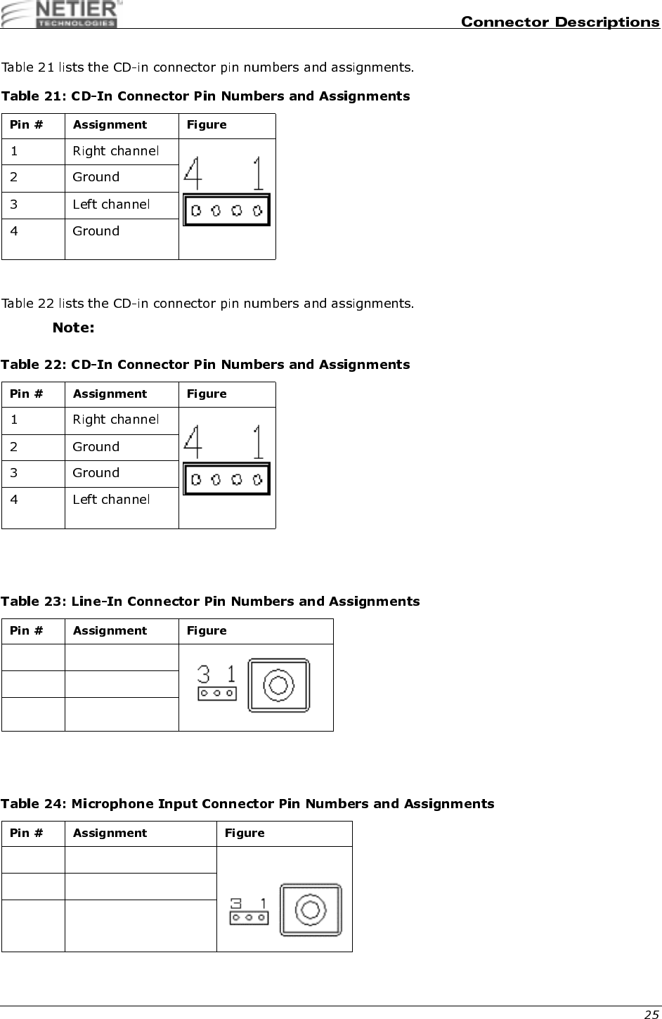
,0';,%'*'-$)=
CD-IN CONNECTOR (PIN-HEADER 4-PIN): J8 (OPTIONAL)
Header is not populated by default.
#',$)
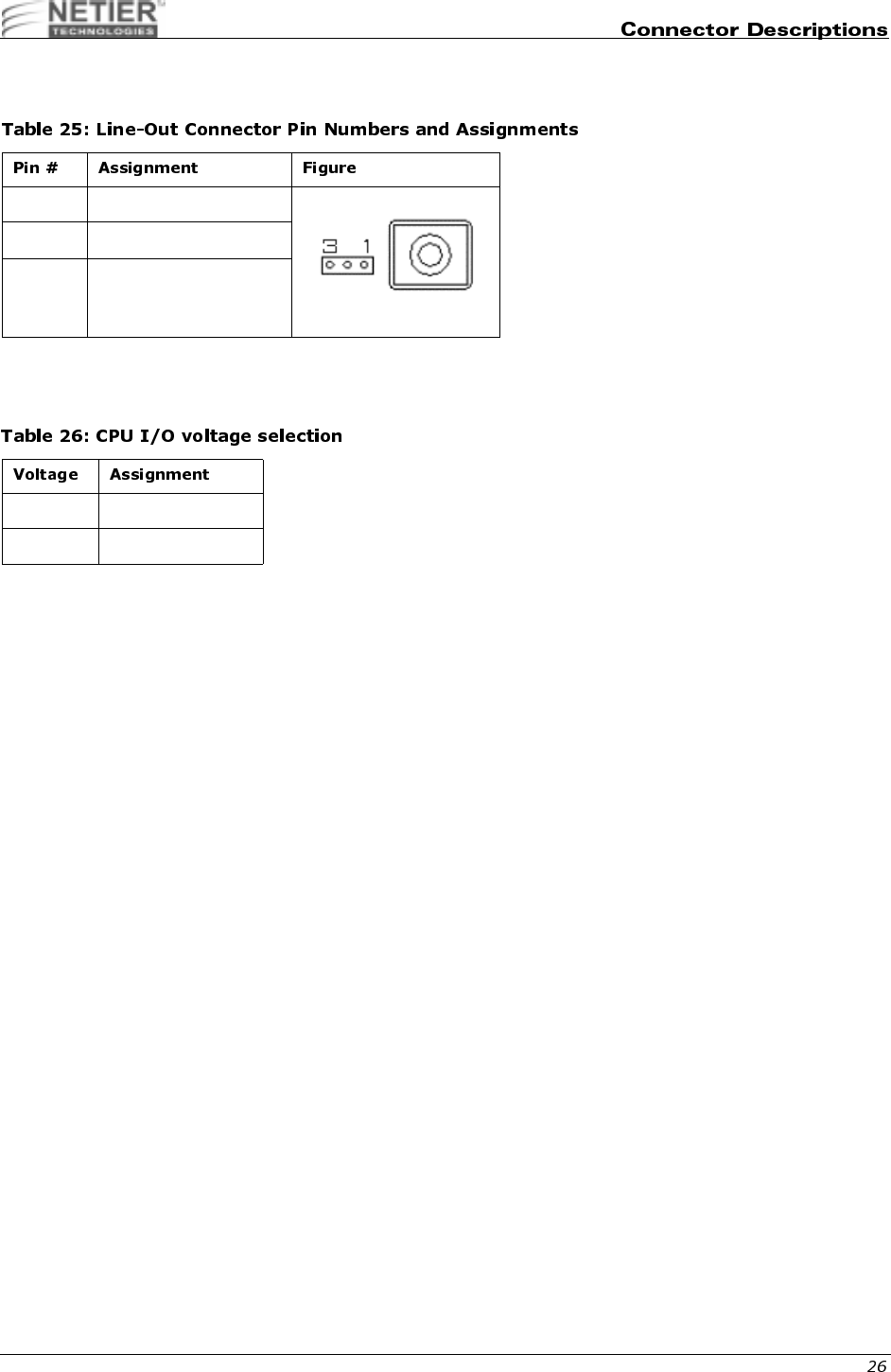
Table 23 list line-in connector pin numbers/assignments.
;,$)*
Table 24 lists the microphone input connector pin numbers and assignments.
1 Right channel
2 Ground
3 Left channel
1 Microphone signal
2 Ground
3NC
NetXpress™ XL1000/2000 Administrator’s Guide
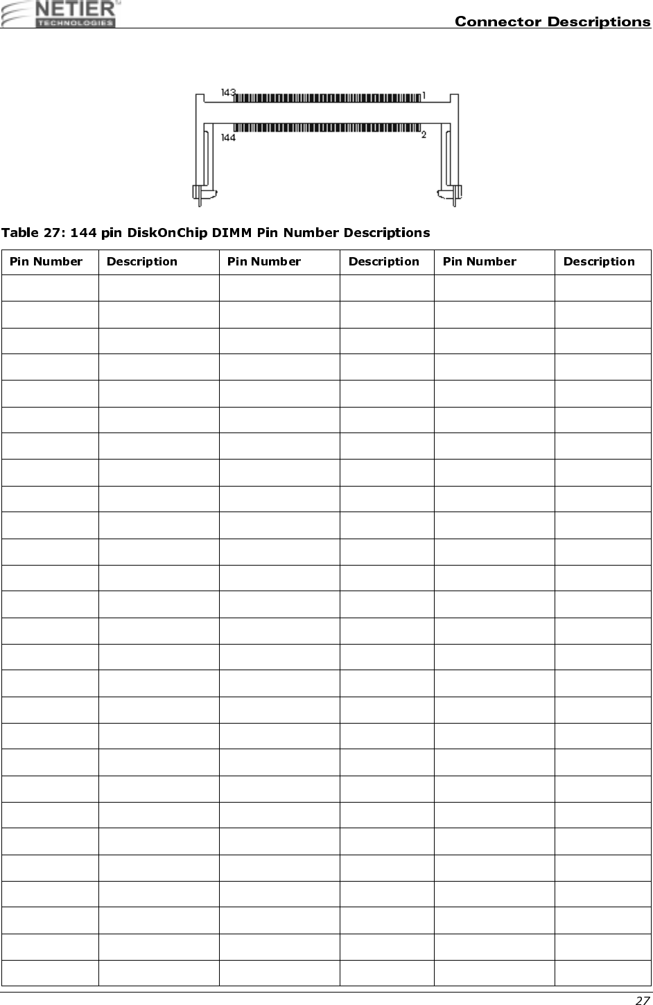
)(("$"##*"$)+*$+
1 GND 49 D13 97 D22
2 GND 50 No Connect 98 No Connect
3 D0 51 D14 99 D23
4 No Connect 52 No Connect 100 No Connect
5 D1 53 D15 101 VCC
6 No Connect 54 No Connect 102 VCC
7D2 55 GND103 A6
8 No Connect 56 GND 104 A7
9 D3 57 No Connect 105 A8
10 No Connect 58 No Connect 106 A11
11 VCC 59 No Connect 107 GND
12 VCC 60 No Connect 108 GND
13 D4 61 No Connect 109 A9
14 No Connect 62 No Connect 110 A12
15 D5 63 VCC 111 A10
16 No Connect 64 VCC 112 No Connect
17 D6 65 RESET# 113 VCC
18 No Connect 66 No Connect 114 VCC
19 D7 67 WE# 115 No Connect
20 No Connect 68 No Connect 116 No Connect
21 GND 69 No Connect 117 No Connect
22 GND 70 No Connect 118 No Connect
23 CE# 71 No Connect 119 GND
24 No Connect 72 No Connect 120 GND
25 No Connect 73 OE# 121 D24
26 No Connect 74 No Connect 122 No Connect
27 VCC 75 GND 123 D25
NetXpress™ XL1000/2000 Administrator’s Guide
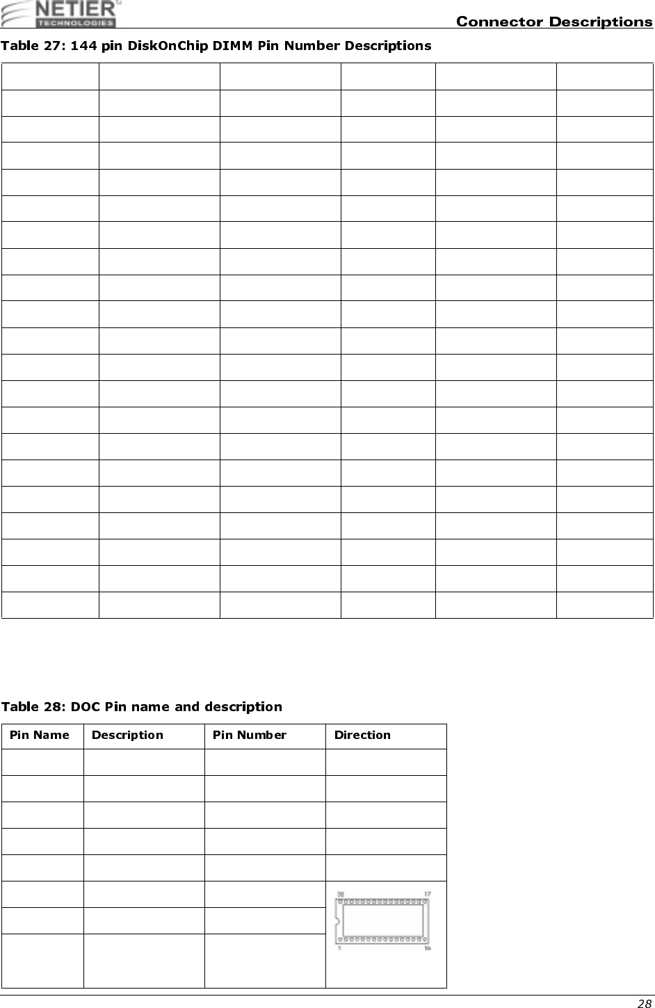
Table 28 list the pin name and description for the DiskOnChip connector.
28 VCC 76 GND 124 No Connect
29 A0 77 No Connect 125 D26
30 A3 78 No Connect 126 No Connect
31 A1 79 No Connect 127 D27
32 A4 80 No Connect 128 No Connect
33 A2 81 VCC 129 VCC
34 A5 82 VCC 130 VCC
35 GND 83 D16 131 D28
36 GND 84 No Connect 132 No Connect
37 D8 85 D17 133 D29
38 No Connect 86 No Connect 134 No Connect
39 D9 87 D18 135 D30
40 No Connect 88 No Connect 136 No Connect
41 D10 89 D19 137 D31
42 No Connect 90 No Connect 138 No Connect
43 D11 91 GND 139 GND
44 No Connect 92 GND 140 GND
45 VCC 93 D20 141 No Connect
46 VCC 94 No Connect 142 No Connect
47 D12 95 D21 143 VCC
48 No Connect 96 No Connect 144 VCC
A0 - A12 Address bus 4-12,23,25-27 Input
D0 - D7 Data bus 13-15,17-21 I/O
CE/ Chip Enable 22 Input
OE/ Output Enable 24 Input
WE/ Write Enable 31 Input
NC Not Connected 1,2,3,28,29,30
VCC Power 32
GND Ground 16
NetXpress™ XL1000/2000 Administrator’s Guide
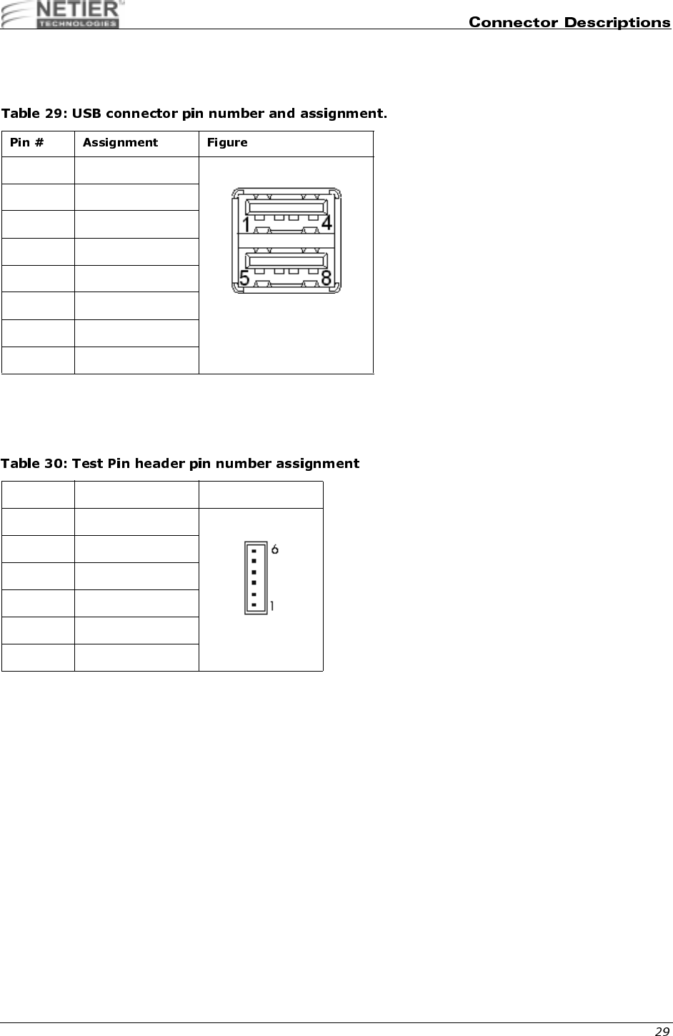
.,%04-$.
Table 29 list the USB connector pin number and assignment.
(<$*1
Table 30 list pin number and assignment for the test pin header.
1+5V
2 USB Port 0 Data -
3 USB Port 0 Data +
4 Ground
5+5V
6 USB Port 1 Data -
7 USB Port 1 Data +
8 Ground
Pin # Assignment Figure
1+5V
2 Ground
3 +3.3V Standby
4+3V
5+2.5V
6+2V
NetXpress™ XL1000/2000 Administrator’s Guide
,
The following charts reflect jumper locations, settings, and their respective functions for the above referenced
motherboard design. The last section reflects a sample listing of Socket-7 CPU's available and all related jumper
settings necessary for those specific CPU's.
• Jumper locations and settings shown here are for reference ONLY.
• Jumper selections shown in this layout are ONLY for "Passive Heat Sink" installation using an AMD K6-
2E (AFZ) low voltage CPU set to 250MHz & 1.8V.
• Set jumper selections for all other CPU's according to charts.
Identify Motherboard
version by these
markings located on the
under-side face of
board.

NetXpress™ XL1000/2000 Administrator’s Guide
,.,5
1.5 OFF OFF ON OFF ON
1.6 OFF ON ON OFF ON
1.7 OFF OFF OFF ON ON
1.8 OFF ON OFF ON ON
1.9OFFOFFONONON
2.0 OFF ON ON ON ON
2.1 ON OFF OFF OFF OFF
2.2 OFF ON OFF OFF OFF
2.3ONONOFFOFFOFF
2.4 OFF OFF ON OFF OFF
2.5 ON OFF ON OFF OFF
2.6 OFF ON ON OFF OFF
2.7ONONONOFFOFF
2.8 OFF OFF OFF ON OFF
2.9ONOFFOFFONOFF
3.0 OFF ON OFF ON OFF
3.1ONONOFFONOFF
3.2OFFOFFONONOFF
3.3 ON OFF ON ON OFF
3.4 OFF ON ON ON OFF
3.5ONONONONOFF
NetXpress™ XL1000/2000 Administrator’s Guide
,.&<$)1
,.,4$)+
1.5 OFF OFF OFF
2.0 ON OFF OFF
2.5 ON ON OFF
3.0 OFF ON OFF
3.5 OFF OFF OFF
4.0 ON OFF ON
4.5 ON ON ON
5.0 OFF ON ON
5.5 OFF OFF ON
6.0 ON OFF OFF
OFF OFF OFF OFF 60 2 30
ON OFF OFF OFF 66.8 2 33.4
OFF ON OFF OFF 70 2 35
ON ON OFF OFF 75 3 25
OFF OFF OFF ON 75 2 37.5
OFF OFF ON OFF 80 3 26.67
ON OFF OFF ON 80 2 40
ON OFF ON OFF 83.3 3 27.76
OFF ON OFF ON 83.3 2 41.55
OFF ON ON OFF 95.25 3 31.75
ON ON ON OFF 100 3 33.33

NetXpress™ XL1000/2000 Administrator’s Guide
9$)%.?@?9A-
,0,$)*
#"$*:+:7:=%
@-
Status
Open (default)
Short (reset state)
CMOS data J24
Clean 2-3
Normal (default) 1-2
Table 36: Address Selection Reserves
0C800H -
0C9FFH R06 R08 VGA
0CC00H -
0CDFFH R06 R07 VGA
0D000H -
0D1FFH R05 R08 OPT. ROM
0D400H -
0D5FFH R05 R07 D.O.C.
0D800H -
0D9FFH R04 R08 BOOT ROM
0DC00H -
0DDFFH R04 R07 BOOT ROM

NetXpress™ XL1000/2000 Administrator’s Guide
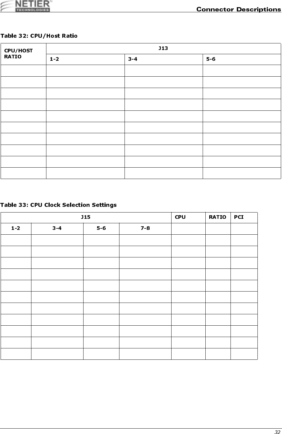
,.$)1:)+
Pentium 100MHz Open Open Open Close Open Open Open
Pentium 120MHz Close Open Open Open Open Open Open
Pentium 133MHz Close Open Open Close Open Open Open
Pentium 150MHz Close Close Open Open Open Open Open
Pentium 166MHz Close Close Open Close Open Open Open
Pentium 200MHz
MMX Open Close Open Close Open Open Open
Pentium 233MHz
MMX Open Open Open Close Open Open Open
AMD K6/
233MHz(AFR) Open Open Open Close Open Open Open
AMD K6/
266MHz(AFR)AM
D K6-2/266MHz
Close Open Close Close Open Open Open
AMD K6-2/
300MHz Open Close open Close Close close Open
AMD K6-2/
333MHz Open Open Open Open Close Close Open
AMD K6-2/
350MHz Open Open Open Close Close Close Open
AMD K6-3/
400MHz Close Open Close Close Close Close Open
AMD K6-3/
450MHz Close Close Close Close Close Close Open

NetXpress™ XL1000/2000 Administrator’s Guide
!"
The following model was selected as an example to assist you in setting up the system BIOS. Please check with your
supplier for additional examples or updated BIOS information.
Netier NetXpress XL thin client BIOS is supplied by Award Software, Inc. AWARD BIOS Flash ROM contains a built-in
setup program that allows you to modify the basic system configuration. This information is stored in the CMOS
chipset RAM, which contains its own battery; therefore, the setup information is retained when the power is turned off.
!;
Power on the computer and immediately press Del to enter BIOS setup.
When the following message appears briefly at the bottom of the screen during the POST (Power On Self Test), press
Del to enter system BIOS setup:
TO ENTER SETUP BEFORE BOOT PRESS the <Del> KEY
If the message disappears before you can press Del then restart the system and attempt to enter system BIOS again.
To restart the system
Turn the power switch OFF and then ON again, or press Ctrl+Alt+Del.
If you do not press the keys to enter BIOS setup at the correct time and the system does not boot,
the error message below will be displayed and you will be asked to select the desired option.
PRESS <F1> TO CONTINUE, <DEL> TO ENTER SETUP
-
Table 39 lists the BIOS setup control keys and their related functions.
NetXpress XL1000 and XL2000
Intel Pentium (MMX) 100/133/166/200/233
XL 1.0
AWARD
Up arrow Move to the previous item
Down arrow Move to the next item
Left arrow Move to the item on the left side
Right arrow Move to the item on the right side
Esc Main Menu—Quit and not save changes into CMOS
Status Page Setup Menu and Option Page Setup Menu—Exit current page and
return to Main Menu
PgUp/+ Increase the numeric value or make changes
PgDn/- Decrease the numeric value or make changes
F1 General help, only for Status Page Setup Menu and Option Page Setup Menu

NetXpress™ XL1000/2000 Administrator’s Guide
.
A description of the selected (highlighted) setup function appears on the bottom of the screen.
&
Press F1 to display a small pop-up help window that describes the setup control key functions and possible uses for
each key. Press F1 or Esc to exit the Help window.
F2/[Shift]+F2 Change color from a total of 16 colors.
F2 to select color forward, [Shift] F2 to select color backward
F3 Reserved
F4 Reserved
F5 Restore the previous CMOS value from CMOS; only for Option Page Setup Menu
F6 Load the default CMOS value from the BIOS default table; only for Option Page
Setup Menu
F7 Load the Setup default; only for Option Page Setup Menu
F8 Reserved
F9 Reserved
F10 Save all CMOS changes; only for Main Menu
NetXpress™ XL1000/2000 Administrator’s Guide
##
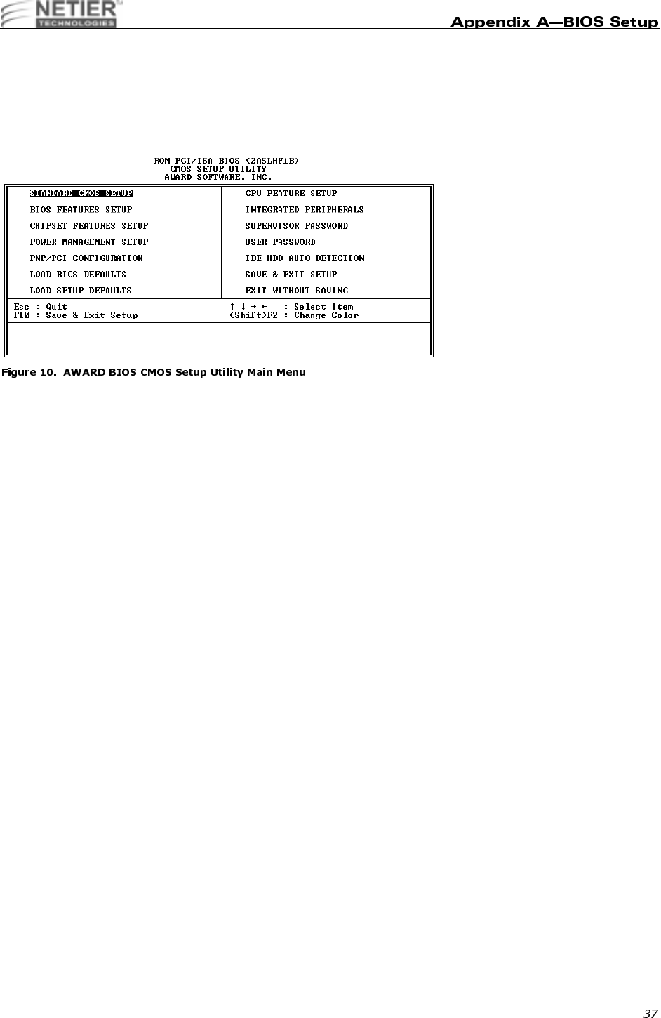
Once you enter the AWARD BIOS CMOS Setup Utility, the Main Menu is displayed. The Main Menu allows you to
select from ten setup functions and two exit choices. Use the arrow keys to select the desired item(s) and press Enter
to accept or enter the sub-menu.
Figure 10 illustrates the AWARD BIOS CMOS Setup Utility Main Menu.
,
This setup page includes all standard compatible BIOS items. See “Standard CMOS Setup Menu” on page 38 for
details.
;
This setup page includes all AWARD special enhanced feature items. See “BIOS Features Setup Menu” on page 41
for details.
,
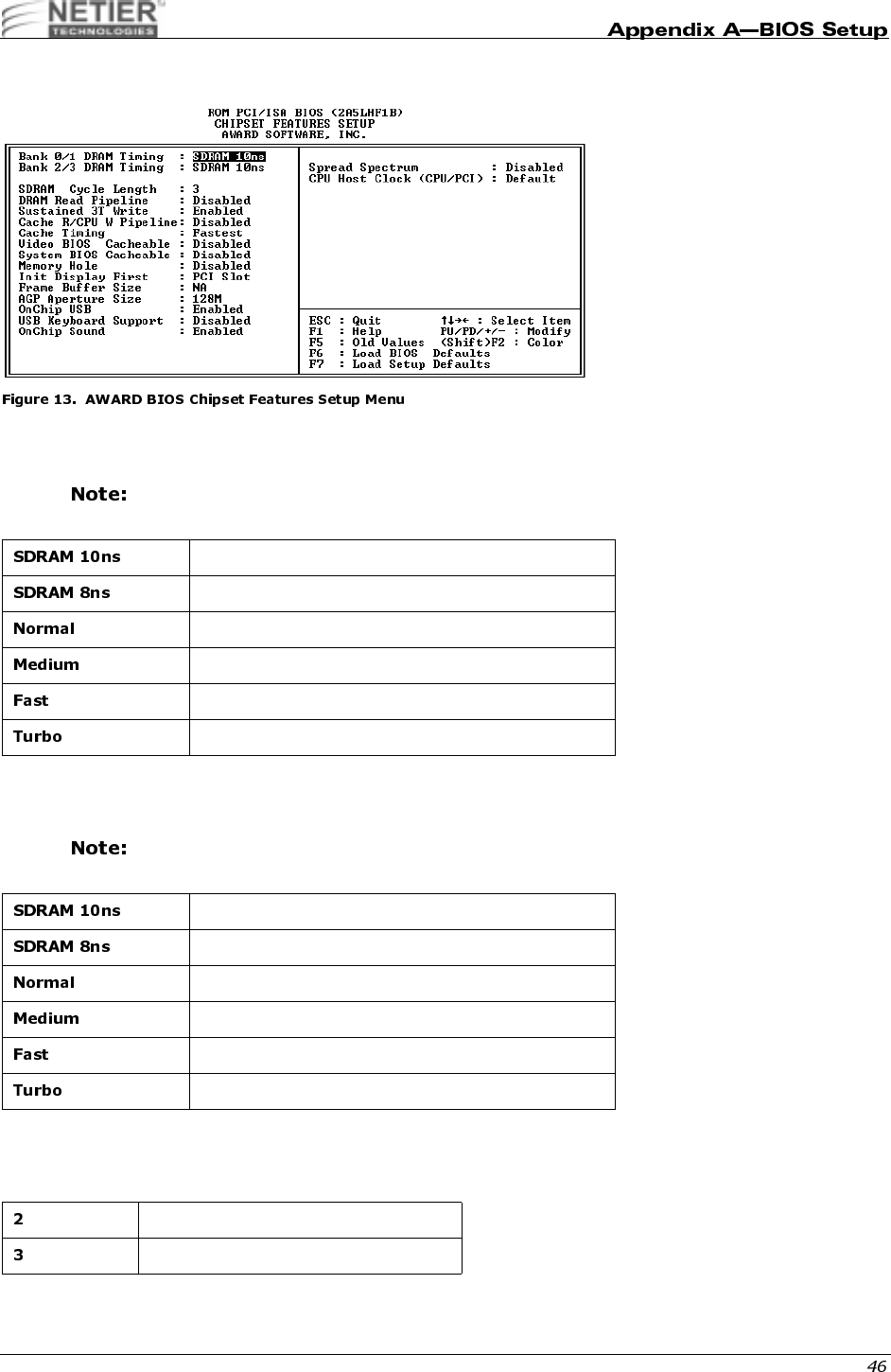
This setup page includes all chipset special feature items. See “Chipset Features Setup Menu” on page 46 for details.
9
The Power Management Setup category determines the system power consumption after selecting various items. See
“Power Management Setup” on page 50 for details.
&,;,
Use the PnP/PCI Configuration category to specify PnP OS or manually configure IRQ/DMA settings. See “PnP/PCI
Configuration” on page 53 for details.
;0
BIOS defaults indicate the system parameter values at which the system would perform at the minimum level.
,.
Use the CPU feature to view the temperature and voltages of the CPU.
0
Setup defaults indicate the system parameter values at which the system would perform at the maximum level.
;
Use the Integrated Peripherals function to enable, disable or configure the on-board devices. See “Integrated
Peripherals” on page 55 for details.
"99
Use this function to change, set, or disable the password. The supervisor password allows you to limit access to both
the system and Setup, or just to Setup. See “Setting the Password” on page 58 for details.
;0!<00#0

NetXpress™ XL1000/2000 Administrator’s Guide
Use the IDE HDD Auto Detection function to automatically detect and configure hard disk parameters. See “IDE HDD
Auto Detection” on page 59 for details.
<009"
This function is the hard disk low level format utility. See “Hard Disk Low Level Format Utility” on page 62 for details.
"!>
Choose this function to save CMOS value changes and exit setup.
!>3"
Choose this function to abandon all CMOS value changes and exit setup.
#$#
The items in the Standard CMOS Setup Menu are divided into 11 categories. Each category includes zero, one, or
more than one setup item. Use the arrow keys to highlight the item, and then press PgUp (PU) or PgDn (PD) to select
the desired for each item.
0
The date format is <day>, <date>, <month>, <year>. Press [F3] to display the calendar.
All Netier Net press thin-client computers are Year 2000 compliant.
(
The time format is <hour> <minute> <second>. The time is calculated based on 24-hour military time. For example, 1
p.m. is 13:00:00 hours.
The day of week, from Sun to Sat, is determined by the BIOS and is read only
The date, from 1 to 31 (or the maximum allowed in the month), can be keyed in using the
numerical key pad
The month, January through December
The year, depending on the current year.
NetXpress™ XL1000/2000 Administrator’s Guide
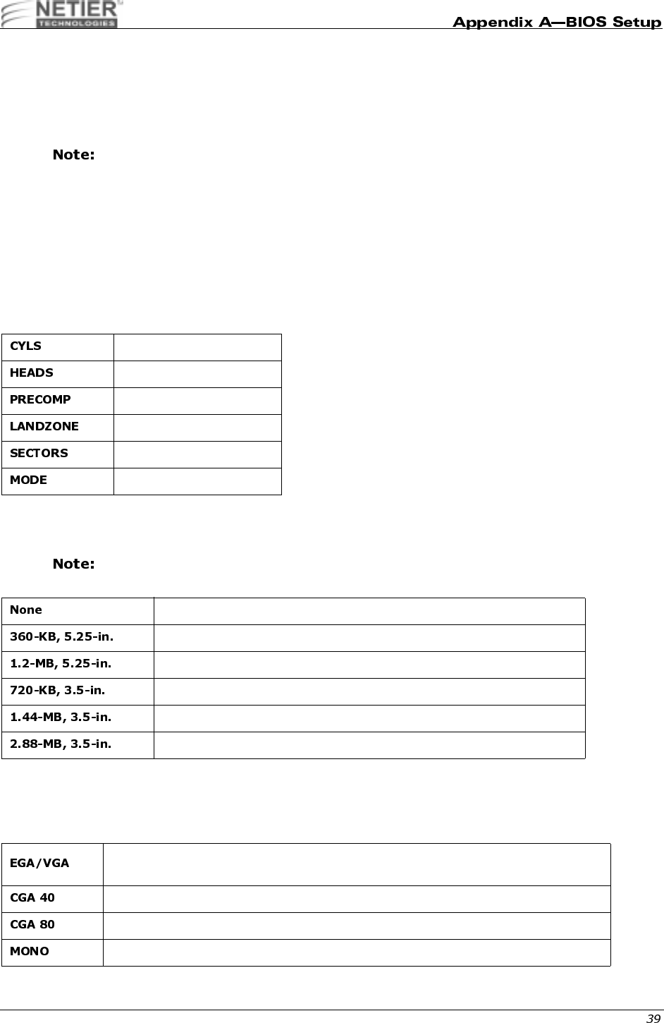
@&"B@&"
These categories identify the type of hard disk drives installed in the computer (C, D, etc.). Forty-five predefined types,
one user definable type, and one automatic type for Normal BIOS are available. Type 1 to Type 45 are predefined.
Type User is user-definable. Type Auto uses your computer’s auto-definition.
Press PgUp/+ or PgDn/− to select a numbered hard disk type, or type the number and press Enter.
Your drive specifications must match those in the drive table. The hard disk will not work properly if
you enter improper information for this category. If your hard disk drive type is not listed in types 1–
45, use
Type User
to manually define your drive type or use type Auto to automatically define your
drive type.
If you select
Type User
, you must enter the related information from the keyboard and press Enter. The required
information should be provided in your hard disk documentation.
• If the HDD is installed, select Auto.
• If a CD-ROM is installed, select Auto.
• If no hard disk or CD-ROM is installed, select None or Auto and press Enter.
0"#&
This category identifies the type of floppy disk drives (A and/or B) installed in the computer.
Select 1.44-MB, 3.5-in. if a floppy disk drive is installed in the system.
5
Use the Video category to select the adapter used for the primary system monitor. This adapter must match your video
display interface and monitor.
Number of cylinders
Number of heads
Write precom
Landing zone
Number of sectors
HDD access mode
No floppy drive installed
5-1/4-inch, PC-type standard drive; 360-KB capacity
5-1/4-inch, AT-type high-density drive; 1.2-MB capacity
3-1/2-inch, double-sided drive; 720-KB capacity
3-1/2-inch, double-sided drive; 1.44-MB capacity
3-1/2-inch, double-sided drive; 2.88-MB capacity
Enhanced Graphics Adapter/Video Graphics Array; for EGA, VGA, SVGA, or PGA
monitor adapters
Color Graphics Adapter; power up in 40-column mode
Color Graphics Adapter; power up in 80-column mode
Monochrome adapter; includes high-resolution monochrome adapters
NetXpress™ XL1000/2000 Administrator’s Guide
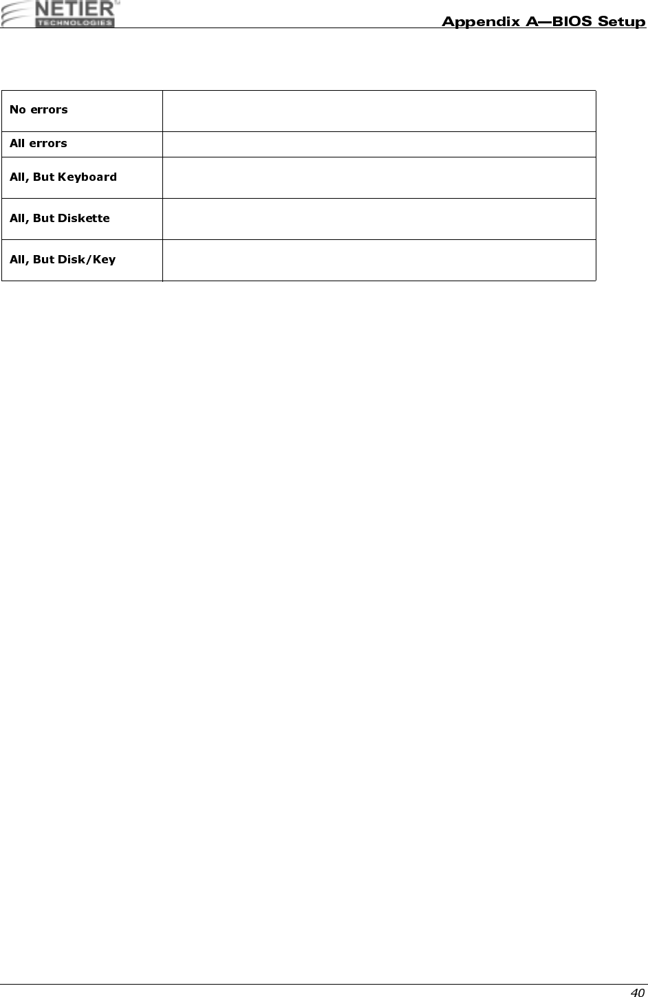
<
The error halt category determines if the computer will stop when an error is detected during power up.
@
This is a display-only category determined by the BIOS Power On Self Test (POST).
BASE MEMORY
The BIOS POST determines the amount of base (or conventional) memory installed in the system. The value of the
base memory is typically 512 KB for systems with 512 KB memory installed on the motherboard, or 640 KB for
systems with 640 KB or more memory installed on the motherboard.
EXTENDED MEMORY
The BIOS determines how much extended memory is present during the POST. Extended memory is the amount of
memory located above 1 MB in the CPU memory address map.
OTHER MEMORY
Other memory refers to the memory located in the 640 KB to 1024 KB address range. Other memory can be used for
different applications. DOS uses this area to load device drivers to keep as much base memory free for application
programs. This memory area is most often used for Shadow RAM.
TOTAL MEMORY
System total memory is the sum of basic memory, extended memory, and other memory.
Whenever the BIOS detects a non-fatal error, the system stops and you will
be prompted.
The system boot stops after any detected error.
The system boot stops after a keyboard error but does not stop after all other
errors.
The system boot does not stop for a disk error but does stop after all other
errors.
The system boot does not stop for a keyboard or disk error but does stop
after all other errors.
NetXpress™ XL1000/2000 Administrator’s Guide
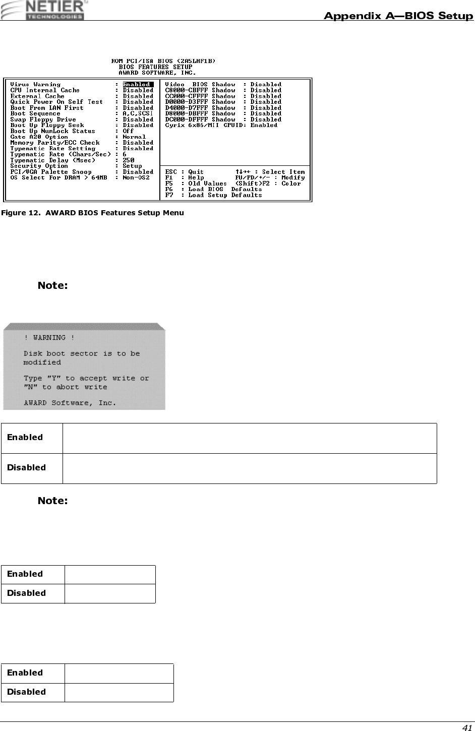
/$#
53
This category flashes on the screen. During and after system boot, any attempt to write to the boot sector or partition
table of the hard disk drive halts the system, and the following error message appears. If this warning appears, run an
anti-virus program to locate the problem.
If you are installing a new operating system when this error message is displayed, you do not need
to run an anti-virus program. Instead, type Y to accept and continue installation.
This function is available only for DOS and other operating systems that do not trap INT13.
,.;,&!>,
These categories accelerate memory access depending on CPU/chipset design. The default value is Enable. If your
CPU does not contain internal cache, the item “CPU Internal Cache” does not appear.
C49(
This category accelerates the Power On Self Test (POST). If Quick Power On Self Test is set to Enable, BIOS
shortens or does not check certain items during the POST.
Activates automatically when the system boots up causing a warning message to appear
when anything attempts to access the boot sector or hard disk partition table.
No warning message appears when anything attempts to access the boot sector or hard
disk partition table.
Enable cache
Disable cache
Enable quick POST
Normal POST
NetXpress™ XL1000/2000 Administrator’s Guide
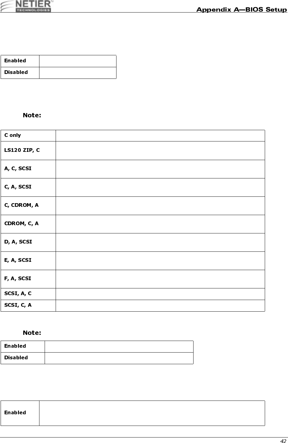
#
Boot from LAN first, if enabled, directs the computer to search the LAN for a DHCP server to opbtain an IP address
and then searches for a PXE server to obtain a 1.44 MB boot file. The computer then runs through its local boot
process using information from the 1.44 MB boot file.
D
This category determines which drive the computer first searches for the disk operating system (e.g., DOS, Windows
3.1, Windows 95, etc.).
The default value is C only.
9@0"
The setting is set to Disabled by default.
.@4
During POST, BIOS determines if the floppy disk drive installed contains 40 or 80 tracks. A 360-KB floppy drive
contains 40 tracks while 720-KB, 1.2-MB, and 1.44-MB contain 80 tracks.
Enable Boot from LAN First
Disable Boot from LAN First
The system only searches the hard disk drive for booting instructions.
The system first searches the LS120 drive then the hard disk drive for booting
instructions.
The system first searches the floppy disk drive then the hard disk drive then the
SCSI Bus.
The system first searches the hard disk drive then the floppy disk drive then the
SCSI Bus.
The system first searches the hard disk drive, then the CD-ROM drive, and then the
floppy disk drive for booting instructions.
The system first searches the CD-ROM drive, then the hard disk drive, and then the
floppy disk drive for booting instructions.
The system first searches the Drive D which is the second active DOS partition then
the floppy disk drive then the SCSI Bus.
The system first searches the Drive E which is the third active DOS partition then
floppy disk drive then the SCSI Bus.
The system first searches the Drive F which is the fourth active DOS partition then
floppy disk drive then the SCSI Bus.
The system first searches the SCSI Bus then the floppy disk drive then Drive C.
The system first searches the SCSI Bus then Drive C then the floppy disk drive.
Enable Floppy Drives A and B Swap function
Disable Floppy Drives A and B Swap function
BIOS searches for the floppy disk drive to determine if it is 40 or 80 tracks. Note that BIOS
cannot determine whether a floppy drive is 720 KB, 1.2 MB, or 1.44 MB because they are
all 80 tracks.

NetXpress™ XL1000/2000 Administrator’s Guide
.4
The default value is On.
6#
This entry allows you to select how gate A20 is handled. Gate A20 is a device used to address memory above 1 MB.
Initially, gate A20 was intended for support. It is more common and much faster for the chipset to provide support for
A20.
@@&!,,,4
This entry allows you to select how the BIOS tests memory parity and ECC (Error Correcting Code) during POST.
The setting is set to Disabled by default.
(@
The typematic rate setting determines the typematic rate.
TYPEMATIC RATE (CHARS/SEC)
When the typematic rate setting is enabled, you can select the rate at which the keys are accelerated.
BIOS will not search for the type of floppy disk drive by track number. Note that no warning
message will appear if the floppy drive installed is 360 KB.
NumLock is on
NumLock is off
Handling gate A20 by keyboard
Handling gate A20 by chipset
The BIOS runs memory test during POST.
The BIOS skips the memory test during POST.
Enable typematic rate and typematic delay programming
Disable typematic rate and typematic delay programming. The system BIOS uses the
default value of these 2 items, and the default is controlled by the keyboard.
6 characters per second
8 characters per second
10 characters per second
12 characters per second
15 characters per second
20 characters per second
24 characters per second
30 characters per second
NetXpress™ XL1000/2000 Administrator’s Guide
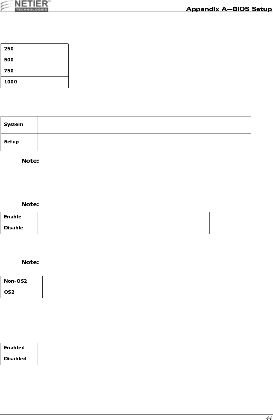
TYPEMATIC DELAY (MSEC)
When the typematic rate setting is enabled, you can select the delay between when the key was first depressed and
when the acceleration begins.
@
The Security Option category allows you to limit access to the system and Setup, or just to Setup.
To disable security, select Password Setting at the Main Menu. You will be asked to enter the
password. Simply press Enter here to disable security. Once the security is disabled, the system will
boot and you can enter Setup freely.
,;&56#
PCI/VGA Palette Snoop determines whether the MPEG ISA/VESA VGA cards are compatible with PCI/VGA.
The setting is set to Disabled by default.
0#E7*
This item allows you to access memory over 64 MB in OS2.
Only select OS2 when you are using OS/2™ as the primary operating system.
5;9
BIOS SHADOW
BIOS Shadow determines whether system BIOS is copied to RAM or the system BIOS is always shadowed to support
LBA HDD.
250 Msec
500 Msec
750 Msec
1000 Msec
The system will not boot, and access to Setup will be denied if the correct password is not
entered at the prompt.
The system will boot, but access to Setup will be denied if the correct password is not
entered at the prompt.
When PCI/VGA works with MPEG ISA/VESA VGA card
When PCI/VGA doesn‘t work with MPEG ISA/VESA card
OS2 cannot access the memory address over 64 MB
OS2 can access the memory address over 64 MB
System shadow is enabled
System shadow is disabled

NetXpress™ XL1000/2000 Administrator’s Guide
59
This setting determines whether video ROM is copied to RAM; however, this setting is optional based on chipset
design. Video Shadow increases the video speed.
C8000–CBFFF SHADOW
CC000–CFFFF SHADOW
D0000–D3FFF SHADOW
D4000–D7FF SHADOW
D8000–DBFFF SHADOW
DC000–DFFFF SHADOW
These categories determine whether optional ROMs are copied to RAM. An example of an optional ROM is one that
supports a SCSI add-on card.
,@>7>/7&;;,.;0
This setting prompts the system to test for the Cyrix 6x86/MII CPU and configure settings as necessary.
Video shadow is enabled
Video shadow is disabled
Optional shadow is enabled
Optional shadow is disabled
Enables Cyrix 6x86/MII CPU
Disables Cyrix 6x86/MII CPU
NetXpress™ XL1000/2000 Administrator’s Guide
#
4&0#(
These catagories allow you to configure DRAM type.
Default memory setting SDRAM 10ns.
4&10#(
These catagories allow you to configure DRAM type.
Default memory setting SDRAM 10ns.
0#,@
This field sets the CAS latency timing.
10ns SDRAM
8ns SDRAM
Normal mode RAM
Medium mode RAM
Fast mode RAM
Turbo mode RAM
10ns SDRAM
8ns SDRAM
Normal mode RAM
Medium mode RAM
Fast mode RAM
Turbo mode RAM
Sets SDRAM Cycle length to 2
Sets SDRAM Cycle length to 3

NetXpress™ XL1000/2000 Administrator’s Guide
0#
This category allows you to enable and disable DRAM Read Pipeline.
1(3
You may enable this field when pipelined burst synchronous SRAM (PBSRAM) cache memory is installed. It enables
sustained three-cycle write access for PBSRAM access at 66 or 75 MHz.
,&,.3&
This category allows you to enable or disable Cache Rd+CPU Wt Pipeline.
,(
For a secondary cache of one bank, select Faster. For a secondary cache of two banks, select Fastest.
5;,
Selecting Enabled allows caching of the video BIOS ROM at C0000h to C7FFFh, resulting in better video
performance. However, if any program writes to this memory area, a system error may result.
@;,
Selecting Enabled allows caching of the system BIOS ROM at F0000h-FFFFFh, resulting in better system
performance. However, if any program writes to this memory area, a system error may result.
@<+ #F
Some ISA card memory must be mapped into the system memory address between 15 MB~16 MB to improve
performance.
Enables DRAM Read Pipeline.
Disables DRAM Read Pipeline
Enable Sustained 3T Write
Disable Sustained 3T Write
Enables Cache Rd+CPU Wt Pipeline
Disables Cache Rd+CPU Wt Pipeline
Enable Video BIOS Caching
Disable Video BIOS Caching
Enable System BIOS Caching
Disable System BIOS Caching
Memory address 15~16 MB is reserved for the user.
Memory address 15~16 MB is reserved for ISA cards.
The system can access memory address 0~15 MB only.

NetXpress™ XL1000/2000 Administrator’s Guide
;;(0@
G
#6#G
Select the size of the Accelerated Graphics Port (AGP) aperture. The aperture is a portion of the PCI memory address
range dedicated for graphics memory address space. Host cycles that hit the aperture range are forwarded to the AGP
without any translation. See www.agpforum.org for APG information. You can configure the size of the AGP aperture
to 4, 8, 16, 32,64,128MB.
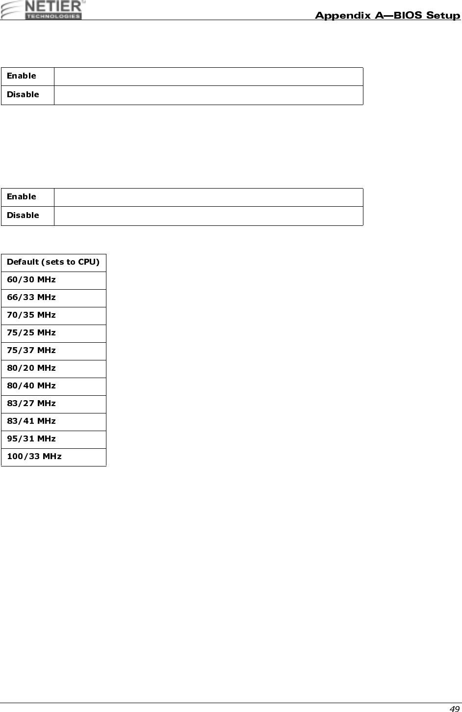
,.
This category allows you to enable or disable onboard USB ports.
,
Initializes the PCI video display before
initializing any other display device on the
system. The PCI display becomes the
primary display.
Initializes the AGP video display before
initializing any other display device on the
system. The AGP display becomes the
primary display.
Reserves 8MB of main system memory for on-board AGP video
Reserves 4MB of main system memory for on-board AGP video
Reserves 2MB of main system memory for on-board AGP video
Does not reserve any main system memory for video
Enables OnChip USB
Disables OnChip USB
Enables OnChip Sound
Disables OnChip Sound
NetXpress™ XL1000/2000 Administrator’s Guide
.H@
Select Enabled if your system contains a Universal Serial Bus (USB) controller and you have a USB keyboard.
.
When the system clock generator pulses, the extreme values of the pulse generate excess EMI. Enabling pulse
spectrum spread modulation changes the extreme values from spikes to flat curves, thus reducing EMI. This benefit
may in some cases be outweighed by problems with timing-critical devices, such as a clock-sensitive SCSI device. We
recommend you keep this setting at the Disabled default value.
,.<,4%,.&,;-
Enables USB keyboard
Disables USB keyboard
Enables Spread Spectrum
Disables Spread Spectrum
NetXpress™ XL1000/2000 Administrator’s Guide
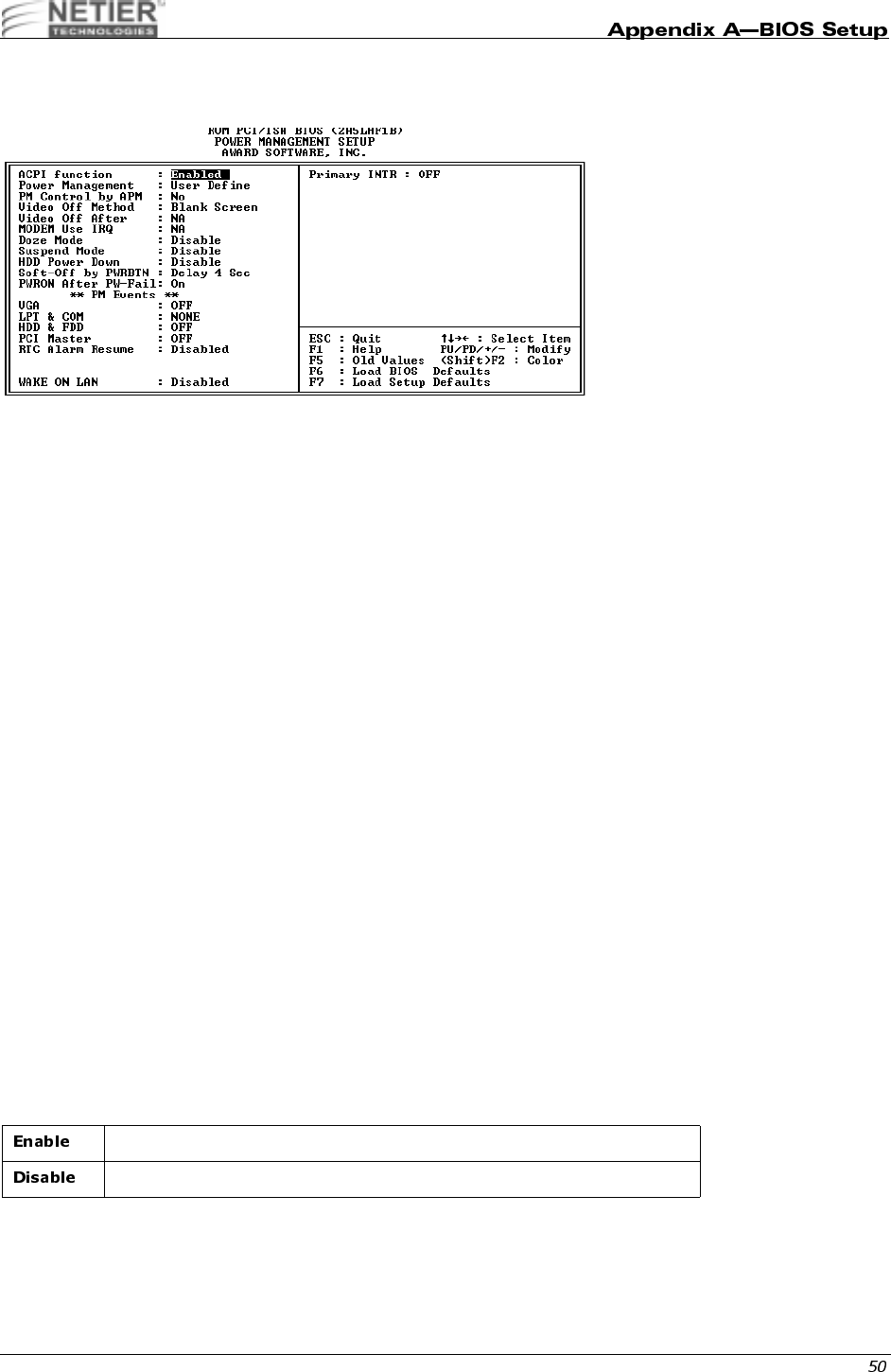
0#
The Power Management Setup screen appears on your screen similar to the following illustration:
#,;
Advanced Configuration and Power Interface (ACPI) determines whether the operating system controls the power
management and Plug and Play functions of the system. ACPI defines a flexible and extensible interface that allows
system designers to select appropriate cost/feature trade-offs for power management. The interface enables new
power management technology to evolve independently in operating systems and hardware while ensuring that they
continue to work together. For more information on ACPI, please refer to these two Internet sites:
• http://www.teleport.com/~acpi/
• http://www.microsoft.com/hwdev/desinit/acpifaq2.htm
WHY IS ACPI IMPORTANT?
Changing from Advanced Power Management (APM) and Plug and Play (PnP) to ACPI offers many benefits including
the following:
• A cooperative "Plug and Play" environment for devices and power management for desktops, notebooks, and
servers
• An open Operating System Architecture that allows the development of ACPI for non-Microsoft operating
systems. This O/S also lets ACPI-compliant operating systems running on non-standard hardware use the
ACPI interface.
• New opportunities for product differentiation
• Developer-defined control methods using the ACPI language
• ACPI support is required for NT 5.0, Windows/PC 97& 98, Server 97& 98, and OnNow Certification. Older
versions of NT do not have any power management support. ACPI-compliant systems running NT can take
full advantage of power savings through ACPI power management.
Phoenix has an ACPI compliant BIOS, which the NT 5.0 and Win 98 development teams at Microsoft have been using
for several months. The ACPI hardware interface provides two types of functionality to the operating system that
previously resided in the BIOS:
• Control and detection of system control events using a normal interrupt called System Control Interrupt (SCI)
rather than System Management Interrupt (SMI)
• Control of the system power state (http://www.phoenix.com/platform/acpi.html, 1998)
Enables ACPI
Disables ACPI
NetXpress™ XL1000/2000 Administrator’s Guide
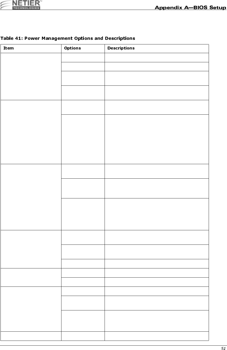
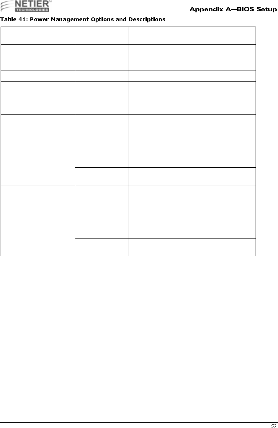
9
This category determines the system power consumption level after selecting the items below. The default value is
Disable. Table 41 describes each item’s options.
Power Management 1. Disabled Global Power Management will be disabled
2. User Define Users can configure their own power management
3. Min Saving Pre-defined timer values are used such that all
timers use the MAX values
4. Max Saving Pre-defined timer values are used such that all
timers use the MIN values
PM Control by APM 1. No The system BIOS ignores APM when performing
system power management
2. Yes The system BIOS waits for a prompt from APM
before entering any power management mode.
Note: If APM is installed and a task is running,
even if the timer is timed out, APM does not prompt
the BIOS to put the system into any power saving
mode.
Note: If APM is not installed, this option has no
effect.
Video Off Method 1. Blank Screen The system BIOS only blanks the screen when
disabling video
2. V/H SYNC +
Blank In addition to (1), the BIOS also turns off the V-
SYNC & H-SYNC signals from the VGA card to the
monitor
3. DPMS Support This function is only enabled on VGA cards that
support the DPM function, which initializes the
display’s power saving management signaling
Note: Green monitors detect the V/H SYNC signals
and turn off the electron gun.
Video Off After Suspend Monitor powers down when the system enters
Suspend mode
Doze Monitor powers down when the system enters
Doze mode.
NA Monitor is never powered down by the BIOS.
MODEM Use IRQ NA A modem card is not installed
3,4,5,7,9,10, 11 Manually input the modem card’s IRQ.
Doze Mode Disabled System never enter doze mode (low-power saving)
10,20,30,40
seconds System enters doze mode after specified time.
1,2,4,6,8,10,20,
30,40 minutes
1 hour
System enters doze mode after specified time.
Suspend Mode Disabled System never enters suspend.
NetXpress™ XL1000/2000 Administrator’s Guide
10,20,30,40
seconds System enters supspend (high-power saving)
mode after specified time.
1,2,4,6,8,10,20,
30,40 minutes
1 hour
System enters supspend (high-power saving)
mode after specified time.
HDD Power Down 1. Disable The HDD motor will not be powered down
2. 1~15 min. Defines the continuous HDD idle time before the
HDD enters the power saving mode (motor off)
Note: When the HDD is in the power saving mode,
the HDD is initialized upon future access.
Soft-Off by PWRBTN 1. Instant-Off The system powers down immediately after the
power button is pushed.
2. Delay 4 Sec The system powers down 4 seconds after the
power button is pushed.
PWRON After PW-FAIL 1. Off The system will not automatically turn on after a
power failure.
2. On The system automatically powers up after a power
failure.
VGA, LPT & COM, HDD &
FDD, DMA/MASTER,
MODEM RING RESUME,
RTC ALARM RESUME,
PRIMARY INTR
1. Off The specified event’s activity does not affect the
PM timers
2. On The specified event’s activity causes the PM
Timers to be reloaded and activate the inactive
device.
Wake on LAN Disabled System will not turn on with any network traffic.
Enabled System will turn on when a Magic packet is
received.
NetXpress™ XL1000/2000 Administrator’s Guide
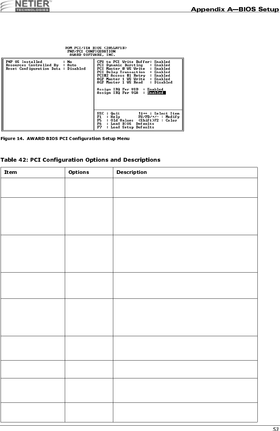
1
You can manually configure the PCI device’s IRQ settings. The following pages describe each item’s options and
explain the meaning of each option.
Table 42 describes each item’s options and explains the meaning of each option.
PNP OS Installed Yes
No
Select Yes if the system operating environment is Plug-
and-Play aware (e.g., Windows 95).
Resources Controlled
By Auto
Manual
By The Plug and Play AwardBIOS can automatically
configure all the boot and Plug and Play-compatible
devices. If you select Auto, all the interrupt request (IRQ)
and DMA assignment fields disappear, as the BIOS
automatically assigns them.
Reset Configuration
Data Enable
Disable
Normally, you leave this field Disabled. Select Enabled to
reset Extended System Configuration Data (ESCD) when
you exit Setup if you have installed a new add-on and the
system reconfiguration has caused such a serious conflict
that the operating system cannot boot.
IRQ3~15, DMA 0~7
assign to Legacy ISA
PCI/ISA PnP
Assign IRQ or DMA channel to ISA bus device only
Assign IRQ or DMA channel can be resourced for PCI and
ISA device
CPU to PCI Write Buffer Enable /Disable When Enabled, the CPU can write up to four dwords of
data to the PCI write buffer before the CPU must wait for
the PCI bus cycles to finish. When Disabled, the CPU
must wait after each write cycle until the PCI bus signals
that it is ready to receive more data.
PCI Dynamic Bursting Enable /Disable When Enabled, every write transaction goes to the write
buffer. Burstable transactions then burst on the PCI bus
and non-burstable transactions do not.
PCI Master 0 WS Write Enable /Disable When Enabled, writes to the PCI bus are executed with
zero wait states.
PCI Delay Transaction Enable /Disable The chipset has an embedded 32-bit posted write buffer to
support delay transactions cycles. Select Enabled to
support compliance with PCI specification version 2.1.
PCI #2 Access #1 Retry Enable /Disable Select Enable to enable PCI #2 Access #1 Retry.
Select Disable to disable PCI #2 Access #1 Retry.

NetXpress™ XL1000/2000 Administrator’s Guide
AGP Master 1 WS Write Enable /Disable Select Enable to enable AGP Master 1 WS Write.
Select Disable to disable AGP Master 1 WS Write.
AGP Master 1 WS
Read Enable /Disable Select Enable to enable AGP Master 1 WS Read.
Select Disable to disable AGP Master 1 WS Read.
PCI IRQ Activated By Edge/Level Leave the IRQ trigger set at Level unless the PCI device
assigned to the interrupt specifies Edge-triggered
interrupts.
Assign IRQ for USB Enable /Disable The BIOS assigns an IRQ for the USB port. The operating
system determines USB resources.
Assign IRQ for VGA Enable /Disable The BIOS assigns an IRQ for Video. The operating system
determines Video resources.

NetXpress™ XL1000/2000 Administrator’s Guide
',;0!,
Use this category to assign an active or non-active status to the primary motherboard IDE interface.
,;0!,
;0!
The onboard IDE drive interfaces supports IDE prefetching, for faster drive accesses. If you install a primary and/or
secondary add-in IDE interface, set this field to Disabled if the interface does not support prefetching.
;0!<004
Use this category to assign the block transfer function (the size per block is defined by your hard disk) of the primary
IDE interface on the motherboard to achieve the best hard disk performance.
Enable the onboard primary IDE channel
Disable the onboard primary IDE channel
Enable on-board secondary IDE channel
Disable on-board secondary IDE channel
Enable IDE PreFetch Mode
Disable IDE PreFetch Mode
Enable the block transfer function
Disable the block transfer function

NetXpress™ XL1000/2000 Administrator’s Guide
;0!@&@&";
Use these settings to assign the Programming I/O mode of the primary and secondary IDE interfaces on the mother
board. The correct settings improve hard disk performance.
;0!@&@&".0#
UDMA (Ultra DMA) is a DMA data transfer protocol that utilizes ATA commands and the ATA bus to allow DMA
commands to transfer data at a maximum burst rate of 33 MB/s. When you select Auto in the four IDE UDMA fields (for
each of up to four IDE devices that the internal PCI IDE interface supports), the system automatically determines the
optimal data transfer rate for each IDE device.
04,
Enable/Disable Disk On Chip (DOC) socket.
0,,
Use this category assign the motherboard (floppy disk controller) FDC interface as active or non-active.
The system automatically detect the best type for your hard disk.
Assign the hard disk PIO setting to Mode 0 (Max. access time = 600 ns, Max. speed = 3.3
MB/sec.)
Assign the hard disk PIO setting to Mode 1 (Max. access time = 383 ns, Max. speed = 5.2
MB/sec.)
Assign the hard disk PIO setting to Mode 2 (Max. access time = 240 ns, Max. speed = 8.3
MB/sec.)
Assign the hard disk PIO setting to Mode 3 (Max. access time = 180 ns, Max. speed = 11.1
MB/sec.)
Assign the hard disk PIO setting to Mode 4 (Max. access time = 120 ns, Max. speed = 16.6
MB/sec.)
Disable the IDE Primary/Secondary
Master/Slave UDMA
Enable the IDE Primary/Secondary
Master/Slave UDMA
Enable DOC
Disable DOC
Enable mother board FDC interface
Disable mother board FDC interface

NetXpress™ XL1000/2000 Administrator’s Guide
&
Use these categories to assign the I/O address and interrupt request channel of the RS232 ports on the mother board.
.#(
Use these categories to assign the operation mode of the RS232 ports on the mother board.
.#(&;0>
Use these categories to assign the duplex mode of the serial IR ports on the mother board.
Use this category to assign the I/O address and interrupt request channel for the parallel port on the mother board.
Use this category to assign the working mode of the parallel port on the mother board.
I/O address=3F8h, IRQ channel=4 (COM1)
I/O address=2F8h, IRQ channel=3 (COM2)
I/O address=3E8h, IRQ channel=4 (COM3)
I/O address=2E8h, IRQ channel=3 (COM4)
The system automatically assigns the viable I/O address and IRQ channel to
your RS232 ports on the mother board.
Disables the RS232 function of the mother board.
RS232 will work in FIFO standard mode
RS232 will work in Half Phase Serial Infrared mode
RS232 will work in Amplitude Shift Keyed Infrared mode
Serial IR port will work in half duplex mode
Serial IR port will work in full duplex mode
2-pin One transmit One receive
4-pin Two transmit Two receive
I/O address = 378h, IRQ channel = 7
I/O address = 278h, IRQ channel = 5
I/O address = 3BCh, IRQ channel = 7
Disable the parallel function on the mother board
Parallel port will work in SPP (standard parallel port) mode
Parallel port will work in EPP (enhanced parallel port) mode
Parallel port will work in ECP (extended capabilities port) mode
Parallel port will auto-detect the parallel device for working in EPP or ECP mode
NetXpress™ XL1000/2000 Administrator’s Guide
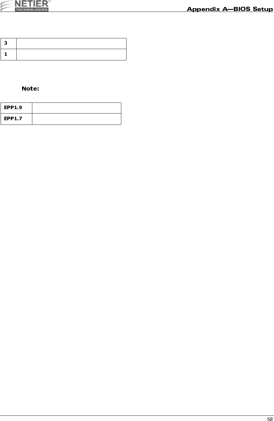
!,.0#
Use this category to assign the DMA (direct memory access) channel for the ECP device used.
!(@
Use this category to assign the IEEE standard version for the EPP device used.
Please refer to your printer documentation when selecting EPP type.
0
When you select this function, the following message appears at the center of the screen to assist you in creating a
password.
ENTER PASSWORD:
Type the password, up to eight characters, and press Enter. The password typed clears any previously entered
password from CMOS memory. You will be asked to confirm the password. Type the password again and press Enter.
You may also press Esc to abort the selection and not enter a password.
To disable the password, press Enter when you are prompted to enter password. A message confirms the password
being disabled. Once the password is disabled, the system boots and you can enter Setup freely.
PASSWORD DISABLED.
If you select System from the BIOS Features Setup Menu Security option, you are prompted for the password each
time the system is rebooted or each time you try to enter Setup. If you select Setup from the BIOS Features Setup
Menu Security option, you are prompted for the password only when entering Setup.
The system allows you to modify each item when you use the supervisor password to enter the CMOS setup screen.
The system only allows you to modify the user password setting when you use your user password to enter the CMOS
setup screen.
DMA 3 is used by the ECP device
DMA 1 is used by the ECP device
Version 1.9 (new version)
Version 1.7 (old version)
NetXpress™ XL1000/2000 Administrator’s Guide
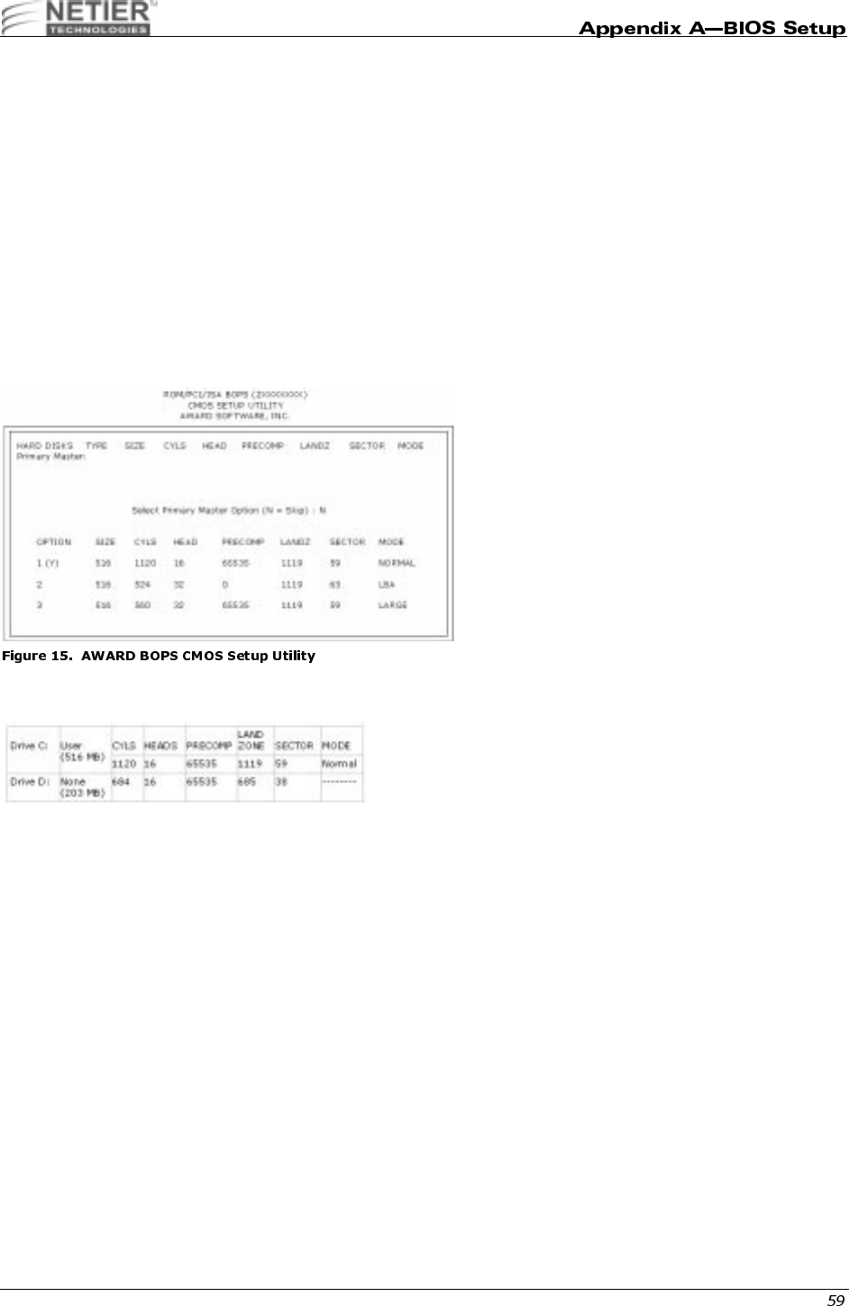
" ""2"
The Enhanced IDE feature is provided in all AWARD BIOS. Below is a brief description of this feature.
F,
AUTO-DETECTION
BIOS setup displays all modes supported by the HDD, including:
•Normal
•LBA
• Large
If the HDD does not support the LBA mode, no LBA option is shown. If the number of cylinders is less than or equal to
1024, no Large option is shown.
Select the appropriate mode. An illustration of the AWARD CMOS setup utility is provided below for your convenience.
STANDARD CMOS SETUP
When the HDD type is User, the Mode field becomes available to select the HDD mode.

NetXpress™ XL1000/2000 Administrator’s Guide
F<00
The AWARD BIOS supports the following three HDD modes:
•Normal
•LBA
• Large
NORMAL MODE
General access mode -the maximum number of cylinders, head & sectors for NORMAL mode are 1024, 16 and 63.
If the HDD is set to Normal mode, the maximum accessible HDD size is 528 MB Megabytes, even though its physical
capacity may be larger.
LBA (LOGICAL BLOCK ADDRESSING) MODE
LAB represents a new HDD access method to overcome the 528-MB bottleneck. The number of cylinders, heads, and
sectors that appear in setup may not be the number physically contained in the HDD.
During HDD access, the IDE controller transforms the logical address described by the sector, head, and cylinder
number into its own physical address inside the HDD.
The maximum HDD size supported by LBA mode is 8.4 GB, which is obtained through the following formula:
X No Cylinder (1024)
X No. Head (16)
X No. Sector (63)
No. per Sector (512)
528 Megabytes
X No Cylinder (1024)
X No. Head (255)
X No. Sector (63)
No. per Sector (512)
8.4 Gigabytes
NetXpress™ XL1000/2000 Administrator’s Guide
LARGE MODE
AWARD Software supports extended HDD access mode.
Some IDE HDDs contain more than 1024 cylinders, and users may not want to select LBA mode. AWARD BIOS
provides an alternative to support these HDDs.
Large Mode Example
BIOS tells the operating system that the number of cylinders is less than 1024 divided by 2. At the same time, the
number of heads is multiplied by 2. A reverse transformation process occurs inside INT13h to access the right HDD
address.
Maximum HDD Size
1F4
To support either the HDD LBA or Large mode, some modes must be software involved. This software is located in the
AWARD HDD Service Routine (INT 13h). It may be impossible to access HDD in LBA (Large) mode if your operating
system or a running application program replaces the entire INT 13h.
1120 16 59 Normal
560 32 59 Large
X No Cylinder (1024)
X No. Head (32)
X No. Sector (63)
No. per Sector (512)
1.0 Gigabyte

NetXpress™ XL1000/2000 Administrator’s Guide
"0!,
The AWARD Low-Level-Format utility is a tool designed to save time formatting your hard disk. The utility
automatically checks the selected drive’s necessary information. The utility also searches for bad tracks and lists them
for your reference.
,H@
Use the Up and Down arrow keys to select from the items displayed on the upper portion of the screen. Press Enter to
accept the selection. Press Esc to abort the selection or exit the utility.
0"
Select from installed hard disk drive C or D. The drive(s) the utility automatically detects is listed at the bottom of the
screen.
(4
AUTO SCAN BAD TRACK
This utility automatically scans bad tracks and lists the bad tracks in the window on the right-hand side of the screen.
ADD BAD TRACK
Type bad track information in the window on the right-hand side of the screen.
MODIFY BAD TRACK
Modify user-input bad track information in the window on the right-hand side of the screen.
DELETE BAD TRACK
Delete user-input bad track information in the window on the right-hand side of the screen.
CLEAR BAD TRACK TABLE
Clear the entire bad track list in the window on the right- hand side of the screen.
INTERLEAVE
Select the interleave number of the hard disk drive on which you want to perform a low-level format. Select from 1 to 8.
Check the accompanying hard disk documentation for the correct interleave number, or select 0 for automatic
detection by the utility.
AUTO SCAN BAD TRACK
This feature allows the utility to scan first, then format by each track.
START
Press Y to start the low-level format.
03$/
If, after you have made changes to the CMOS values and the system cannot boot with the CMOS values selected in
Setup, restart the system by turning it off then on. You may also restart by simultaneously pressing Ctrl, Alt, and Del.
While the system is restarting, immediately press Insert to load the default CMOS BIOS value for boot up.

NetXpress™ XL1000/2000 Administrator’s Guide
/$45$#
When the BIOS encounters an error that requires the user to correct something, either a beep code will sound or a
message will be displayed in a box in the middle of the screen. The message PRESS F1 TO CONTINUE OR DEL TO
ENTER SETUP will be shown in the information box at the bottom.
(
There are two types of beep codes in the AWARD BIOS. One code indicates a video error has occurred and the BIOS
cannot initialize the video screen to display any additional information. This beep code consists of a single long beep
followed by three short beeps. The other code indicates a DRAM error has occurred. This beep code consists of a
single, long, repeated beep.
!
One or more of the following error messages may be displayed if the BIOS detects an error during the POST. The
following list contains error messages for all AWARD BIOS:
CMOS BATTERY HAS FAILED
The CMOS battery is no longer functional and should be replaced.
CMOS CHECKSUM ERROR
The CMOS checksum is incorrect. This can indicate the CMOS has become corrupt. Or, this error can be caused by a
weak battery. Check the battery and replace if necessary.
DISPLAY SWITCH IS SET INCORRECTLY
The display switch on the motherboard can be set to either monochrome or color. This indicates the switch is set to a
different setting than indicated in Setup. Determine which setting is correct, and either turn off the system and change
the jumper, or enter Setup and change the VIDEO selection.
FLOPPY DISK(S) fail (80)
Unable to reset floppy subsystem.
FLOPPY DISK(S) fail (40)
Floppy Type does not match.
HARD DISK(S) fail (80)
HDD reset failed.
HARD DISK(S) fail (40)
HDD controller diagnostics failed.
HARD DISK(S) fail (20)
HDD initialization error.
HARD DISK(S) fail (10)
Unable to recalibrate fixed disk.
HARD DISK(S) fail (08)
Sector verify failed.
Keyboard is locked out–Unlock the key
BIOS detected the keyboard is locked. P17 of the keyboard controller is pulled low.
Keyboard error or no keyboard present
Cannot initialize the keyboard. Make sure the keyboard is attached correctly and no keys are being pressed during the
boot.
Manufacturing POST loop
The system will repeat the POST procedure infinitely while the P15 of the keyboard controller is pulled low. This is also
used for M/B burn in test.
BIOS ROM checksum error–System halted
The checksum of ROM address F0000H-FFFFFH is bad.
Memory test fail
BIOS reports the memory test failed if errors occurred during the onboard memory test.

NetXpress™ XL1000/2000 Administrator’s Guide
"!#$%%%&'(#
)67#84$#"0"$
'777
The DiskOnChip 2000 is a single-chip Flash Disk designed to plug into a standard 32-pin Flash EPROM socket. The
DiskOnChip 2000 should be mapped to an 8-Kb window in the system BIOS expansion address space, which is
usually located in address 0C8000H to 0E0000H.
The DiskOnChip 2000 contains a built-in copy of the M-Systems industry-standard TrueFFS software, which allows the
DiskOnChip to operate as a standard disk drive. The DiskOnChip 2000 can also contain the operating system,
allowing BOOT capability in systems without a hard disk. See “Configuring the DiskOnChip 2000 as the First Drive” on
page 66 for more information.
The DiskOnChip is a self-contained device. The installation of the DiskOnChip does not require any software
installation. The design of the DiskOnChip allows for full upward and downward compatibility. While available today in
capacities of 8 to 288 MB, future DiskOnChip devices with higher densities will be fully compatible with standard
DiskOnChip sockets. The basic design of the DiskOnChip actually supports an unlimited capacity.
$"$
;04,
Caution: Always unplug the NetXpress Thin Client from the power supply before conducting any internal
work.
When installing or removing the DiskOnChip, be sure to first touch a grounded surface to discharge any static
electricity from your body.
To install the DiskOnChip:
1Align pin 1 on the DiskOnChip with pin 1 of socket.
2Push the DiskOnChip into the socket carefully until it is fully seated.
Ensure the DiskOnChip is installed securely and there are no bent pins.
Caution: The DiskOnChip may be permanently damaged if installed incorrectly.
INSTALLING THE DOC AS A HARD DISK
To install the DiskOnChip as drive C on a system without a hard disk:
1Set the drive C CMOS setup of to “not installed” (no physical magnetic disk is installed), and reboot the
computer.
The DiskOnChip 2000 installs as drive C. The DiskOnChip must be formatted with the System files
in order for it to BOOT. See “Configuring the DiskOnChip 2000 as the BOOT Device” on page 65 for
more information.
If a hard drive is installed in the system, the DiskOnChip either does not operate or is identified as
the primary hard drive. The DOC must be enabled under
Integrated Periperals
in the BIOS.
To install the DiskOnChip as drive D on a system with a hard disk, simply reboot the system and the
DiskOnChip will be installed as drive D.
To install the DiskOnChip as Drive C on a system with a hard disk, see “Configuring the DiskOnChip
2000 as the First Drive” on page 66.

NetXpress™ XL1000/2000 Administrator’s Guide
,04,(0"
To configure the DiskOnChip as the BOOT device, the operating system files must be copied into the DiskOnChip.
Copying the operating system files into the DiskOnChip is performed like in any other hard disk. The following steps
describe a typical initialization process:
1Set up the DiskOnChip as a regular drive in your system (not a BOOT drive).
2Install a bootable floppy diskette in drive A and BOOT the system.
3At the DOS prompt, type SYS C: to transfer the DOS system files to the DiskOnChip (assuming the DiskOn-
Chip is installed as drive C).
4Copy all necessary files into the DiskOnChip.
5Remove the floppy diskette and reboot the system. The system will BOOT from the DiskOnChip, and will
allow you to run and access any files that have been copied into the DiskOnChip.
The hard drive must be set on the 2nd IDE controller.
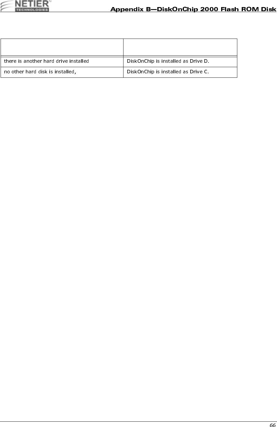
NetXpress™ XL1000/2000 Administrator’s Guide
,04,0"
The DiskOnChip can be configured to be installed as the last drive (default) or as the first drive in the system.
When configured as the first drive, the DiskOnChip is always installed as drive C.
The DiskOnChip is shipped from the factory configured to be installed as the last drive. To configure the DiskOnChip to
be installed as the first drive, use the steps below:
1BOOT the system and make sure the DiskOnChip is installed correctly as drive D.
2At the DOS prompt type: DUPDATE D:/FIRST /S:DOC105.EXB.
3After re-booting the system, the DiskOnChip appears as C:.
If the DiskOnChip 2000 is installed as the last
drive and ... then...
NetXpress™ XL1000/2000 Administrator’s Guide
F 049.
DFORMAT
Before TrueFFS can access a flash media, the media must be formatted, just as a floppy disk must be formatted
before use. Formatting initializes the media and writes a new and empty DOS file system to the media. When
formatting is complete, the media contains only a root directory.
The Flash Disk is fully tested and formatted before the product is shipped, but it can be formatted more than once.
Each time it is formatted, all data on the media is destroyed. When reformatting, the boot-image is retained by default.
The DFORMAT syntax is:
Usage: DFORMAT {drive-letter/WIN:segment} [/SIZE:size] [/USE:nnn] [/LABEL:label] [/DOSVER:n] [/SPARE:n] [/Y]
The DFORMAT options are:
Example 1: DFORMAT C:
Formats the Flash Disk used as Drive C.
Example 2: DFORMAT /WIN:D000
Formats the Flash Disk located at memory address hex D000. If any other hard disk is present in the system, the Flash
Disk is identified as drive D:
CONFIGURING THE DISKONCHIP AS A BOOTABLE DISK
The Flash Disk fully supports the BOOT capability. For the Flash Disk to be bootable, it should be DOS formatted as
bootable, like any floppy or hard disk required to be bootable.
Example 1: SYS D:
Changes the disk into a bootable medium, assuming the Flash Disk is disk D:.
driver-letter DOS driver letter of the TrueFFS drive.
/WIN:Segment Memory address in which the DiskOnChip is located. Use either
this flag or the driver-letter flag.
/SIZE:size The size of the flash media to be formatted (including the install
partition). By default the entire media is formatted by DFORMAT.
This option limits the formatted size.
/USE:nnn Percentage of available space on the flash media to be used for
file storage. nnn can be any number from 1 to 100. Default is 99
(99%).
The value of this option may affect the write performance of
TrueFFS.
/DOSVER:dos-major-version Format for a target system running the specified DOS version.
The default is the current DOS version (the one on which
DFORMAT is executed). For example, /DOSVER:3 formats for
DOS 3.X. Valid values are 1 to 6.
/SPARE:n Number of spare units. Default is 1. A value 0 selects a WORM
(Write Once Read Many).
/Y Do not pause for confirmation before beginning to format.
NetXpress™ XL1000/2000 Administrator’s Guide
0.0#(!I.04,9
In case a firmware update is required, M-Systems will deliver a new .EXB file, which should be written into the firmware
portion of the Flash media within the Flash Disk, Use the DUPDATE utility to write the .EXB file into the Flash media
firmware portion.
DUPDATE requires the DiskOnChip be preprogrammed with the previous firmware file, which is the default as the
Flash Disk is shipped fully tested and programmed.
The DUPDATE syntax is:
DUPDATE [drive-letter/WIN:Segment] /S:BootImage /FIRST
Example 1: DUPDATE C:/S:DOC105.EXB
Program the firmware, which is supplied in DOC105.EXB file, into the DiskOnChip located as drive C:.
Example 2: DUPDATE /WIN:D000 /S:DOC105.EXB
Program the firmware, which is supplied in DOC105.EXB file, into the DiskOnChip located at memory address hex
D000. The DiskOnChip will be the last drive in the system (e.g., D: if one magnetic hard drive is already configured).
Example 3: DUPDATE /WIN:D000 /S:DOC105.EXB /FIRST
Program the firmware, which is supplied in DOC105.EXB file, into the DiskOnChip located at memory address hex
D000. The DiskOnChip will be the first drive (C:) if a hard disk is available in the system.
0;
The DINFO Information utility provides background information regarding the DiskOnChip 2000 and the environment
in which it operates. DINFO reports include:
• TrueFFS drive letters
• Installed software and its version compliance.
• The size of the Flash media.
The DINFO syntax is: DINFO
Example: DINFO
Searches the system for DiskOnChip.
driver-letter TrueFFS drive DOS driver letter.
/WIN:Segment Memory address in which the DiskOnChip is located. Use either this parameter
or the drive letter. The segment should be specified in Hex (e.g. /win:d000).
/S:BootImage The boot image file of the new firmware to be written to the Flash Disk. Usually
the file type is .EXB.
/FIRST Use this flag to program the DiskOnChip to be the first disk if more disks are
installed in the system. This flag has no effect if the DiskOnChip is the only disk in
the system.
The /S parameter must be supplied when /FIRST flag is used.

NetXpress™ XL1000/2000 Administrator’s Guide
!&)"
)67#849):;/
The XL 1.0 Motherboard RealTek 8139BF Fast Ethernet Controller offers the following capabilities:
• Provides IEEE 802.3x 10 base-T and 100 base-TX compatibility
• Contains internal 3-KB transmit and 3-KB receive FIFOs
• Allows fast back-to-back transmit at 100 Mbps within minimum Interframe Spacing (IFS)
• Allows full or half duplex support at 10 or 100 Mbps
• Supports IEEE 802.3 flow control
• Packet Driver and Complete drivers for Novell, ODI, NDIS, Windows 95, Windows 98, Windows NT, and OS/2
0"
The setup.exe program helps load the necessary software drivers. It also automatically configures and provides
diagnostics for these cards. You can easily configure the LAN chip using this program.

NetXpress™ XL1000/2000 Administrator’s Guide
*#
Phoenix Technologies, Ltd. (1998)
ACPI,
http://www.phoenix.com/platform/acpi.html, Phoenix
Techonlogies,411 E. Plumeria Dr., San Jose, CA 95134, USA
g

| | | | | | | | |
2 of 2 7/19/01 6:29 PM
Wyse Technology - Products - Winterm 8000 Series Technical Reference Guides http://www.wyse.com/products/winterm/quickstart/8000.htm