X Wireless V50LTE 4G Smart Phone User Manual 7 Tune procedure 1 19 OKx
Xwireless LLC 4G Smart Phone 7 Tune procedure 1 19 OKx
UserManual.wiki
>
X Wireless
>
V50LTE User Manual
>
User Manual
Contents
1.
User manual
2.
User Manual
User Manual
Navigation menu
Upload a User Manual
Namespaces
Wiki Guide
HTML
PDF
Info
Views
User Manual
Discussion / Help
Navigation
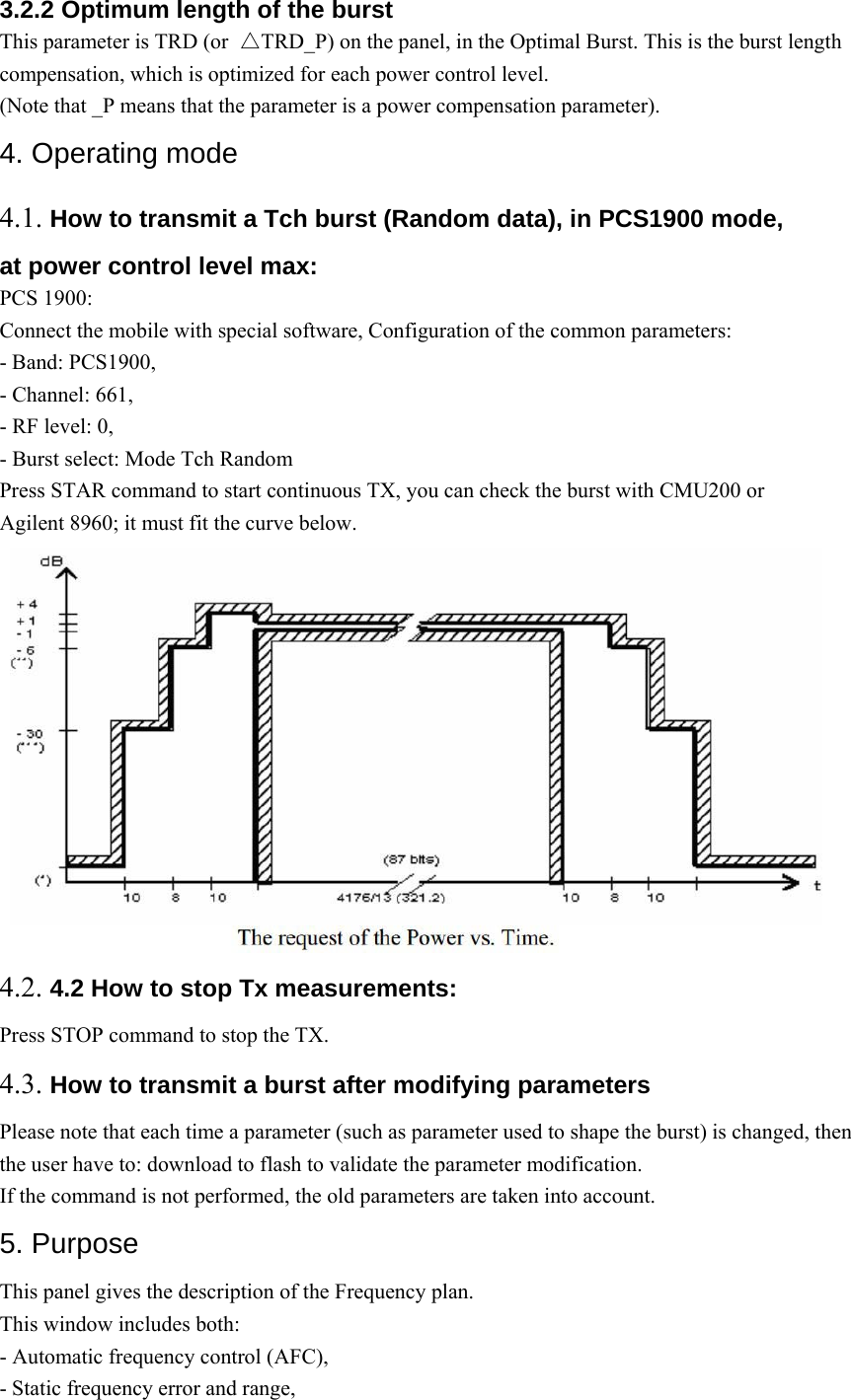
![TDMA format contains eight time slots. The handset power amplifier typically transmits in four of these up time slots. To prevent interference between cell phones, the time mask profile as specified is very restricted. To meet the GSM time mask, the output power of the PA needs to ramp up and down very quickly while staying within the time mask and not generating extraneous frequency bursts due to too abrupt ramp profiles. As described before, the Vramp input value sets the RF output power. By applying a certain ramp profile to the Vramp pin, the power level (Pout) of the PA is set to obtain the required time mask. A time mask of the PA’s output power is displayed. The time mask meets the limits (displayed by green lines) over a wide range of temperature, voltage and load variations. 3. Parameters F (n) are values coming from the DAC to shape the transmit burst. Some F(n) values have a corresponding Parameter used in the TAT to align the mobiles. Parameter used in TAT = [F (n)]. 3.1. Parameters used to shape the burst - H0 = [F (1)] controls the rate at which energy is given to the control loop at the beginning of the ramp. This energy is needed to bring the PA system control in a closed loop. This is the second code coming from the DAC. - PeakPow = [F (15)] corresponds to the peak power of the transmit burst. - H30 = [F (30)] corresponds to the last ramping coefficients used to shape the ramp. - MinPow = [F (31)] is a fixed parameter and corresponds to the Code Start of the AM7801 specification. It ensures a fast discharge of accumulated energy during the open loop mode in the summing node. 3.2. Parameters used to define the temporal position of the burst 3.2.1 Optimum position of the burst This parameter is TRU (or △TRU_P) on the panel, in the Optimal Burst. This is the burst starting time correction, which is optimised for each power control level. (Note that _P means that the parameter is a power compensation parameter).](https://usermanual.wiki/X-Wireless/V50LTE.User-Manual/User-Guide-3737354-Page-2.png)