XAC Automation E200NP Portable terminal User Manual Installation Guide xCL E200NP series 0117
XAC Automation Corporation Portable terminal Installation Guide xCL E200NP series 0117
User Manual
d
CLOUD POS PAYMENT DEVICE
XCL_E200NP SERIES
INSTALLATION GUIDE
xCL_E200NP series:
- xCL_E200NP-UN5
- xCL_E200NP-UNN
- xCL_E200NP-NN5
- xCL_E200NP-NNN
- xCL_E200NP-EN5
- xCL_E200NP-ENN
1.
P
ACKAGE
C
ONTENT
2.
D
EVICE
O
VERVIEW
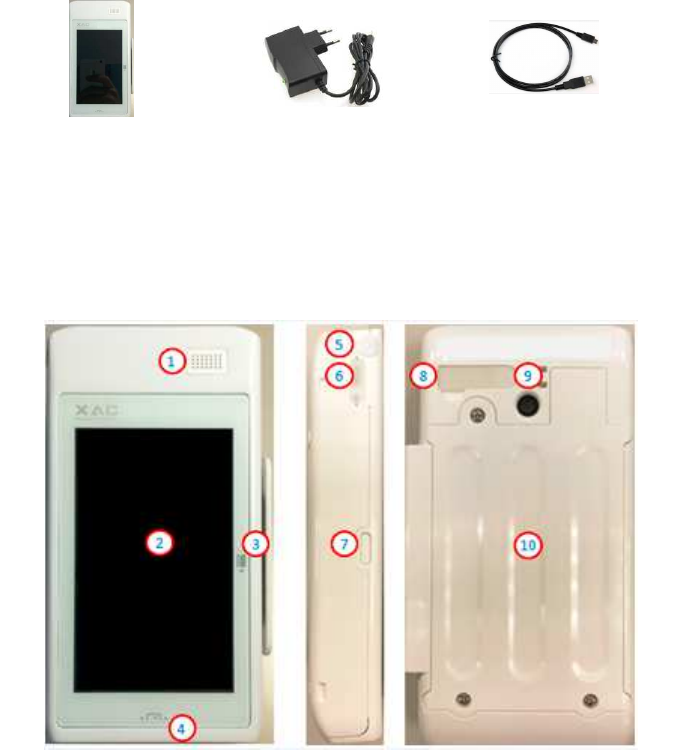
Take a view on your xCL_E200NP to find these Key Buttons & Interface Ports in Figure 1:
Figure 1
1. - Speaker
2. - Touch Display
3. - Magnetic Strip Reader slot
4. - Smart Card Reader slot
5. - Audio Jack
6. - Mini USB port
7. - Power Button
8. - Charging pins
9. - Camera
10. - Battery Compartment
Front Side (L) Bottom
xCL_E200NP Power adaptor USB cable
■ POS spec
Input: 5V DC, 2A
■
Power Adapter spec:
Input: 100~240 Vac
Output: 5V DC, 2A
This symbol is intended to alert the user before starting using the POS.
( Caution: Use only the AC adapter approved and provided by XAC Automation
Corporation for use with this device. Use of any other AC adapter may cause a risk of fire
or explosion)
Operating Temperature: 0
o
C to 40
o
C
2.
P
OWER
O
N
/O
FF THE
D
EVICE
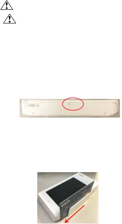
To power on the device, long press the Power key (Figure 2) for 5 seconds until a buzzer sound
is heard, and screen is activated.
To power off the device, press the Power key for 2 seconds to select Power Off on the menu to
shut down the device.
Figure 2
NOTE: xCL_E200NP will enter sleep mode automatically if unused for 1 minute.
3.
U
SING THE
M
AGNETIC
C
ARD
R
EADER
The magnetic card reader slot is on the right side of the device (Figure 3). Swipe the card
through the slot with magnetic stripe side facing the same direction as the display.
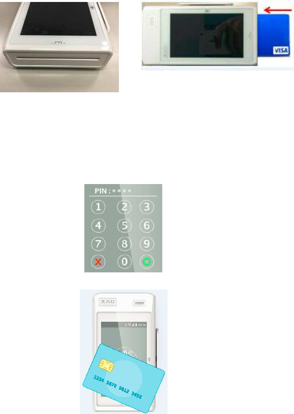
Figure 3
4.
U
SING THE
IC
C
ARD
R
EADER
The IC card reader slot is on the bottom of the device (Figure 4). Insert an IC card into the slot
with the chip side facing the same direction as the touch panel (Figure 5).
Figure 4 Figure 5
5.
U
SING THE VIRTUAL
K
EY
P
AD
After inserting the chip card, Press the numeric key as below Figure 6 to enter the desirable
numbers. Press Cancel(X) key to terminate any current function and press the Enter(O) key to
confirm a value or an option.
Figure 6
7.
U
SING THE
C
ONTACTLESS
C
ARD
R
EADER
Tap the contactless card on top of the contactless logo (Figure
7).
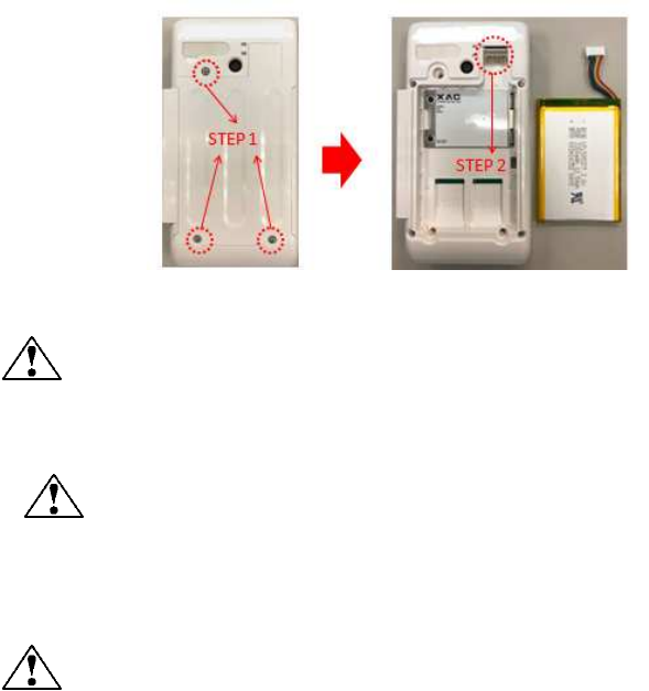
Figure 7
8.
R
EMOVE THE
B
ATTERY
STEP 1: Use the screw driver to remove 3 screws on the bottom cover as Figure 8.
STEP 2: After removing the bottom cover, pull up the battery connector as below Figure 9 to
change a new battery.
Figure 8 Figure 9
Bottom Cover Removal Warning
When removing the bottom cover and screws for the purposes of changing battery,
remember to put back the cover and screws before power on the POS.
CAUTION:
RISK OF EXPLOSION IF BATTERY IS REPLACED BY AN INCORRECT TYPE. DISPOSE OF USED BATTERIES
ACCORDING TO THE INSTRUCTIONS.
Warning for internal battery pack
To reduce risk of fire or burns:
1. Do not attempt to open, disassemble, or service the battery pack.
2.
Do not crush, puncture, short external contacts, or dispose of in fire or water.
3.
Do not heat above 60
o
C
8.
I
NSERT
SIM
&
SAM
CARD
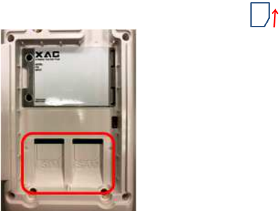
After removing the battery, the user can find SIM (left) & SAM (right) slots at the bottom side
of device. Please insert the card correctly as the icon shown on the cover:
Figure 10
FEDERAL COMMUNICATION COMMISSION INTERFERENCE STATEMENT
This device complies with Part 15 of the FCC Rules. Operation is subject to the following two conditions: (1)
This device may not cause harmful interference, and (2) this device must accept any interference received,
including interference that may cause undesired operation.
This equipment has been tested and found to comply with the limits for a Class A digital device, pursuant to
Part 15 of the FCC Rules. These limits are designed to provide reasonable protection against harmful
interference in a residential installation. This equipment generates, uses and can radiate radio frequency
energy and, if not installed and used in accordance with the instructions, may cause harmful interference to
radio communications. However, there is no guarantee that interference will not occur in a particular
installation. If this equipment does cause harmful interference to radio or television reception, which can
be determined by turning the equipment off and on, the user is encouraged to try to correct the interference
by one of the following measures:
- Reorient or relocate the receiving antenna.
- Increase the separation between the equipment and receiver.
- Connect the equipment into an outlet on a circuit different from that to which the receiver is connected.
- Consult the dealer or an experienced radio/TV technician for help.

FCC Caution: Any changes or modifications not expressly approved by the party responsible for compliance
could void the user's authority to operate this equipment.
This transmitter must not be co-located or operating in conjunction with any other antenna or transmitter.
Operations in the 5.15-5.25GHz band are restricted to indoor usage only
Radiation Exposure Statement:
The product comply with the FCC portable RF exposure limit set forth for an uncontrolled environment and
are safe for intended operation as described in this manual. The further RF exposure reduction can be
achieved if the product can be kept as far as possible from the user body or set the device to lower output
power if such function is available.
The above information is the exclusive intellectual property of XAC Automation Corporation and shall not be
disclosed, distributed or reproduced without permission of XAC Automation Corporation.
XAC Automation Corporation
886
-
3
-
577
-
2738