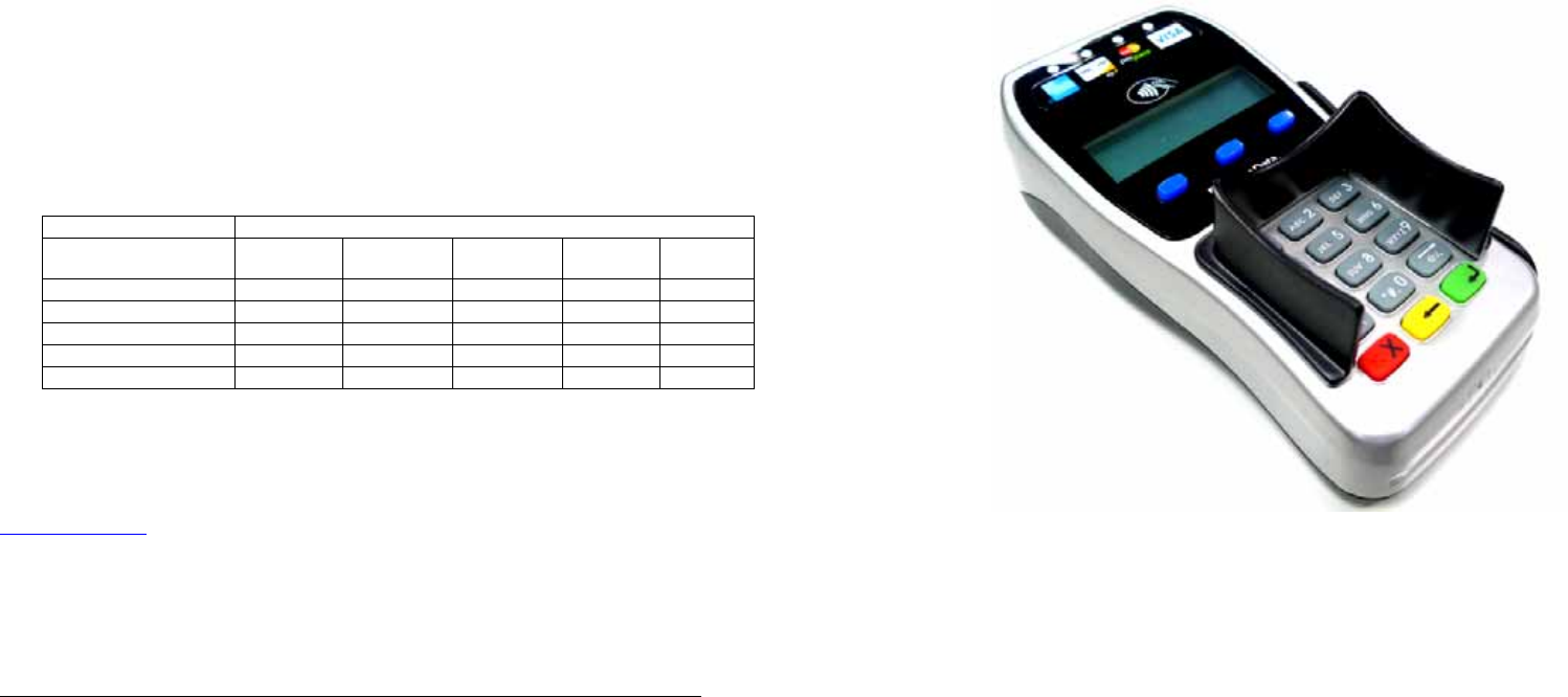
XAC Automation FD35 Handheld PINpad User Manual
XAC Automation Corporation Handheld PINpad
User Manual
This device complies with Part 15 of the FCC Rules. Operation is subject to the following two conditions: (1)
This device may not cause harmful interference, and (2) this device must accept any interference received,
including interference that may cause undesired operation.
Warning: If the device, FD-35, FD-35-ZKA is used without the detachable privacy shield, the
following criteria needs to be met by the Installed Environment of the PED for complying with
the PCI privacy screen design requirement:
A. Positioning of the PED on the check-stand in such way as to make visual observation of the
PIN-entry process infeasible.
Visual shields designed into the check-stand.
Position the PED so that it is angled in such a way to make PIN spying difficult.
B. Pop-up (temporary) privacy shield attached to the PED mounting stand. Consumer (through
education & prompting) or merchant would put the shield in place during PIN entry.
C. Installing PED on an adjustable stand that allows consumers to swivel the terminal sideways
and/or tilt it forwards/backwards to a position that makes visual observation of the PIN-
entry process difficult.
D. Positioning of in-store security cameras such that the PIN-entry keypad is not visible.
Instructing the cardholder regarding safe PIN-entry, done with a combination of:
Signage on the PED.
Prompts on the display, possibly with a "click-through" screen.
Potentially literature at the point of sale.
A logo for safe PIN-entry process.
Table A1: Matrix of Observation Corridors and PIN Protection Method
Observation Corridors
Method Cashier
Customers
in Queue Customers
Elsewhere On-Site
Cameras Remote
Cameras
PED Stand A M H L L L
PED Stand B H H H L M
Check-Stand A L M M L H
Check-Stand B H H M H H
Customer Instruction H* H* H* H* H*
z Customer Instruction methods are less repeatable and therefore should be used in combination
with other methods. L = low, M = medium, H = high.
XAC Automation Corporation
886-3-577-2738
www.xac.com.tw
The above information is the exclusive intellectual property of XAC Automation Corporation
and shall not be disclosed, distributed or reproduced without permission of XAC Automation
Corporation.
XAC AUTOMATION CORP. shall not be held liable for technical and editorial omissions or
errors made herein; nor for incidental or consequential damages resulting from the furnishing,
performance or use of his material.
This document contains proprietary information protected by copyright. All rights are reserve.
FD-35, FD-35-ZKA
PIN PAD
INSTALLATION GUIDE
1. CONNECTING THE FD35 PIN PAD
The FD-35, FD-35-ZKA device can be used to connect with PC/
terminal. It supports RJ12 offset, USB interfaces via different
cable types such as RJ12 offset and standard USB via mini din
(Figure 1) type connector.
Note: Turn off or unplug the terminal/PC whenever you
connect or disconnect the PIN Pad. Be sure the terminal/PC
is not processing data when powering down.
Plug the USB connector of FD-35, FD-35-ZKA to the USB port
at the top end of a PC.
PIN pad Input voltage: 5Vdc / 500mA (USB)
Operating Temperature: 0ºC ~ 40 ºC
RTC battery: 3V, CR2032
Caution: Risk of explosion if the battery is replaced by an
incorrect type. Please dispose of used battery according to the
instructions.
Caution:
• It shall not be removable from other parts of the FIRE
ENCLOSURE by the OPERATOR (Figure 2); and
• It shall be provided with a means to keep it closed during
normal operation (Figure 3).
2. MAGNETIC STRIPE READER
Find the card reader slot at the right side of PIN Pad.
Slide the card in either direction through the slot without
stopping. If the card swipe fails, check the position of the
magnetic stripe and slide the card again. (Figure 4)
3. USING THE CARD READER
Find the card reader slot on bottom of PIN Pad. Please insert
the card completely and make sure that it cannot be moved
forward anymore. If inserted failed, check the position of the
card and insert the card again. (Figure 5)
4. USING THE PINPAD
Press numeral key to enter password if needed. Then press green
[ENTER] key to finish password key-in. Press red [CANCEL] key
to exit from presently status (Figure 6). If the PIN is entered
incorrectly, press yellow key and reenter it.
Figure 1
Figure 2
Figure 3
Figure 4
Figure 5
Figure 6
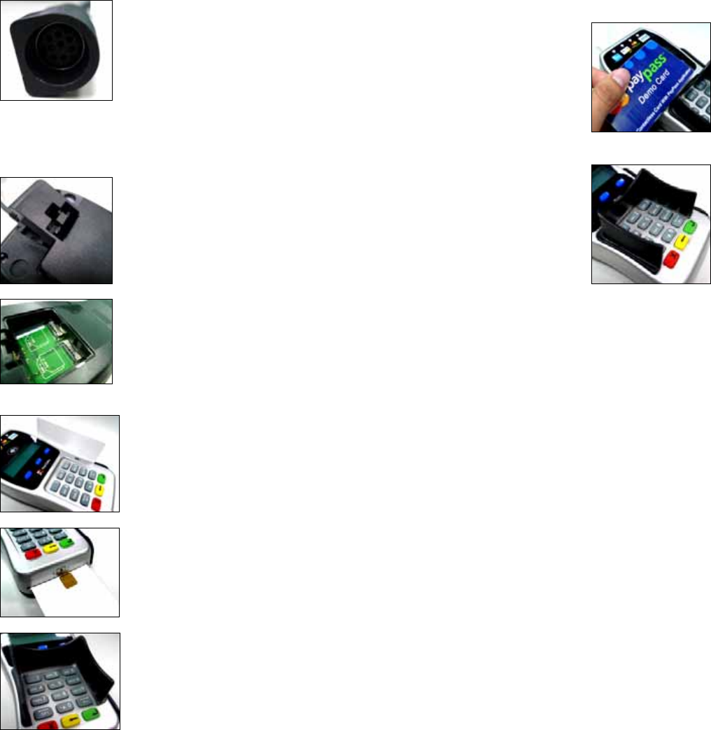
5. CONTACTLESS READER
Contactless reader is on the top of FD-35, FD-35-ZKA. It will light
up with blue color signal when FD-35, FD-35-ZKA is powered on
and that means reader is
working normally.
Put contactless card to approach the signal icon in the middle
area of card reader (Figure 7) for reading the card data during
transaction.
6. INSTALLING THE PRIVACY SHIELD
The privacy shield is installed on the device, and the keypad will
be separated from the LCD. (Figure 8)
7. CLEANING
Periodically clean the PIN Pad device with a clean cloth
dampened with water and a mild soap or cleaner. Do not use
harsh chemicals.
8. RETURNING THE PIN PAD DEVICE
If you need to return your PIN Pad device for service or
replacement, contact your service provider or sales representative
for instructions.
Note: Do not try to service, repair or adjust the PIN Pad device in
any other way; doing so will void your warranty.
You are cautioned that changes or modifications not expressly
approved by the party responsible for compliance could void your
authority to operate the equipment.
Federal Communication Commission Interference Statement
This equipment has been tested and found to comply with the limits for a Class
B digital device, pursuant to Part 15 of the FCC Rules. These limits are
designed to provide reasonable protection against harmful interference in a
residential installation. This equipment generates, uses and can radiate radio
frequency energy and, if not installed and used in accordance with the
instructions, may cause harmful interference to radio communications.
However, there is no guarantee that interference will not occur in a particular
installation. If this equipment does cause harmful interference to radio or
television reception, which can be determined by turning the equipment off and
on, the user is encouraged to try to correct the interference by one of the
following measures:
- Reorient or relocate the receiving antenna.
- Increase the separation between the equipment and receiver.
- Connect the equipment into an outlet on a circuit different from that to
which the receiver is connected.
- Consult the dealer or an experienced radio/TV technician for help.
FCC Caution: Any changes or modifications not expressly approved by the
party responsible for compliance could void the user's authority to operate this
equipment.
Figure 7
Figure 8