XAC Automation FD400GTMC Portable Terminal User Manual
XAC Automation Corporation Portable Terminal
UserManual.wiki
>
XAC Automation
>
FD400GTMC User Manual
User Manual
Navigation menu
Upload a User Manual
Namespaces
Wiki Guide
HTML
PDF
Info
Views
User Manual
Discussion / Help
Navigation
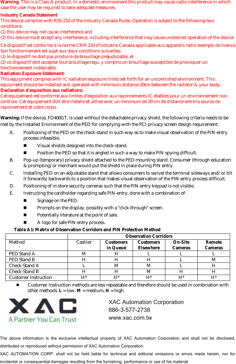
![4. USING THE MAGNETIC CARD READER Find the reader slot in the middle of surface. Swipe card through slot from left to right or the opposite direction with stripe lies down and facing the display (Figure 7). Figure 75. USING THE CONTACTLESS CARD READER Contactless reader antenna is around the display and PIN pad. It will light up with blue color signal when FD400GT is powered on and that means reader is working normally. Put contactless card to approach the antenna of card reader (Figure 8) for reading the card data during transaction. Figure 86. USING THE KEY PAD To enter numbers or letters, simply press the appropriate key. For example, to type the letter A: Press [ALPHA], then [A] (the Void key) (Figure 9). Figure 9Caution: For body worn operation, this terminal will keep away 20cm from the body in order to meet the FCC RF exposure guidelines Caution: Use only shielded signal cables to connect I/O devices to this equipment. You are cautioned that changes or modifications not expressly approved by the party responsible for compliance could void your authority to operate the equipment. This device complies with Part 15 of the FCC Rules. Operation is subject to the following two conditions: (1) This device may not cause harmful interference, and (2) this device must accept any interference received, including interference that may cause undesired operation. Federal Communication Commission Interference Statement This equipment has been tested and found to comply with the limits for a Class A digital device, pursuant to Part 15 of the FCC Rules. These limits are designed to provide reasonable protection against harmful interference in a residential installation. This equipment generates, uses and can radiate radio frequency energy and, if not installed and used in accordance with the instructions, may cause harmful interference to radio communications. However, there is no guarantee that interference will not occur in a particular installation. If this equipment does cause harmful interference to radio or television reception, which can be determined by turning the equipment off and on, the user is encouraged to try to correct the interference by one of the following measures: - Reorient or relocate the receiving antenna. - Increase the separation between the equipment and receiver. - Connect the equipment into an outlet on a circuit different from that to which the receiver is connected. - Consult the dealer or an experienced radio/TV technician for help. FCC Caution: Any changes or modifications not expressly approved by the party responsible for compliance could void the user's authority to operate this equipment. IMPORTANT NOTE: FCC Radiation Exposure Statement: This equipment complies with FCC radiation exposure limits set forth for an uncontrolled environment. This equipment should be installed and operated with minimum distance 20cm between the radiator & your body. This transmitter must not be co-located or operating in conjunction with any other antenna or transmitter.](https://usermanual.wiki/XAC-Automation/FD400GTMC/User-Guide-1879349-Page-3.png)