XAC Automation T100SE Terminal User Manual
XAC Automation Corporation Terminal
User Manual

Radiation Exposure Statement:
This equipment complies with FCC radiation exposure limits set forth for an uncontrolled environment. This
equipment should be installed and operated with minimum distance 20cm between the radiator & your body.
FCC REQUIREMENTS
This equipment complies with Part 68 of the FCC rules and the requirements adopted by the ACTA. On the bottom
of this equipment is a label that contains, among other information, a product identifier in the format US:
N7KMM09BT100SEIf requested, this number must be provided to the telephone company.
Applicable connector jack Universal Service Order Codes (“USOC”) for the Equipment is RJ11C.
A plug and jack used to connect this equipment to the premises wiring and telephone network must comply with
the applicable FCC Part 68 rules and requirements adopted by the ACTA. A compliant telephone cord and modular
plug is provided with this product. It is designed to be connected to a compatible modular jack that is also
compliant. See installation instructions for details.
The REN is used to determine the number of devices that may be connected to a telephone line. Excessive RENs
on a telephone line may result in the devices not ringing in response to an incoming call. In most but not all areas,
the sum of RENs should not exceed five (5.0). To be certain of the number of devices that may be connected to a
line, as determined by the total RENs, contact the local telephone company. For products approved after July 23,
2001, the REN for this product is part of the product identifier that has the format US: N7KMM09BT100SE
The digits represented by 09B are the REN without a decimal point (e.g., 03 is a REN of 0.3). For earlier products,
the REN is separately shown on the label.
If your equipment causes harm to the telephone network, the telephone company will notify you in advance that
temporary discontinuance of service may be required. But if advance notice isn't practical, the telephone company
will notify the customer as soon as possible. Also, you will be advised of your right to file a complaint with the FCC
if you believe it is necessary. The telephone company may make changes in its facilities, equipment, operations or
procedures that could affect the operation of the equipment. If this happens the telephone company will provide
advance notice in order for you to make necessary modifications to maintain uninterrupted service.
If trouble is experienced with this equipment, for repair or warranty information, please contact
COMPANY: Zakus, INC.
ADDRESS: 146 Main Street, suite 208 Los Altos, CA 94022 U.S.A.
TEL NO: +1-650-917-9158
If the equipment is causing harm to the telephone network, the telephone company may request that you
disconnect the equipment until the problem is resolved. Connection to party line service is subject to state tariffs.
Contact the state public utility commission, public service commission or corporation commission for information.
If your home has specially wired alarm equipment connected to the telephone line, ensure the installation of this
equipment does not disable your alarm equipment. If you have questions about what will disable alarm
equipment, consult your telephone company or a qualified installer.
WHEN PROGRAMMING EMERGENCY NUMBERS AND (OR) MAKING TEST CALLS TO EMERGENCY
NUMBERS:
1) Remain on the line and briefly explain to the dispatcher the reason for the call.
2) Perform such activities in the off-peak hours, such as early morning or late evenings.
Federal Communication Commission Interference Statement
This device complies with Part 15 of the FCC Rules. Operation is subject to the following two conditions: (1) This
device may not cause harmful interference, and (2) this device must accept any interference received, including
interference that may cause undesired operation.
This equipment has been tested and found to comply with the limits for a Class B digital device, pursuant to Part
15 of the FCC Rules. These limits are designed to provide reasonable protection against harmful interference in a
residential installation. This equipment generates, uses and can radiate radio frequency energy and, if not installed
and used in accordance with the instructions, may cause harmful interference to radio communications. However,
there is no guarantee that interference will not occur in a particular installation. If this equipment does cause
harmful interference to radio or television reception, which can be determined by turning the equipment off and on,
the user is encouraged to try to correct the interference by one of the following measures:
- Reorient or relocate the receiving antenna.
- Increase the separation between the equipment and receiver.
- Connect the equipment into an outlet on a circuit different from that to which the receiver is connected.
- Consult the dealer or an experienced radio/TV technician for help.
FCC Caution: Any changes or modifications not expressly approved by the party responsible for compliance could
void the user's authority to operate this equipment.
This transmitter must not be co-located or operating in conjunction with any other antenna or transmitter.
Caution
To reduce the risk of fire, use only No. 26 AWG or larger UL Listed or CSA Certified Telecommunication Line Cord.
XAC TRANSACTION TERMINAL
T100-SE
INSTALLATION GUIDE
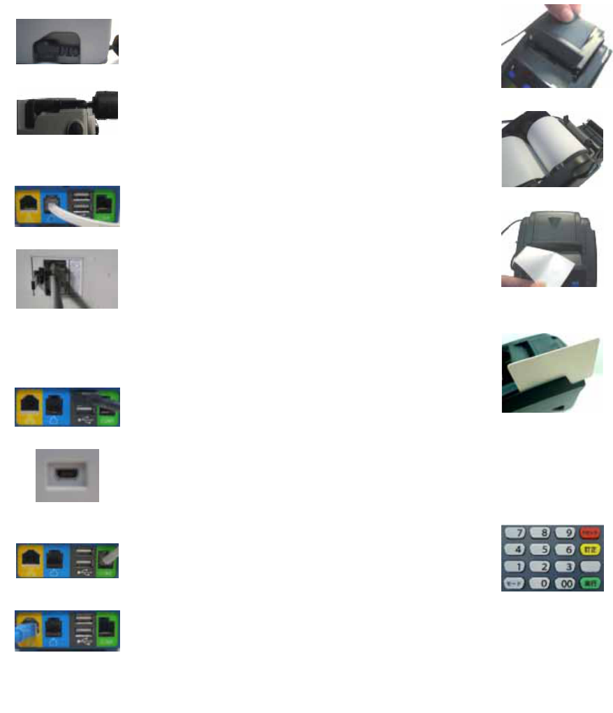
2. LOADING THE PAPER
Gently pop the printer cover’s latch to open the
cover (Figure 9); then lift the cover.
Load a roll of thermal paper (Appleton 1012
recommended) into the printer (Figure 10). Load it
so that the print-side of the paper will feed out
facing the operator.
Close the cover by pressing down evenly on both
side tabs, or by pressing on the center of the printer
cover.
Use the serrated bar to tear off any excess paper
(Figure 11). The printer is now ready to use.
3. USING THE CARD READER
With the idle message displayed, select the desired
transaction type. Insert the card into the card reader
slot, with the magnetic stripe facing down and to the
left of the terminal (Figures 12).
For magnetic card, slide the card in either direction
through the slot without stopping. If the card swipe
fails, check the position of the magnetic stripe and
slide the card again.
Follow remaining prompts on the display to
complete the transaction. See your quick reference
guide or user’s manual for details.
4. USING THE KEY PAD
The keypad allows you to select transaction types
and enter information. Its 16 keys can be used to
select numbers, letters, and to enter data (Figure
13).
Figure 9
Figure 10
Figure 11
Figure 12
Figure 13
1. INSTALLING THE CABLES
Find the power input on the right side of the terminal.
Connect the plug from the power adapter into the power
input (Figure 1). Thread the cord through its designated
channel (Figure 2). Plug the power adapter into a 120-volt
electrical outlet or into a surge suppressor (recommended)
after the power cord is connected to the power adapter.
Adapter spec. :
LI SHIN INT. / LSE0107A1240
Input: 100-240Vac, 50/60Hz 1A
Output: 12Vdc, 3.33A
Operating Temperature: 0 oC to 40 oC
Modem Speed: V.22bis 2400bps/ V.32bis 14400bps
RTC battery spec. : 3V, CR2032.
Connect one end of the phone cord into one of the jacks
on the back of the terminal (Figure 3). Plug the other end
of the cord into a modular wall jack (Figure 4). Use only a
jack for an analog line like a fax line or a standard
telephone.
Caution: Risk of explosion if the battery is replaced by an
incorrect type. Please dispose of used battery according to
the instructions.
(Optional) This terminal supports three USB ports. Two
USB host ports locate on the back of the terminal (Figure
5). One USB device port locates on the left side of the
terminal (Figure 6). If the terminal uses a peripheral device
with USB connector, plug it into the USB host port.
(Optional) This terminal supports one RS-232 ports of
RJ-12 offset keyed connector. If the terminal uses a
peripheral device with this type of connector and interface,
plug it into the RS-232 port on the back of the terminal
(Figure 7).
(Optional) If the terminal needs communication over
Ethernet, plug cable into the RJ-45 port on the back of the
terminal (Figure 8).
Figure 1
Figure 2
Figure 3
Figure 4
Figure 5
Figure 6
Figure 7
Figure 8

WiFi specification information
Data Rate 802.11b: 11 / 5.5 / 2 / 1Mbps
802.11g: 54 / 48 / 36 / 24 / 18 / 12 / 9 / 6Mbps
Draft 802.11n (20MHz, 800ns GI): 65 / 58.5 / 52 / 39 / 26 / 19.5 / 13 / 6.5Mbps
Draft 802.11n (40MHz, 800ns GI): 135 / 121.5 / 108 / 81 / 54 / 40.5 / 27 /
13.5Mbps
Draft 802.11n (20MHz, 400ns GI): 72.2 / 65 / 57.8 / 43.3 / 28.9 / 21.7 / 14.4 /
7.2Mbps
Draft 802.11n (40MHz, 400ns GI): 150 / 135 / 120 / 90 / 60 / 45 / 30 / 15Mbps
Type of
Modulation CCK, DQPSK, DBPSK for DSSS
64QAM, 16QAM, QPSK, BPSK for OFDM
Frequency
Range 2412MHz ~ 2462MHz
Number of
Channel For 802.11b, 802.11g, draft 802.11n (20MHz) :
FCC: 11
For draft 802.11n (40MHz) :
FCC countries: 7