XAC Automation T103LE Terminal User Manual rev 2
XAC Automation Corporation Terminal rev 2
User Manual rev 2.pdf

ALL IN ONE PAYMENT TERMINAL
INSTALLATION GUIDE
MODEL:
xAPT-103LE
xCE_T103LE
1. BEFORE STARTING
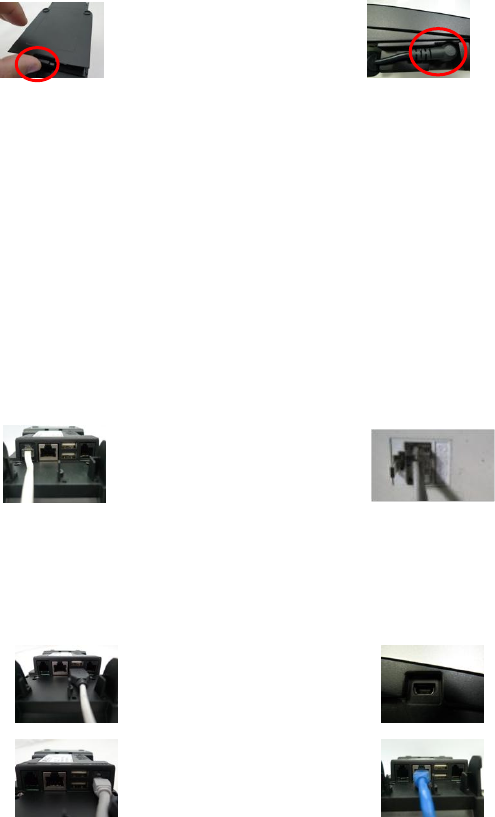
Open the gate behind the device (Figure 1), and find the power input on the right side of the terminal. Connect the
plug from the power adapter into the power input (Figure 2). Plug the power adapter into a 120-volt electrical outlet
or into a surge suppressor (recommended) after the power cord is connected to the power adapter.
Figure 1 Figure 2
Operating Temperature: 0 C to 40 C
Modem Speed: V.22bis 2400bps/ V.32bis 14400bps
RTC battery spec. : 3V, CR2032
Adapter: HON-KWANG, HK-AX-120A200 -WW (WW = EU, US represent the different plug types), I/P:
100-240Vac, 50-60Hz, 0.8A, O/P: 12Vdc, 2.0A
Adapter (Alternate): Delta Electronics Inc, ADP-36PH B, I/P: 100-240Vac,50-60Hz, 1A,O/P: 12Vdc,3.0A, LPS.
* Power Adapter: DC 12V, 2A or 3A(Output Rating)
(Use only the XAC Automation Corporation provided AC adapter approved for use with this device. Use
of another AC adapter may cause a fire or explosion)
Caution: The cover (Figure 5) shall be provided with a means to keep it closed during normal operation.
Caution: Risk of explosion if the battery is replaced by an incorrect type. Please dispose of used battery according to the instructions.
Warning: A shielded-type power cord is required in order to meet FCC emission limits and also to prevent interference to the nearby
radio and television reception. It is essential that only the supplied power cord be used.
Connect one end of the phone cord into one of the jacks on the back of the terminal (Figure 3). Plug the other end of
the cord into a modular wall jack (Figure 4). Use only a jack for an analog line like a fax line or a standard telephone.
Figure 3 Figure 4
(Optional) This terminal supports three USB ports. Two USB host ports locate on the back of the terminal (Figure 5). One USB device
port locates on the left side of the terminal (Figure 6). If the terminal uses a peripheral device with USB connector, plug it into the USB
host port.
(Optional) This terminal supports one RS-232 ports of RJ-12 offset keyed connector. If the terminal uses a peripheral device with this
type of connector and interface, plug it into the RS-232 port on the back of the terminal (Figure 7).
(Optional) If the terminal needs communication over Ethernet, plug cable into the RJ-45 port on the back of the terminal (Figure 8).
Figure 5 Figure 6
Figure 7 Figure 8
2. POWER ON THE TERMINAL
Plug the power cord into the power jack and plug the power adapter into a 120-volt electrical outlet or into a surge
suppressor (recommended) after the power cord is connected to the power adapter. T103LE would start to boot
automatically.
3. LOADING THE PAPER
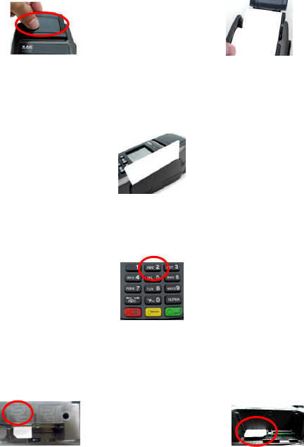
Gently pop the printer cover’s latch to open the cover (Figure 9); then lift the cover. Load a roll of thermal paper
(Appleton 1012 recommended) into the printer (Figure10). Load it so that the print-side of the paper will feed out
facing the operator. Close the cover by pressing down evenly on both side tabs, or by pressing on the center of the
printer cover. Use the serrated bar to tear off any excess paper.
Figure 9 Figure 10
4. USING THE MAGNETIC CARD READER
Magnetic Card Reader
Find the card reader slot at the right side of terminal. Slide the card in either direction through the slot without
stopping. If the card swipe fails, check the position of the magnetic stripe and slide the card again (Figure 11).
Figure 11
5. USING THE KEY PAD
To enter numbers or letters, simply press the appropriate key. For example, to type the letter B: Press and release [B]
twice times, then display shows B (Figure 12).
Figure 12
6. INSTALLING THE SAM CARD
There are four SAM slots located on the left side of the device (Figure 13). Before insert the SAM card, please turn off
the device. Insert the SAM card in the slot in figure 16. Make sure SAM cards inserted in the right direction (Figure
14).
Figure 13 Figure 14
Caution: When removing bottom cover for the purposes of cable or SAM card installation, remember to reinstallation the protective cover and make sure to keep it in place.
Caution: To reduce the risk of fire, use only No. 26 AWG or larger UL Listed or CSA Certified Telecommunication Line Cord.
Caution: Risk of explosion if the battery is replaced by an incorrect type. Please dispose of used battery according to the instructions.
Warning: This is a Class A product. In a domestic environment this product may cause radio interference in which case the user may be required to take adequate measures.
Warning: If the device, T103, is used without the detachable privacy shield, the following criteria needs to be met by the Installed Environment of the PED for complying with the PCI privacy screen design requirement:
A. Positioning of the PED on the check-stand in such way as to make visual observation of the PIN-entry process infeasible.
Visual shields designed into the check-stand.
Position the PED so that it is angled in such a way to make PIN spying difficult.
B. Pop-up (temporary) privacy shield attached to the PED mounting stand. Consumer (through education & prompting) or merchant would put the shield in place during PIN entry.
C. Installing PED on an adjustable stand that allows consumers to swivel the terminal sideways and/or tilt it forwards/backwards to a position that makes visual observation of the PIN-entry process difficult.
D. Positioning of in-store security cameras such that the PIN-entry keypad is not visible.
E. Instructing the cardholder regarding safe PIN-entry, done with a combination of:
Signage on the PED.
Prompts on the display, possibly with a "click-through" screen.
Potentially literature at the point of sale.
A logo for safe PIN-entry process.
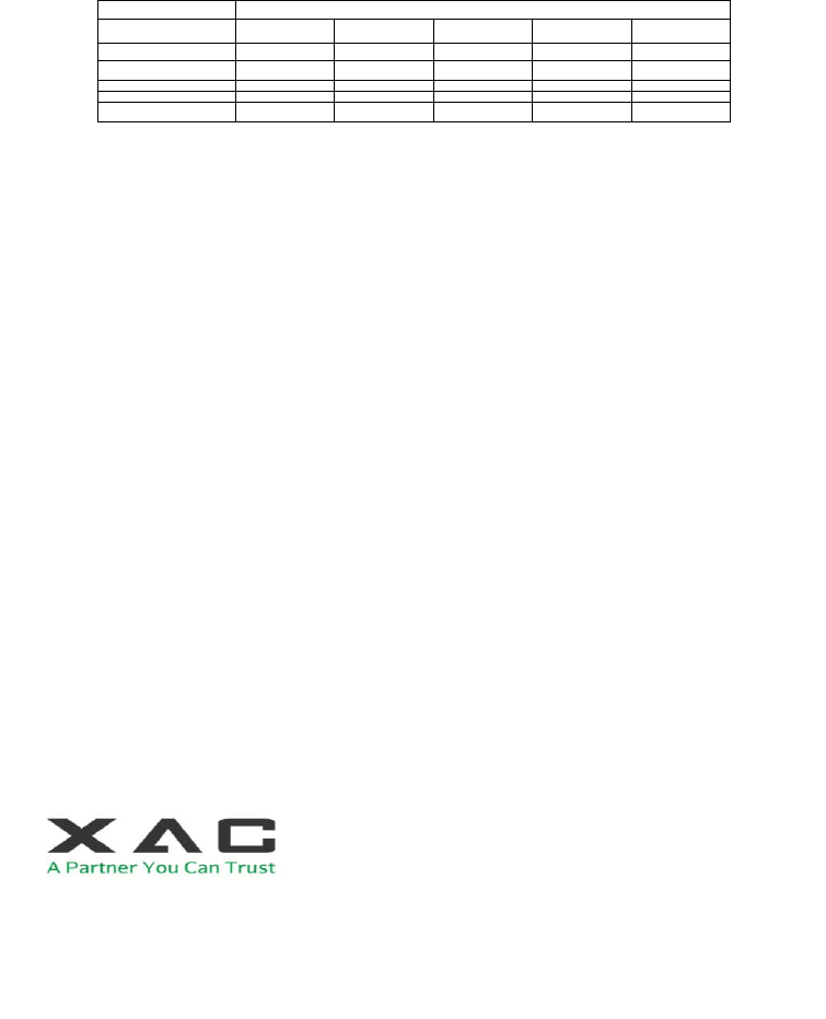
Table A1: Matrix of Observation Corridors and PIN Protection Method
Observation Corridors
Method
Cashier
Customers
in Queue
Customers
Elsewhere
On-Site
Cameras
Remote
Cameras
PED Stand A
M
H
L
L
L
PED Stand B
H
H
H
L
M
Check-Stand A
L
M
M
L
H
Check-Stand B
H
H
M
H
H
Customer Instruction
H*
H*
H*
H*
H*
Customer Instruction methods are less repeatable and therefore should be used in combination with other methods. L = low, M = medium, H = high.
Industry Canada Statement
NOTICE: This equipment meets the applicable Industry Canada Terminal Equipment Technical Specifications. This is confirmed by the registration number. The abbreviation, IC, before the registration number signifies that registration was
performed based on a Declaration of Conformity indicating that Industry Canada technical specifications were met. It does not imply that Industry Canada approved the equipment.
NOTICE: The Ringer Equivalence Number (REN) for this terminal equipment is 0.1. The REN assigned to each terminal equipment provides an indication of the maximum number of terminals allowed to be connected to a telephone interface.
The termination on an interface may consist of any combination of devices subje
ct only to the requirement that the sum of the Ringer Equivalence Numbers of all the devices does not exceed five.
AVIS : Le présent matériel est conforme aux spécifications techniques d’Industrie Canadaapplicables au matériel terminal. Cette conformité est confirmée par le numérod'enregistrement. Le sigle IC, placé devant le numéro d'enregistrement,
signifie quel’enregistrement s’est effectué conformément à une déclaration de conformité et indique queles spécifications techniques d'Industrie Canada ont été respectées. Il n’implique pasqu’Industrie Canada a approuvé le matériel.
AVIS : L'indice d'équivalence de la sonnerie (IES) du présent matériel est de 0.1. L'IESassigné à chaque dispositif terminal indique le nombre maximal de terminaux qui peuvent êtreraccordés à une interface téléphonique. La terminaison d'une
interface peut consister en unecombinaison quelconque de dispositifs, à la seule condition que la somme d'indicesd'équivalenc e de la sonnerie de tous les dispositifs n'excède pas 5.
This device complies with RSS-247 of the Industry Canada Rules. Operation is subject to the following two conditions:
(1) This device may not cause harmful interference, and
(2) this device must accept any interference received, including interference that may cause undesired operation.
Ce dispositif est conforme à la norme CNR-247 d'Industrie Canada applicable aux appareils radio exempts de licence. Son fonctionnement est sujet aux deux conditions suivantes:
(1) le dispositif ne doit pas produire de brouillage préjudiciable, et
(2) ce dispositif doit accepter tout brouillage reçu, y compris un brouillage susceptible de provoquer un fonctionnement indésirable.
Radiation Exposure Statement:
The product comply with the Canada portable RF exposure limit set forth for an uncontrolled environment and are safe for intended operation as described in this manual. The further RF exposure reduction can be achieved if the product can be kept as far as possible
from the user body or set the device to lower output power if such function is available.
Declaration d'exposition aux radiations:
Le produit est conforme aux limites d'exposition pour les appareils portables RF pour les Etats-Unis et le Canada établies pour un environnement non contrôlé.
Le produit est sûr pour un fonctionnement tel que décrit dans ce manuel. La réduction aux expositions RF peut être augmentée si l'appareil peut être conservé aussi loin que possible du corps de l'utilisateur ou que le dispositif est réglé sur la puissance de sortie la plus
faible si une telle fonction est disponible.
Federal Communication Commission Interference Statement
This device complies with Part 15 of the FCC Rules. Operation is subject to the following two conditions: (1) This device may not cause harmful interference, and (2) this device must accept any interference received, including interference that
may cause undesired operation.
This equipment has been tested and found to comply with the limits for a Class A digital device, pursuant to part 15 of the FCC Rules. These limits are designed to pro-vide reasonable protection against harmful interference when the
equipment is operate din a commercial environment. This equipment generates, uses, and can radiate radiofrequency energy and, if not installed and used in accordance with the instruction manual, may cause harmful interference to radio
communications. Operation of this equipment in a residential area is likely to cause harmful interference in which case the user will be required to correct the interference at his own expense.
FCC Caution: Any changes or modifications not expressly approved by the party responsible for compliance could void the user's authority to operate this equipment.
Caution: Use only shielded signal cables to connect I/O devices to this equipment. You are cautioned that changes or modifications not expressly approved by the party responsible for compliance could void your authority to operate the
equipment.
IMPORTANT NOTE:
FCC Radiation Exposure Statement:
The product comply with the FCC portable RF exposure limit set forth for an uncontrolled environment and are safe for intended operation as described in this manual. The further RF exposure reduction can be achieved if the product can be kept as far as possible
from the user body or set the device to lower output power if such function is available.
Warning: This is a Class A product. In a domestic environment this product may cause radio interference in which case the user may be required to take adequate measures.
FCC REQUIREMENTS
This equipment complies with Part 68 of FCC Rules. On the base unit of this equipment is a label that contains, among other information, the FCC Registration Number and Ringer Equivalence Number (REN) for this equipment. IF
REQUESTED, THIS INFORMATION MUST BE GIVEN TO THE TELEPHONE COMPANY.
This equipment complies with Part 68 of the FCC rules and the requirements adopted by the ACTA. On the bottom of this equipment is a label that contains, among other information, a product identifier in the format US: N7KMM01BT103LE.
If requested, this number must be provided to the telephone company. The REN is used to determine the number of devices that may be connected to a telephone line. Excessive RENs on a telephone line may result in the devices not ringing in
response to an incoming call. In most but not all areas, the sum of RENs should not exceed five (5.0). To be certain of the number of devices that may be connected to a line, as determined by the total RENs, contact the local telephone company.
For products approved after July 23, 2001, the REN for this product is part of the product identifier that has the format N7KMM01BT103LE. The digits represented by 01B are the REN without a decimal point (e.g., 03 is a REN of 0.3). For earlier
products, the REN is separately shown on the label. If your equipment causes harm to the telephone network, the telephone company may discontinue your service temporarily. If possible, they will notify you in advance. But if advance notice
is not practical, you will be notified as soon as possible. You will be informed of your right to file a complaint with the FCC. Your telephone company may make changes in its facilities, equipment, operations or procedures that could affect the
proper functioning of your equipment. If they do, you will be notified in advance to give you an opportunity to maintain uninterrupted telephone service. If you experience trouble with this telephone equipment, please contact the following
address and phone number for information on obtaining service or repairs. The telephone company may ask that you disconnect this equipment from the network until the problem has been corrected or until you are sure that the equipment is
not malfunctioning. This equipment may not be used on coin service provided by the telephone company. Connection to party lines is subject to sta te tariffs.
COMPANY: Zakus, INC.
ADDRESS: 146 Main Street, suite 208 Los Altos, CA 94022 U.S.A.
TEL NO: 650-917-9158
A plug and jack used to connect this equipment to the premises wiring and telephone network must comply with the applicable FCC Part 68 rules and requirements adopted by the ACTA. A compliant telephone cord and modular plug is
provided with this product. It is designed to be connected to a compatible modular jack that is also compliant. See installat ion instructions for details.
The above information is the exclusive intellectual property of XAC Automation Corporation and shall not be disclosed,
distributed or reproduced without permission of XAC Automation Corporation.
XAC AUTOMATION CORP. shall not be held liable for technical and editorial omissions or errors made herein; nor for
incidental or consequential damages resulting from the furnishing, performance or use of his material.
XAC Automation Corporation
886-3-577-2738
www.xac.com.tw