XAC Automation T103WIFI3GT Terminal User Manual
XAC Automation Corporation Terminal
User Manual rev 2.pdf

ALL IN ONE PAYMENT TERMINAL
INSTALLATION GUIDE
MODEL:
xAPT-103WiFi.3G
xCE_T103WiFi.3G
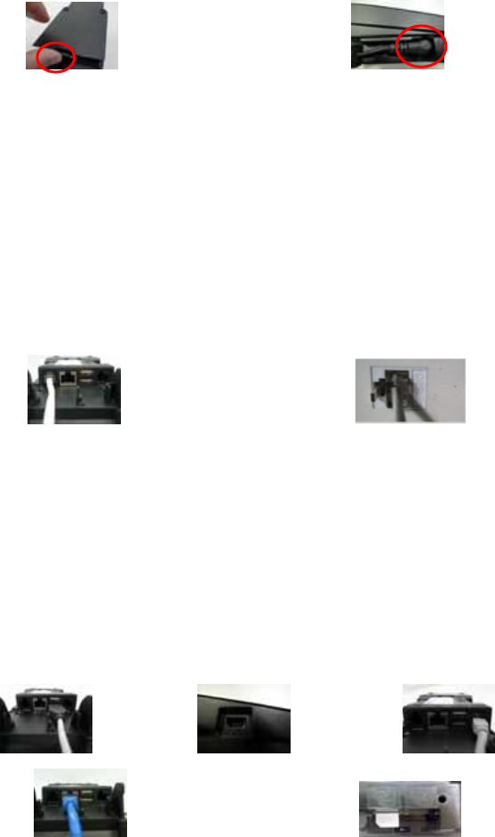
1. BEFORE STARTING
Open the gate behind the device (Figure 1), and find the power input on the right side of the terminal. Connect
the plug from the power adapter into the power input (Figure 2). Plug the power adapter into a 120-volt
electrical outlet or into a surge suppressor (recommended) after the power cord is connected to the power
adapter.
Figure 1 Figure 2
Operating Temperature: 0 °C to 40 °C
Modem Speed: V.22bis 2400bps/ V.32bis 14400bps
RTC battery spec. : 3V, CR2032
Adaptor: Delta Electronics Inc,ADP-36PH B, I/P: 100-240Vac,50-60Hz, 1A,O/P: 12Vdc,3.0A, LPS.
* Power Adapter: DC 12V, 3A(Output Rating)
(Use only the XAC Automation Corporation provided AC adapter approved for use with this device.
Use of another AC adapter may cause a fire or explosion)
Caution: The cover (Figure 5) shall be provided with a means to keep it closed during normal operation.
Caution: Risk of explosion if the battery is replaced by an incorrect type. Please dispose of used battery
according to the instructions.
Warning: A shielded-type power cord is required in order to meet FCC emission limits and also to prevent
interference to the nearby radio and television reception. It is essential that only the supplied power cord be
used.
Connect one end of the phone cord into one of the jacks on the back of the terminal (Figure 3). Plug the other
end of the cord into a modular wall jack (Figure 4). Use only a jack for an analog line like a fax line or a standard
telephone.
Figure 3 Figure 4
(Optional) This terminal supports three USB ports. Two USB host ports locate on the back of the terminal
(Figure 5). One USB device port locates on the left side of the terminal (Figure 6). If the terminal uses a
peripheral device with USB connector, plug it into the USB host port.
(Optional) This terminal supports one RS-232 ports of RJ-12 offset keyed connector. If the terminal uses a
peripheral device with this type of connector and interface, plug it into the RS-232 port on the back of the
terminal (Figure 7).
(Optional) If the terminal needs communication over Ethernet, plug cable into the RJ-45 port on the back of the
terminal (Figure 8).
(Optional) The terminal supports GSM/3G M2M wireless communication and the SIM card slot locates on the
left side of the device (Figure 9). There are 4 SAM slots on the left side and SAM 4 also supports SIM slot
function. Insert the SIM card into the SIM card slot (SAM 4) to communicate with GSM/3G (Figure 9). Make
sure SIM card is inserted in the right direction.
Figure 5 Figure 6 Figure 7
Figure 8 Figure 9
2. POWER ON THE TERMINAL
Plug the power cord into the power jack and plug the power adapter into a 120-volt electrical outlet or into a
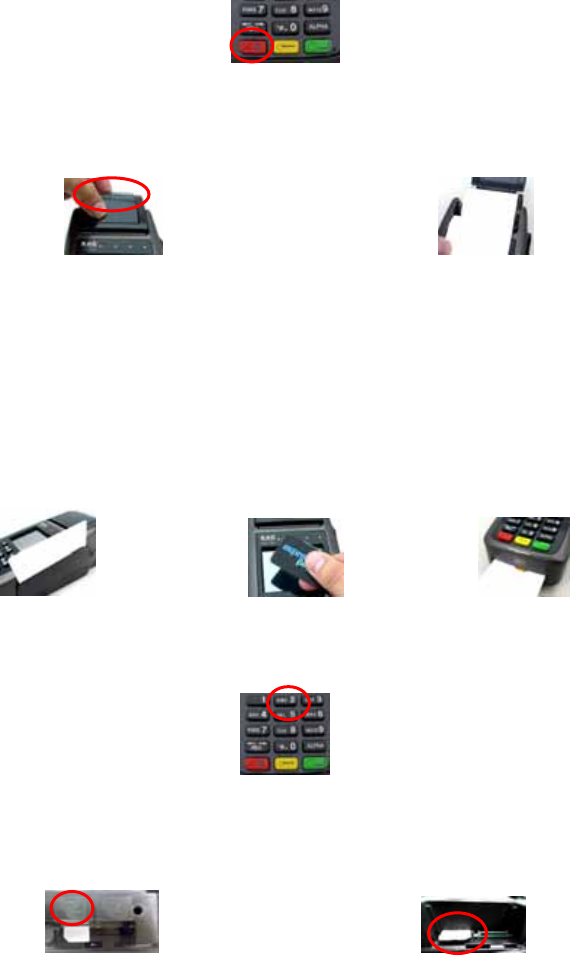
surge suppressor (recommended) after the power cord is connected to the power adapter. Press the “Cancel”
button at the front of device (Figure 10) until the system is booted up.
Figure 10
3. LOADING THE PAPER
Gently pop the printer cover’s latch to open the cover (Figure 11); then lift the cover. Load a roll of thermal
paper (Appleton 1012 recommended) into the printer (Figure 12). Load it so that the print-side of the paper will
feed out facing the operator. Close the cover by pressing down evenly on both side tabs, or by pressing on the
center of the printer cover. Use the serrated bar to tear off any excess paper.
Figure 11 Figure 12
4. USING THE MAGNETIC CARD READER
Magnetic Card Reader
Find the card reader slot at the right side of terminal. Slide the card in either direction through the slot without
stopping. If the card swipe fails, check the position of the magnetic stripe and slide the card again (Figure 13).
Contactless Card Reader
Contactless reader antenna is around the display and PIN pad. It will light up with blue color signal when
terminal is powered on and that means reader is working normally. Put contactless card to approach the
antenna of card reader (Figure 14) for reading the card data during transaction.
Smart Card Reader
The Integrated Circuit Card (ICC) reader is located at the most bottom end (Figure 15). Please make sure that
ICC side is facing upward when inserting into the slot.
Figure 13 Figure 14 Figure 15
5. USING THE KEY PAD
To enter numbers or letters, simply press the appropriate key. For example, to type the letter B: Press and
release [B] twice times, then display shows B (Figure 16).
Figure 16
6. INSTALLING THE SAM CARD
There are four SAM slots located on the left side of the device (Figure 17). Before insert the SAM card, please
turn off the device. Insert the SAM card in the slot in figure 17. Make sure SAM cards inserted in the right
direction (Figure 18).
Figure 17 Figure 18
7. INSTALLING THE PRIVACY SHIELD
The privacy shield of the T103 shows as figure 19. We need to tear the tap around the privacy shield (Figure 20),
and please stick the privacy shield on around the 15-key keypad (Figure 21).
The terminal is compliant with PCI privacy screen design requirement when the detachable privacy shield is
installed on the device. Any change to or removal of this privacy shield will cause security concerns.
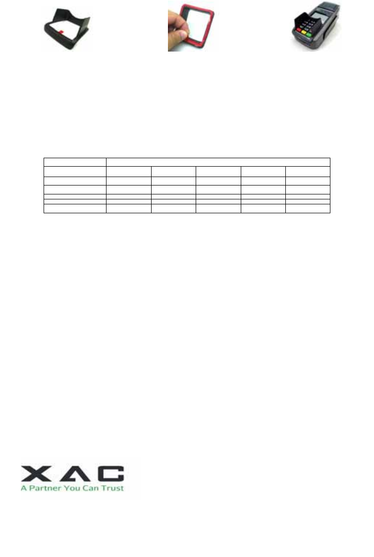
Figure 19 Figure 20 Figure 21
Caution: When removing bottom cover for the purposes of cable or SAM card installation, remember to reinstallation the protective cover and make sure to keep it in place.
Caution: To reduce the risk of fire, use only No. 26 AWG or larger UL Listed or CSA Certified Telecommunication Line Cord.
Caution: Risk of explosion if the battery is replaced by an incorrect type. Please dispose of used battery according to the instructions.
Warning: This is a Class A product. In a domestic environment this product may cause radio interference in which case the user may be required to take adequate measures.
Warning: If the device, T103, is used without the detachable privacy shield, the following criteria needs to be met by the Installed Environment of the PED for complying with the PCI privacy screen design requirement:
A. Positioning of the PED on the check-stand in such way as to make visual observation of the PIN-entry process infeasible.
Visual shields designed into the check-stand.
Position the PED so that it is angled in such a way to make PIN spying difficult.
B. Pop-up (temporary) privacy shield attached to the PED mounting stand. Consumer (through education & prompting) or merchant would put the shield in place during PIN entry.
C. Installing PED on an adjustable stand that allows consumers to swivel the terminal sideways and/or tilt it forwards/backwards to a position that makes visual observation of the PIN-entry process difficult.
D. Positioning of in-store security cameras such that the PIN-entry keypad is not visible.
E. Instructing the cardholder regarding safe PIN-entry, done with a combination of:
Signage on the PED.
Prompts on the display, possibly with a "click-through" screen.
Potentially literature at the point of sale.
A logo for safe PIN-entry process.
Table A1: Matrix of Observation Corridors and PIN Protection Method
Observation Corridors
Method Cashier Customers
in Queue Customers
Elsewhere On-Site
Cameras Remote
Cameras
PED Stand A M H L L L
PED Stand B H H H L M
Check-Stand A L M M L H
Check-Stand B H H M H H
Customer Instructio
n
H* H* H* H* H*
z Customer Instruction methods are less repeatable and therefore should be used in combination with other methods. L = low, M = medium, H = high.
Caution: This equipment should be installed and operated with minimum distance 20cm between the radiator & your body. This transmitter must not be co-located or operating in conjunction with any other antenna or transmitter.
Caution: Use only shielded signal cables to connect I/O devices to this equipment. You are cautioned that changes or modifications not expressly approved by the party responsible for compliance could void your authority to operate the
equipment.
This device complies with Part 15 of the FCC Rules. Operation is subject to the following two conditions: (1) This device may not cause harmful interference, and (2) this device must accept any interference received, including
interference that may cause undesired operation.
Federal Communication Commission Interference Statement
This equipment has been tested and found to comply with the limits for a Class A digital device, pursuant to part 15 of the FCC Rules. These limits are designed to pro-vide reasonable protection against harmful interference when the
equipment is operate din a commercial environment. This equipment generates, uses, and can radiate radiofrequency energy and, if not installed and used in accordance with the instruction manual, may cause harmful interference to
radio communications. Operation of this equipment in a residential area is likely to cause harmful interference in which case the user will be required to correct the interference at his own expense.
FCC Caution: Any changes or modifications not expressly approved by the party responsible for compliance could void the user's authority to operate this equipment.
IMPORTANT NOTE:
FOR DEVICE USAGE
Radiation Exposure Statement:
The product comply with the FCC RF exposure limit set forth for an uncontrolled environment and are safe for intended operation as described in this manual. The further RF exposure reduction can be achieved if the product can be
kept as far as possible from the user body or set the device to lower output power if such function is available.
This transmitter must not be co-located or operating in conjunction with any other antenna or transmitter.
Warning: This is a Class A product. In a domestic environment this product may cause radio interference in which case the user may be required to take adequate measures.
FCC REQUIREMENTS
This equipment complies with Part 68 of the FCC rules and the requirements adopted by the ACTA. On the bottom of this equipment is a label that contains, among other information, a product identifier in the format US:
N7KMM01BT103WIFI3.
If requested, this number must be provided to the telephone company.
Applicable connector jack Universal Service Order Codes (“USOC”) for the Equipment is RJ11C.
A plug and jack used to connect this equipment to the premises wiring and telephone network must comply with the applicable FCC Part 68 rules and requirements adopted by the ACTA. A compliant telephone cord and modular plug is
provided with this product. It is designed to be connected to a compatible modular jack that is also compliant. See installation instructions for details.
The REN is used to determine the number of devices that may be connected to a telephone line. Excessive RENs on a telephone line may result in the devices not ringing in response to an incoming call. In most but not all areas, the
sum of RENs should not exceed five (5.0). To be certain of the number of devices that may be connected to a line, as determined by the total RENs, contact the local telephone company. For products approved after July 23, 2001, the
REN for this product is part of the product identifier that has the format US: N7KMM01BT103WIFI3. The digits represented by 01B are the REN without a decimal point (e.g., 03 is a REN of 0.3).
If this terminal causes harm to the telephone network, the telephone company will notify you in advance that temporary discontinuance of service may be required. But if advance notice isn't practical, the telephone company will notify the
customer as soon as possible. Also, you will be advised of your right to file a complaint with the FCC if you believe it is necessary.
The telephone company may make changes in its facilities, equipment, operations or procedures that could affect the operation of the equipment. If this happens the telephone company will provide advance notice in order for you to
make necessary modifications to maintain uninterrupted service.
If trouble is experienced with this terminal, for repair or warranty information, please contact
COMPANY: Zakus, INC.
ADDRESS: 146 Main Street, suite 208 Los Altos, CA 94022 U.S.A
TEL NO: 650-917-9158
The above information is the exclusive intellectual property of XAC Automation Corporation and shall not be disclosed,
distributed or reproduced without permission of XAC Automation Corporation.
XAC AUTOMATION CORP. shall not be held liable for technical and editorial omissions or errors made herein; nor for
incidental or consequential damages resulting from the furnishing, performance or use of his material.
XAC Automation Corporation
886-3-577-2738