XAC Automation XAPT103PU Terminal User Manual
XAC Automation Corporation Terminal
UserManual.wiki
>
XAC Automation
>
XAPT103PU User Manual
User Manual.pdf
Navigation menu
Upload a User Manual
Namespaces
Wiki Guide
HTML
PDF
Info
Views
User Manual
Discussion / Help
Navigation

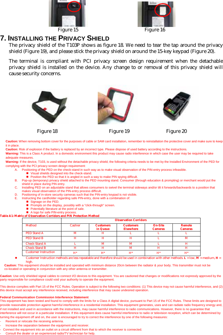
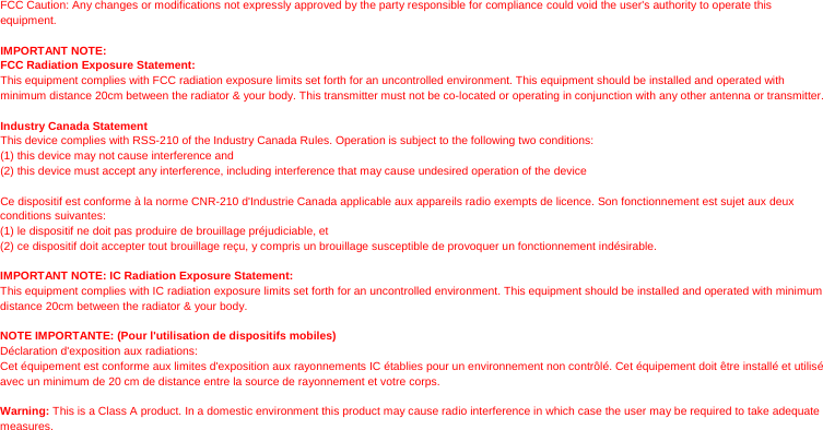
![Figure 8 3. LOADING THE PAPER Gently pop the printer cover’s latch to open the cover (Figure 9); then lift the cover. Load a roll of thermal paper (Appleton 1012 recommended) into the printer (Figure 10). Load it so that the print-side of the paper will feed out facing the operator. Close the cover by pressing down evenly on both side tabs, or by pressing on the center of the printer cover. Use the serrated bar to tear off any excess paper. Figure 9 Figure 10 4. USING THE CARD READER Magnetic Card Reader Find the card reader slot at the right side of terminal. Slide the card in either direction through the slot without stopping. If the card swipe fails, check the position of the magnetic stripe and slide the card again (Figure 11). Contactless Card Reader Contactless reader antenna is around the display and PIN pad. It will light up with blue color signal when terminal is powered on and that means reader is working normally. Put contactless card to approach the antenna of card reader (Figure 12) for reading the card data during transaction. Smart Card Reader The Integrated Circuit Card (ICC) reader is located at the most bottom end (Figure 13). Please make sure that ICC side is facing upward when inserting into the slot. Figure 11 Figure 12 Figure 13 5. USING THE KEY PAD To enter numbers or letters, simply press the appropriate key. For example, to type the letter B: Press and release [B] twice times, and then the screen displays “B” (Figure 14). Figure 14 6. INSTALLING THE SAM CARD Open the battery compartment cover behind the device (Figure 15), and find the SAM card slot on the right side of the terminal (Figure 16). Before insert the SAM card, please turn off the device. Insert the SAM card in the slot as figure. Make sure the SAM card is inserted in the right direction (Figure ).](https://usermanual.wiki/XAC-Automation/XAPT103PU/User-Guide-2108815-Page-3.png)